
Network architecture
Network architecture
-
The following diagram shows the network architecture of this solution:
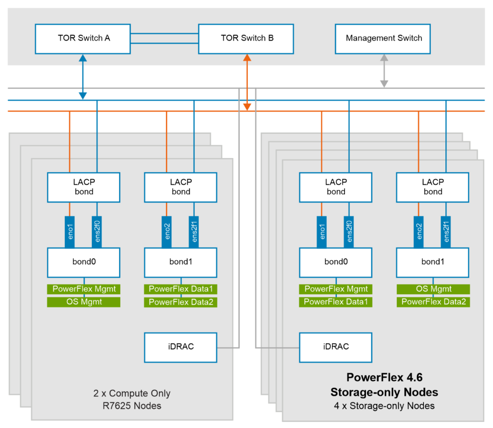
Figure 6. Network architecture
The following table describes the nodes in the network architecture:
Table 2. Node details table
Node
Description
PowerFlex compute-only node: bond0
This bond interface is for OS management, and PowerFlex management.
PowerFlex compute-only node: bond1
This bond interface is for the PowerFlex data network.
PowerFlex storage-only node: bond0
This bond interface is for PowerFlex storage management and data network.
PowerFlex storage-only node: bond1
This bond interface is for the PowerFlex data network.
At the physical layer, two supported Top of Rack (TOR) switches are used for redundancy and load-balancing purposes. A peer link is configured on both the TOR switches. VLANs are created to separate different traffic types on the network bonds.
The following table shows the different networks that are configured for this solution.
Table 3. Network details
Network type
VLAN ID
Operating System (OS) Management
105
PowerFlex Management
150
PowerFlex Data 1
152
PowerFlex Data 2
153