
Testing Advanced NPAR on Dell PowerEdge MX with Broadcom 57504 NICs
Testing Advanced NPAR on Dell PowerEdge MX with Broadcom 57504 NICs
-
The configuration process for Advanced NPAR on the Dell PowerEdge MX requires three broad steps:
- Phase 1: Enable Advanced NPAR in device settings, and verify that it is enabled.
- Phase 2: Create an uplink to add the fabric.
- Phase 3: Create a template from the server with Advanced NPAR enabled, and modify it to assign VLANs.
Phase 1: Enabling Advanced NPAR in device settings
First, log into the OME Modular console. Navigate to the server whose profile you want to use as a template. Launch the Virtual Console and boot into Lifecycle Controller, rebooting the server before continuing.
To configure a NIC port for NPAR in Lifecycle Controller, navigate to Device Settings. Select the NIC Port you want to configure (we chose Port 1), and select Device Level Configuration. To use the Advanced NPAR features, select Advanced NPAR from the Virtualization Mode drop-down and enable NPAREP Mode, which allows virtualization of four ports. (See Figure 2.)
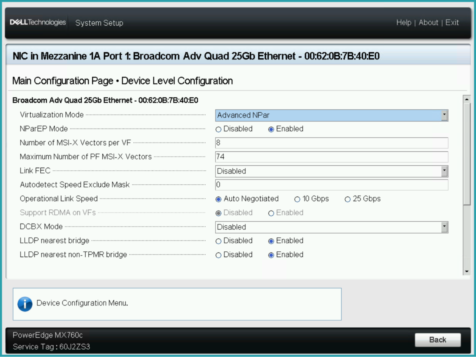
Figure 2. Enabling Advanced NPAR in the Lifecycle Controller console
After completing the process, continue configuring NIC Partitioning. Ensure that NIC+RDMA is set to Disabled before following the on-screen prompts to finish configuration and exit the console. (See Figure 3).
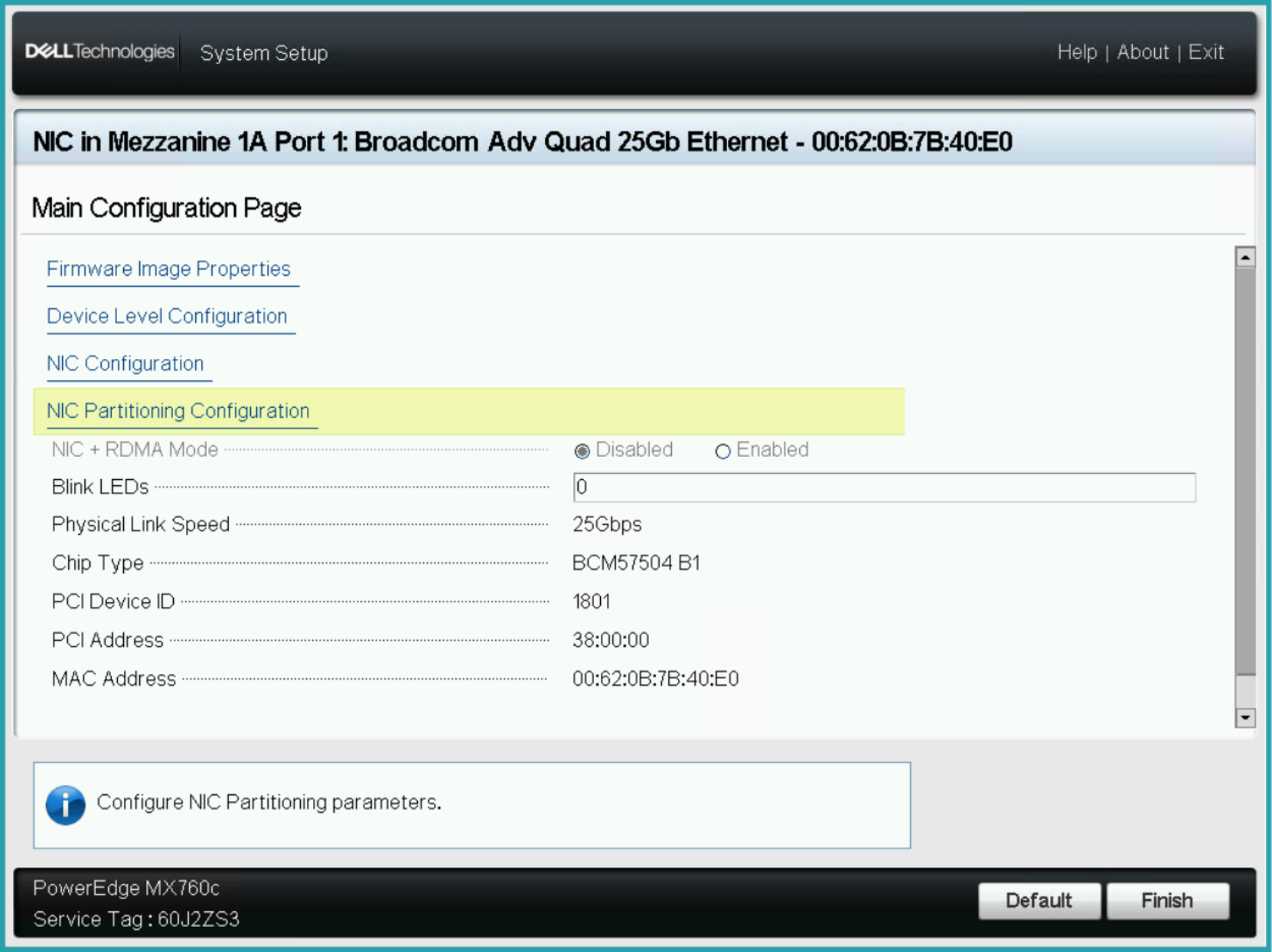
Figure 3. Configuring NIC Partitioning parameters in the Lifecycle Controller console
You can verify that you have correctly enabled Advanced NPAR in multiple ways:
- In device settings, ensure that Advanced NPAR is configurable and editable for some basic settings.
- In iDRAC, each port is now split into several different partitions where they were not before the settings changed.
- ESXi shows an increase in the number of available Network Adapters.
- The OME-M device Port Information page that shows the added partitions for the Ethernet ports.
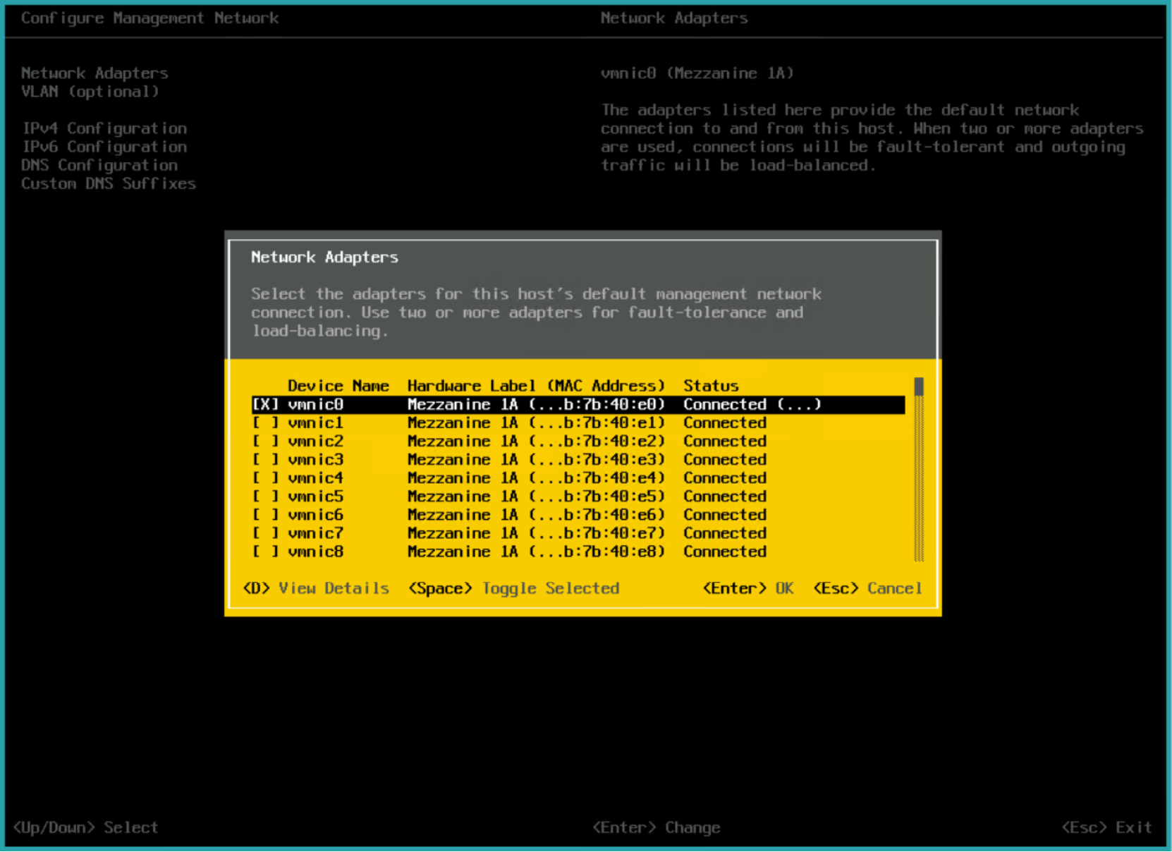
Figure 4. Looking at the number of network adapters available in ESXi to confirm that Advanced NPAR is enabled
Phase 2: Creating an uplink to add the fabric
Once Advanced NPAR is enabled, you must ensure that the MX fabric is properly configured and has an uplink. From the OME-M console, navigate to the fabric that you want to configure and add an uplink, giving it an appropriate name and description. For our test purposes, we selected Ethernet - No Spanning Tree as the uplink type. (See Figure 5.)
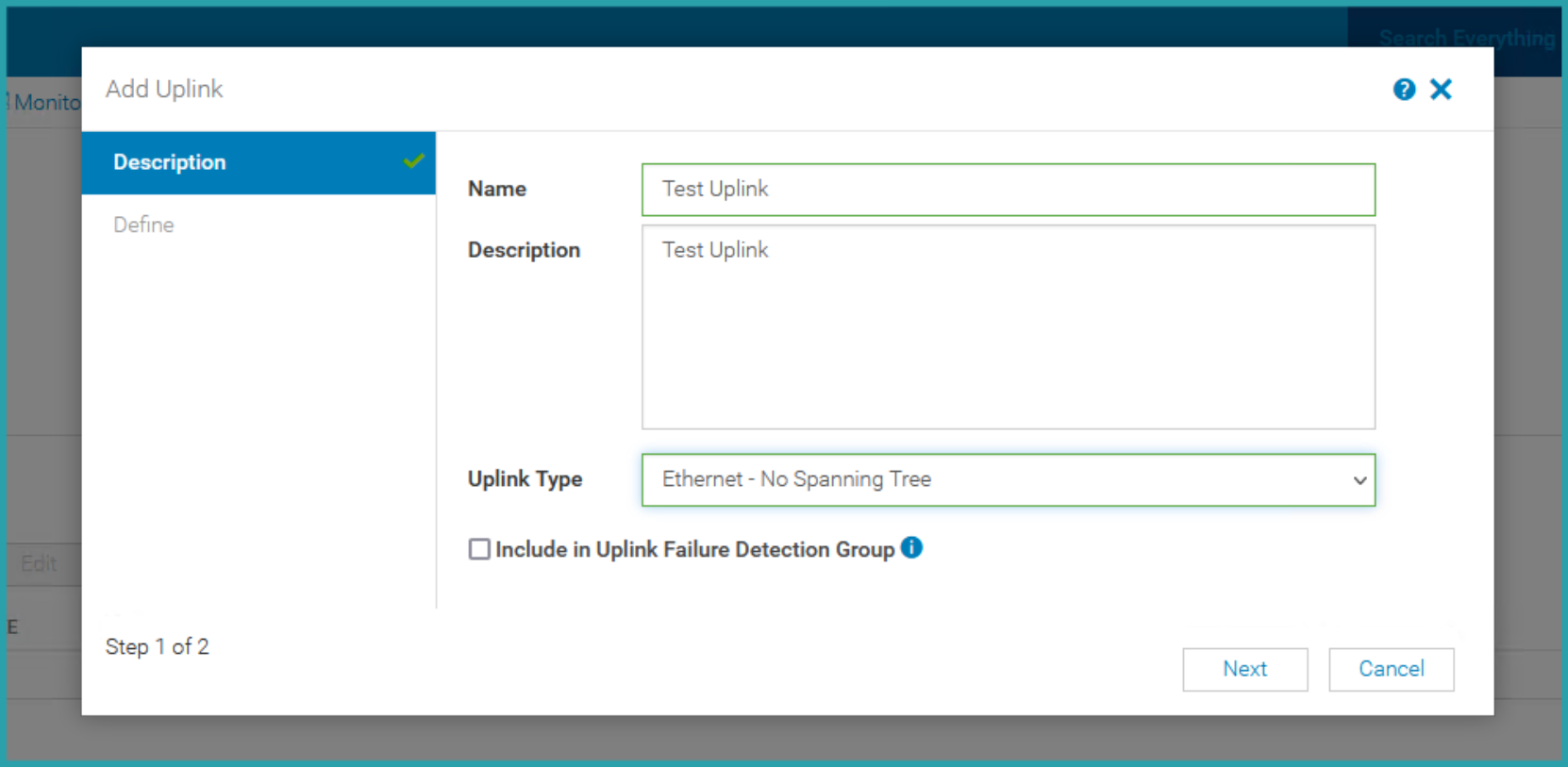
Figure 5. Adding a fabric uplink in OME-M
Select the switch for which you want to create an uplink as well as the appropriate switch ports. In our tests, we selected the VLANs for use in Advanced NPAR, leaving VLAN 1 untagged (see Figure 6).
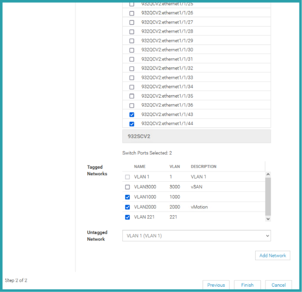
Figure 6. Tagging the appropriate switches and ports for the fabric uplink
Phase 3: Creating a server profile template
To assign VLANs to the created ports, navigate to Templates, and create a new template. (Note: We used a template from a reference server previously configured with advanced NPAR.) Edit the template and assign VLANs to match the configuration you desire (see Figure 7).
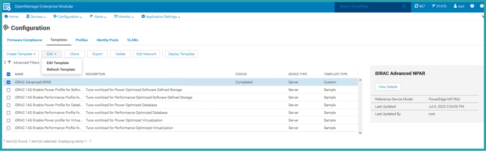
Figure 7. Editing a template in OME-M
From the Edit Components tab (see Figure 8), click Networking to select the ports, and label VLANs as tagged or untagged as appropriate (see Figure 9).
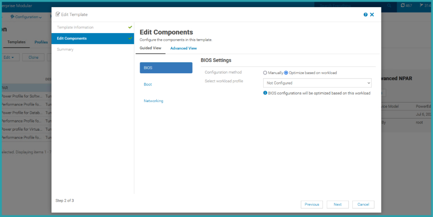
Figure 8. The Edit Components screen in the Edit Template menu
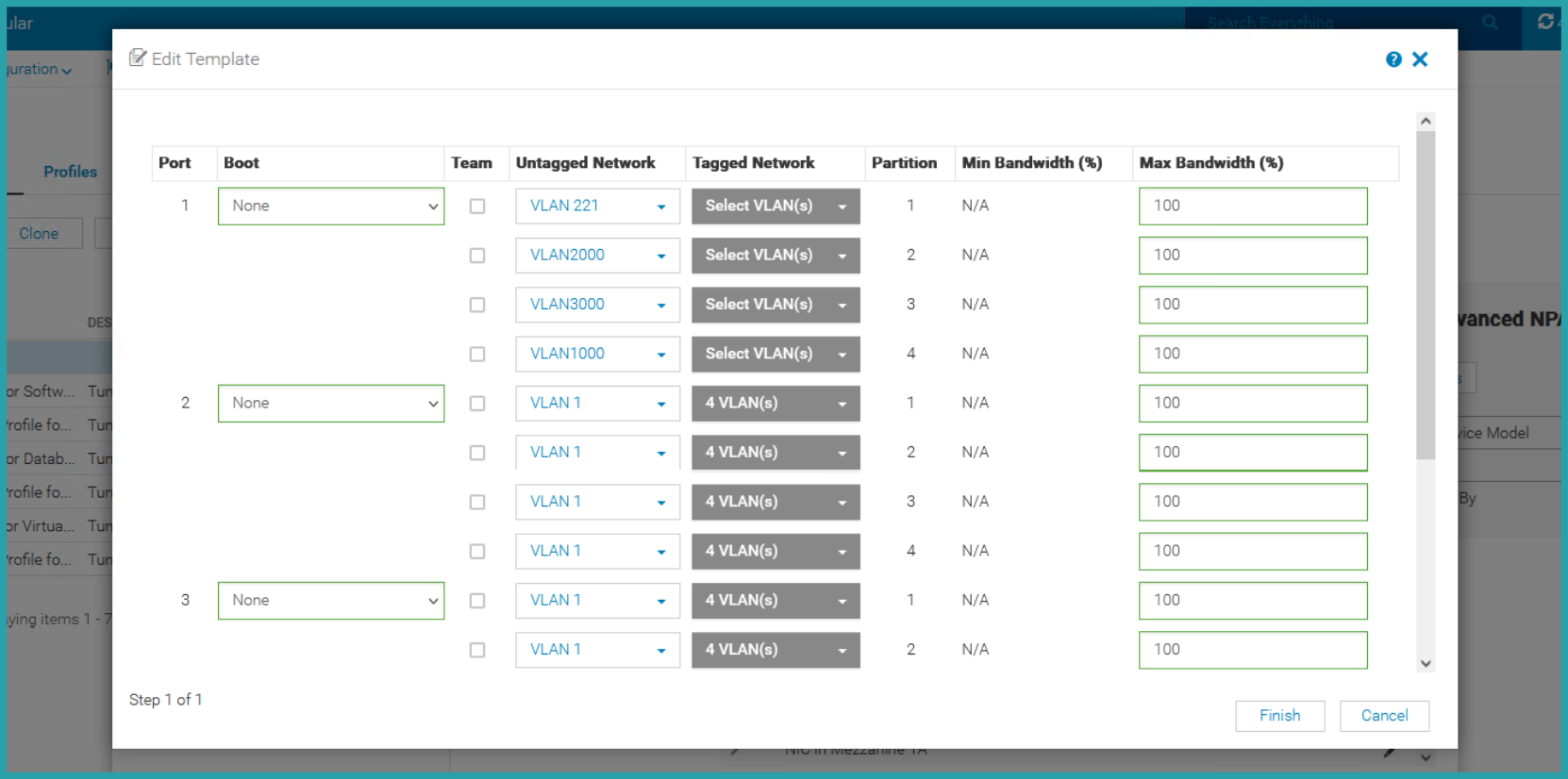
Figure 9. Assigning VLANs as tagged or untagged in the Edit Template menu
Now that the template is created, you can assign it to other PowerEdge servers by choosing Deploy Template on the Template screen. Here, you can select Deploy to Devices [Select Sleds] to choose the server sleds you want to deploy the template to (see Figure 10).
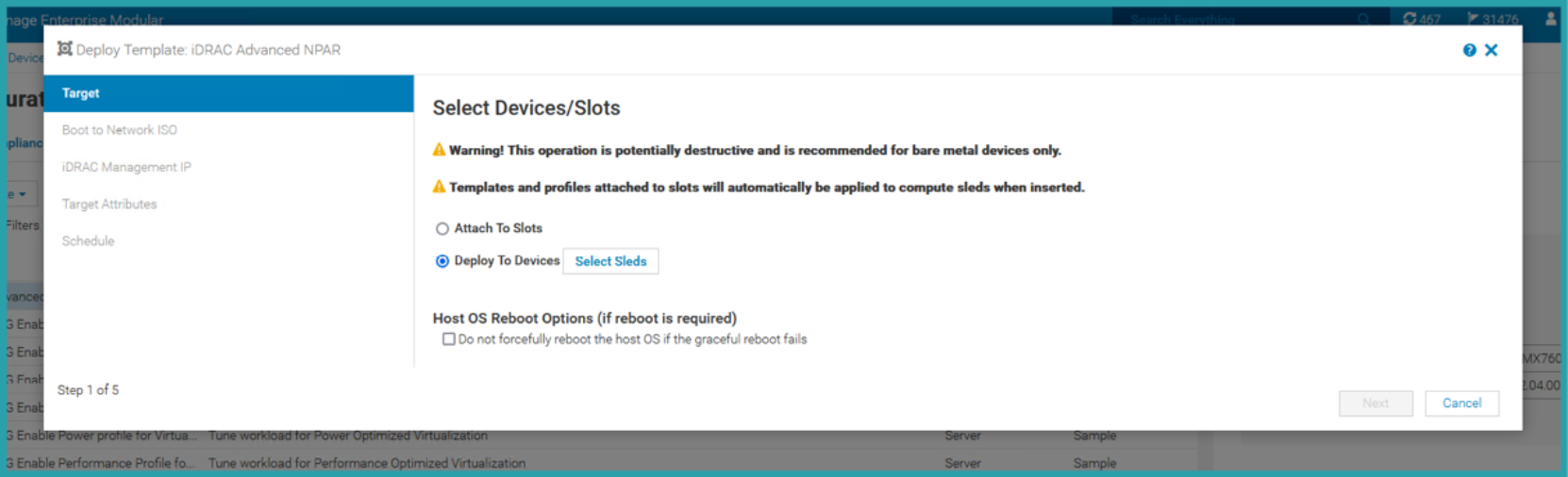
Figure 10. Selecting the server sleds to deploy a template to
For our test purposes, we selected all the server sleds that had we enabled for Advanced NPAR, and deployed the created template to them (Figure 11).
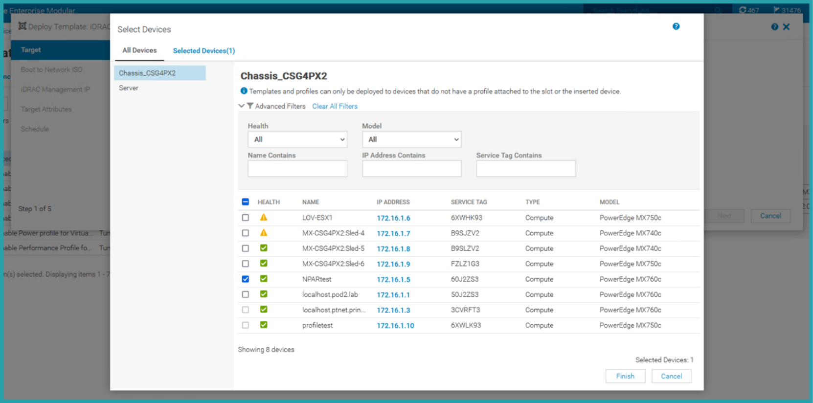
Figure 11. Selecting servers for template deployment