
Before we begin the configuration, we must plan the networking configuration.
This implementation connects MC nodes to PowerFlex nodes over two IP networks. These networks are referred to as SDS networks (SDS-1 and SDS-2) throughout this implementation guide.
The following diagram shows a typical customer environment, where one pair of ToR switches is configured for the APEX Cloud Platform for Azure cluster and another pair is configured for the PowerFlex cluster. These two pairs of ToR switches are connected to a common pair of aggregation switches. As part of this Dell Validated Design, Dell also supports a single pair of ToR switches, shared by both clusters.
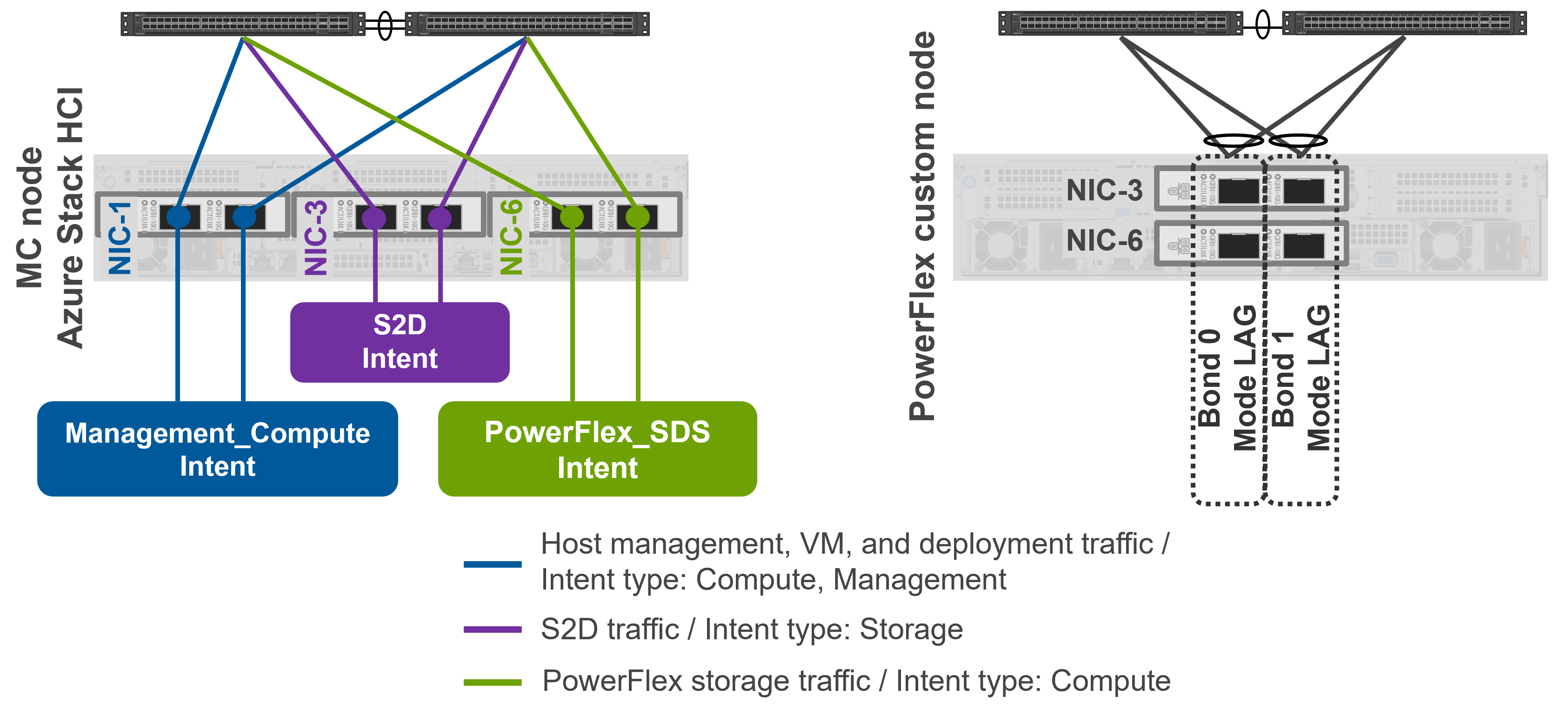
Each MC node will be shipped with a dedicated dual-port NIC (NIC 6 in the diagram above) for use exclusively for the SDS networks. One 25 Gbps switch port will be connected per ToR switch, local to the cluster. This translates to two 25 Gbps ports used on each MC node, connected to separate ToR switches specifically for the SDS networks.
For the PowerFlex nodes, two 25 Gbps switch ports per ToR, per node are used for the SDS networks. One port from each physical NIC is connected to a separate ToR switch. There are no specific physical networking requirements for this deployment for the PowerFlex cluster. The SDS networks for this Dell Validated Design are already configured on the PowerFlex nodes and corresponding ToR switches.