
A port channel, also known as a LAG, or link aggregation, increases bandwidth and provides failover redundancy between two switches. The port channel is created using two or more cables between the devices. Use two cables to double bandwidth, three cables to triple bandwidth, or four cables to quadruple bandwidth. Like ports with the same speed are a best practice when combining to form the port channel.
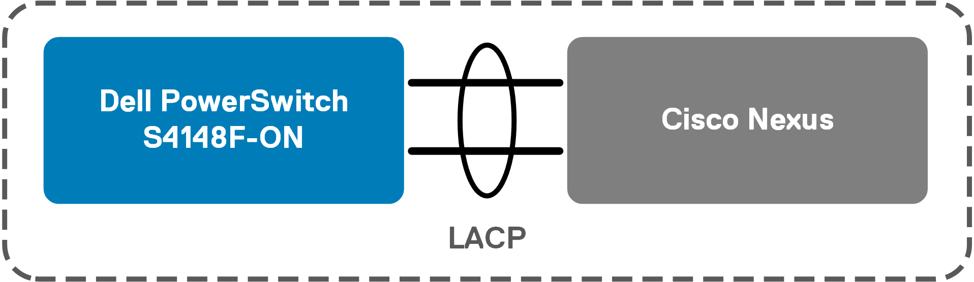
Two cables are used in this example which doubles the bandwidth supplied by a single cable. In the commands below, ports 1/1/15 and 1/1/16 from the Dell switch and ports 1/17 and 1/18 from a Cisco Nexus are used to form a port channel. The interface port-channel command is run from the global configuration mode to create the group. The channel-group command is then run from the interface configuration mode to assign ports to the group. The preferred mode active option is used to create an LACP port channel which allows negotiations with other ports to automate LAG connections. SmartFabric OS10 supports up to 128 port channels with up to 32 ports (per switch) per channel. In this example, port channel 1 is created and assigned two ports per switch.
| Configure a port channel on the Dell switch | Configure a port channel on the Cisco Nexus |
| |
The show port-channel summary command may be used on each switch to validate the port channel and its member ports are up. The show lldp neighbors command may be used on each switch to verify which ports are connected between switches.
Validate port channels for each switch
OS10# show port-channel summary

Flags:  D – Down    I – member up but inactive    P – member up and active
        U – Up (port-channel)
Group Port-Channel          Type     Protocol  Member Ports
1    port-channel1    (U)    Eth      DYNAMIC   1/1/15(P) 1/1/16(P)

switch# show port-channel summary
Flags:  D – Down        P – Up in port-channel (members)
        I – Individual  H – Hot-standby (LACP only)
        s – Suspended   r – Module-removed
        S – Switched    R – Routed
        U – Up (port-channel)
        M – Not in use. Min-links not met
Group Port-       Type     Protocol  Member Ports
      Channel
1     Po1(SU)     Eth      LACP      Eth1/17(P)   Eth1/18(P)
Verify port connections between switches
OS10# show lldp neighbors
Loc PortID          Rem Host Name        Rem Port Id                    Rem Chassis Id
ethernet1/1/15      switch                Eth1/17                       00:2a:6a:f7:80:58
ethernet1/1/16      switch                Eth1/18                       00:2a:6a:f7:80:59

switch# show lldp neighbors
Capability codes:
  I Router, (B) Bridge, (T) Telephone, (C) DOCSIS Cable Device
  (W) WLAN Access Point, (P) Repeater, (S) Station, (O) Other
Device ID            Local Intf      Hold-time  Capability  Port ID
OS10                 Eth1/17         120        PBR         ethernet1/1/15
OS10                 Eth1/18         120        PBR         ethernet1/1/16
Total entries displayed: 2
VLAN 1 is the default vlan for all Ethernet ports on the switch, and all ports are assigned to this VLAN by default. Other VLANs must be created by the administrator, who can then assign ports to the new VLANs.
The VLANs section demonstrates how to create a VLAN and assign interfaces and port channels to the new VLAN.