
Along with functionality, an important consideration when developing substation software solutions is how quick and simple it is to customize the application for each substation. ABB ZEE600 is based on the zenon SCADA software and contains the features that accelerate development found in the base software, as well as a variety of features specific to the energy industry.
These include:
- ZEE600 project templates
- Automatic line coloring
- IEC and ANSI standard symbols
- ZEE600 device import wizard
- Object import and export
- Driver simulation
ZEE600 project template
The ZEE600 New Project wizard dramatically reduces the time to create a substation project from scratch and ensures a consistent structure throughout all projects.
The general structure of this HMI is to have four sections: single line diagrams, system diagnostics, plant automation, and reporting. Each of these sections can then have up to 12 pages, depending on the size and complexity of the substation. There are also various pop-up screens that are automatically created to enable switching users, viewing and responding to alarms, real-time configuration of the HMI, and various other functions.
Navigation of the HMI is also handled in the project template, through an always-present navigation bar at the top of the screen and an interactive information bar at the bottom. The previously mentioned pop-ups are all accessible, either directly by using the icons on these bars, such as the alarm icon in the top right, or by opening the main menu through the menu icon in the top right and then selecting the desired item.
During the template setup process, there is an option to enter contact details and a customer logo. This logo is displayed at the bottom of the HMI, and the contact details show up in the Utilities pop-up from the main menu. This is a great opportunity for integrators to add their brand to the HMI and show availability for support and development needs.
Automatic line coloring
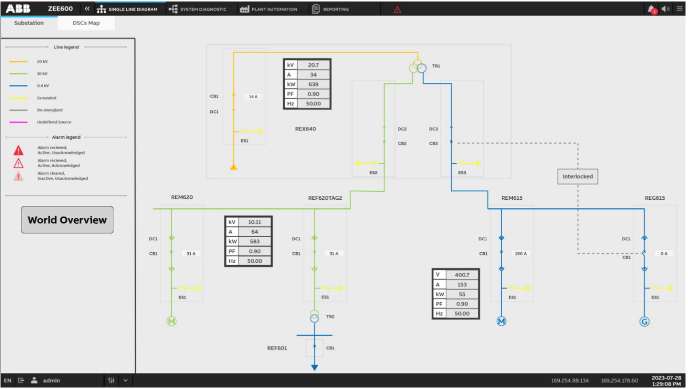
The central page of a substation HMI is the single line diagram. This is where an operator can immediately see which lines are live and how all the different substation components relate to one another. ZEE600 includes a feature called automatic line coloring to speed up the development of this crucial component.
The way this works is that all the basic single line diagram symbols are assigned a role, such as Source, Transformer, and so on, and any line attached to that component inherits the appropriate color. This includes the correct voltage color when active, as defined by either IEEE or ANSI standards, and it changes dynamically depending on the status of the connected components. This allows for very complicated single line diagrams to be created without the need to configure every line.
Standardized IEC and ANSI substation symbols
Most substations are required to follow either IEC or ANSI standards, depending on the country. This includes a specific set of symbols to represent different components in the single line diagram. ZEE600 makes developing these single line diagrams easier by including all the necessary symbols pre-configured so that they can be easily added to the single line diagrams.
Since the same ZEE600 symbols are designed to be used regardless of standard, they can even be switched dynamically. Therefore, as long as standard icons are used, the same project can be deployed in substations that use IEEE and ANSI without any change.
ZEE600 object import wizard
A major stage of developing substation automation is to connect specific devices through an IED and create appropriate graphics. ZEE600 makes this task much easier by including an object import wizard.
The first step in this wizard is to define the substation structure by identifying the substation name, voltage level, and bay ID. Use this information when naming components to simplify filtering. This bay structure is then stored in the Equipment Modeling section and can be used to assign authorization or aggregate alarms according to the defined hierarchy.
Once the bay structure is complete, components are then individually added to each bay. The pre-configured ones include circuit breakers, transformers with tap changers, metering devices, and ABB SWICOM devices. After selecting the category of device, the specific symbol can be chosen and assigned to a specific single line diagram (where multiples exist). If no preconfigured symbol exists, a generic object can be created and later connected to objects on the screen.
At the time of writing, the only objects that can be imported through the wizard are those that use either Modbus or IEC 61850 communication. For other devices, such as DNP3, it is still possible to take advantage of the wizard by creating a temporary Modbus device, and later updating the communication configuration.
Object import and export
Virtually all objects (tags, pages, functions, and so on) can be exported to an XML file format using the Export selected as xml option found by right-clicking on the object in the project manager. This is useful for scaling up development as you can export the xml, use a text editor to replace key values (such as communication addresses), and then import the xml as a new device. This also allows for easy development of a single project in parallel amongst multiple engineers because each engineer is responsible for their specific component xml file and can set up their project as they choose.
Furthermore, configuring hundreds of tags for various protocol drivers can be a tedious process. ZEE600 allows the export of a single tag or a few tags to a CSV file format, where these template tags can quickly and easily be replicated programmatically or based on a pattern. This extended CSV file can then be imported back into the ZEE600 project to rapidly scale the data ingest configuration.
Simulated drivers
One of the best features for accelerating time to deployment and improving quality is the built-in option to simulate drivers. This enables HMI and automation development and testing without the need for actual hardware. When the hardware becomes available, a simple switch makes it easy to test and use actual hardware communications.
For relatively simple projects, the option to set a driver to Constant or Counting is sufficient. For the Constant setting, all tags are set to their initial value (this typically defaults to 0 for all number types). The values can then be changed through the HMI or through automation programming. If Counting is selected, the tags start at their initial value and increase by one every second for numeric tags or alternate between true and false for binary tags. This is useful for situations where seeing a number change is important, such as with trend lines.
For most projects however, it is worth developing a simulated driver. This allows for realistic variable values, expected variable interactions, and appropriate use of automation and alarms. Setting up these simulated drivers is done by right-clicking on the driver and selecting new / edit simulation. This brings up the programming interface, and code can be written in any of the IEC 61131 languages.