
Uplinks to the existing network may be configured as L2 or L3 uplinks. This section describes how to configure L2 uplinks.
Note: If you use L3 uplinks, go to Configure L3 routed uplinks to external network. If there is no preference for the uplink type, L2 uplink configuration has fewer steps than L3 uplink configuration.
The following figure shows how to cable the switches.
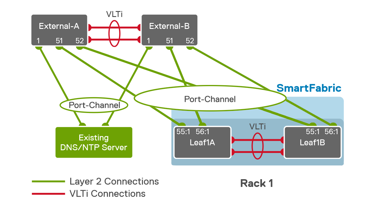
Note: All ports on the four switches shown in the figure are in the External Management VLAN, 1811.
When the L2 uplink configuration is complete, Leaf1A and Leaf1B connect with a VLT port channel to a switch pair External-A and External-B. In this example, an existing DNS/NTP server also connects to the external switches using a VLT port channel. In this guide, all VLT port channels use LACP.
Note: You do not need to use this method to connect the DNS and NTP servers if they are reachable on the network