
PowerMax: Storage Directors Ports and Interface Emulations
PowerMax: Storage Directors Ports and Interface Emulations
-
Two validation tests were combined into one best practice for the PowerMax Storage Directors. The first test involved configuring the PowerMax Director to only use the interfaces used by the business. For the second-best practice, we increased the number of front-end connections to improve bandwidth between the PowerMax storage and PowerEdge servers. We combined these best practices as they both apply to configuring the PowerMax Directors.
Category
PowerMax Storage
Product
PowerMax Front-end Connections
Type of best practice
Performance Optimization
Day and value
Day 1, Highly recommended
Overview of Optimizing Director Interfaces
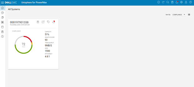
PowerMax storage arrays use bricks that enable customers to add more power, performance, and capacity to an existing array. Each PowerMax brick has two engine directors. These directors support multiple functions, including front-end I/O modules. The front-end I/O modules provide connectivity to the array using various interfaces including Fibre Channel SCSI, Fibre Channel NVMe, iSCSI, and others. In the best practice validation tests, only the Fibre Channel interface was used, which provided the ability to disable unused interfaces like Fibre Channel NVMe and iSCSI.
Unused interfaces on the directors consume processor resources even when running in an idle state. By disabling interfaces, the business does not plan to use the directors can direct more processing power to the interfaces that are being heavily used. The goal is to optimize the director interfaces to support only those used by the business to optimize performance.
This best practice originated from Dell EMC support. It is highly recommended to work with the support team to validate whether this director interface optimization will work for your business.
Overview of Adding Director Front-end I/O Modules
There are four front-end I/O modules per director. In the baseline configuration, two of the four total directors were used. The following table shows all four front-end I/O modules were used on director 2 and two front-end modules were used on director 4. The two other front-end modules on director 4 were reserved for replication. Each front-end module was a 32 Gbps Fibre Channel connection and six total were used in the baseline connection.
Table 1: Front-End Director Port Baseline Configuration
Director number
Port number
Connected
HBA number and port
1
1
2
3
4
2
1
Connected
HBA 1, Port 1
2
Connected
HBA 1, Port 2
3
Connected
HBA 2, Port 3
4
Connected
HBA 2, Port 4
3
1
2
3
4
4
1
Connected
HBA 1, Port 1
2
Connected
HBA 1, Port 2
3
Reserved for replication
4
Reserved for replication
For this best practice two additional directors were added (1 and 3) with all the front-end I/O modules for a total of eight more connections to the server. The following table shows the two directors and eight ports that were added (marked in darker grey):
Table 2: Front-End Director Port Optimized Configuration
Director Number
Port number
Connected
HBA Number and Port
1
1
Connected
HBA 1, Port 1
2
Connected
HBA 1, Port 2
3
Connected
HBA 2, Port 3
4
Connected
HBA 2, Port 4
2
1
Connected
HBA 1, Port 1
2
Connected
HBA 1, Port 2
3
Connected
HBA 2, Port 3
4
Connected
HBA 2, Port 4
3
1
Connected
HBA 1, Port 1
2
Connected
HBA 1, Port 2
3
Connected
HBA 2, Port 3
4
Connected
HBA 2, Port 4
4
1
Connected
HBA 1, Port 1
2
Connected
HBA 1, Port 2
3
Reserved for replication
4
Reserved for replication
With the additional directors and front-end ports, this best practice showed the greatest improvement of all the storage recommendations. Doubling the connections to the database server provided substantial improvements.
Recommendation
The combination of the two PowerMax Director best practices (removing unused interfaces and connecting additional front-end I/O modules) provided a substantial performance boost in the following metrics:
- New Orders per Minute (NOPM)
- Transactions per Minute (TPM)
- Server CPU utilization
- PowerMax IOPS
- PowerMax Average Read Response Time
- PowerMax Average Write Response Time
Both TPC-C metrics (NOPM and TPM) showed a substantial improvement – the number of orders completed and transactions processed increased significantly. Correspondingly, array IOPS also increased significantly. The PowerMax average read and write times dropped significantly, indicating faster responses from storage.
Server CPU utilization went up which is a positive indication of more efficient use of the cores in the server. Until this best practice was implemented processors were likely waiting on read and write I/O from the storage array. Now that the average read and write response times are faster the processors are processing more data thus, are more efficiently used.
Overall, the best practice of adding PowerMax directors and front-end I/O modules and disabling unused interfaces in the director can significantly improve performance. The recommendation is to implement this best practice as a Day 1 activity, as it is a highly recommended configuration that optimizes database performance.
Implementation Steps
In this best practice we removed all the unused iSCSI and NvME emulations and utilized all of the ports of the FE director. In all other cases we tested using two of the FE director ports.
We used FC connectivity from our servers to our storage. For case 6 part 1, we removed additional iSCSI and NvME emulations on the PowerMax. This was useful since our tests were conducted using FC as the backend connectivity between our servers and storage. Unisphere provided the capability to manage the emulations available on the PowerMax storage. These are the necessary steps:
1. To remove unused partitions, log into the Unisphere console with the appropriate credentials.
2. Select the storage section and navigate to the System panel. Navigate to Hardware and click on the Manage Emulation button.
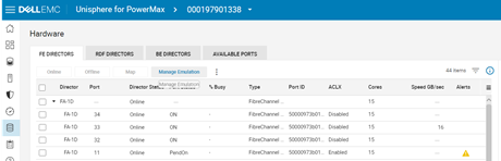
3. Click Remove Director Emulation and then click NEXT. Select the emulation to be removed on the next pane. Review your changes and click FINISH.
If there are no conflicts, the change should proceed. If you encounter any errors, contact PowerMax support.For case 6 part 2, we added one additional port to each director, effectively doubling the number of ports available. To make this change, first create the required FC connections from the storage ports to the switches and zone them appropriately, in other words ensure that the updated zoning maps the new ports to the host (server) ports. Contact Brocade support if there are any issues.
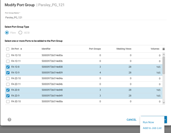
1. Once zoned, navigate to the Hosts pane in Unisphere and select the sub-option for Port Groups.2. Select your port group and click the Modify button. Select the ports to add to the port group, click on the arrow button next to Add to Job List and then click Run Now.
Additional Resources
This best practice was referenced from the Deployment Best Practices for SQL Server Database with Dell EMC PowerMax.