
None
None
-
The following diagram shows the network architecture of this solution.
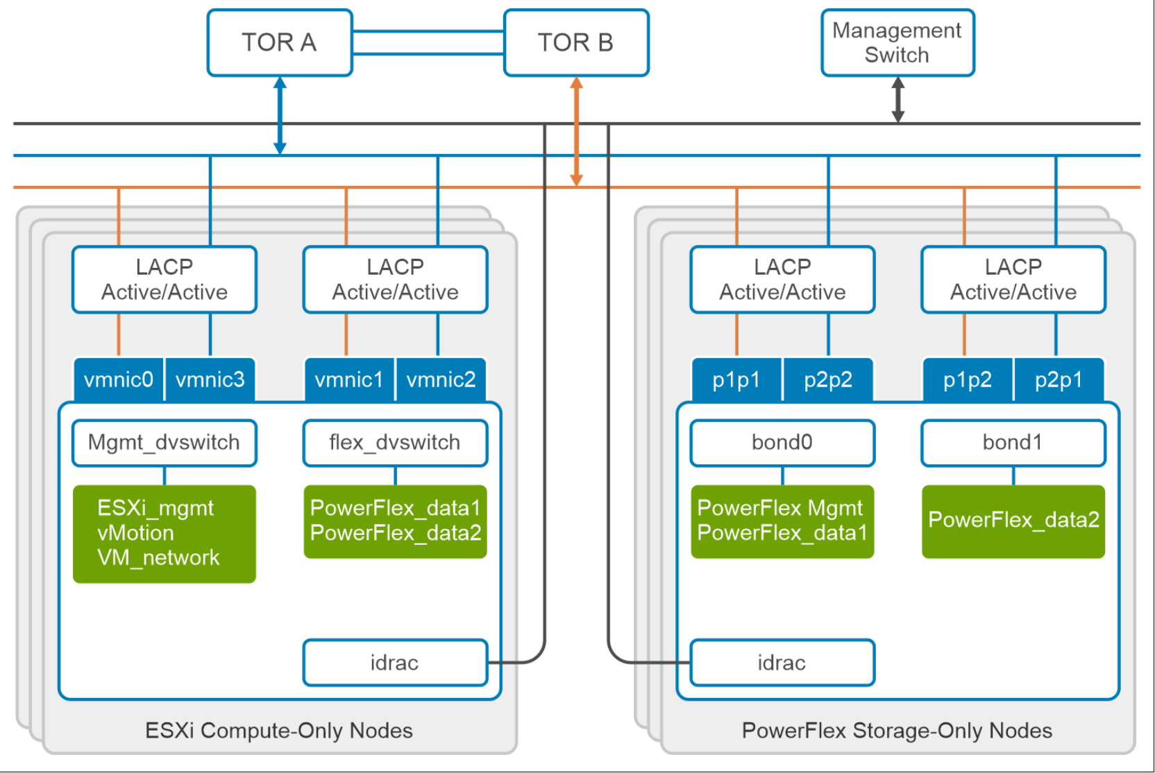
Figure 7. Network architecture
The following table describes the nodes in the architecture:
Table 2. Network description
Node
Description
ESXi compute-only node: Mgmt_dvswitch
This vDS is for ESXi management, vMotion, VM network, application traffic, and so on.
ESXi compute-only node: flex_dvswitch
This vDS is for PowerFlex data network: communication from compute to storage that carries PowerFlex front-end storage traffic.
PowerFlex storage-only node: bond0
This bond interface is for PowerFlex storage management and data network.
PowerFlex storage-only node: bond1
This bond interface is for the PowerFlex data network.
At the physical layer, two supported Top of Rack (TOR) switches are used for redundancy and load-balancing purposes. A peer link is configured on both the TOR switches. VLANs are created to separate different traffic types on the network bonds.
The following table shows the different networks that are configured for this solution.
Table 3. Network details
Network type
VLAN ID
Operating System (OS) Management
105
vMotion
106
PowerFlex Management
150
PowerFlex Data 1
152
PowerFlex Data 2
153
Note: The Operating System Management network must be routable to the PowerFlex Management network to access the PowerFlex cluster.