
None
None
-
The following diagram shows the logical architecture of this solution:
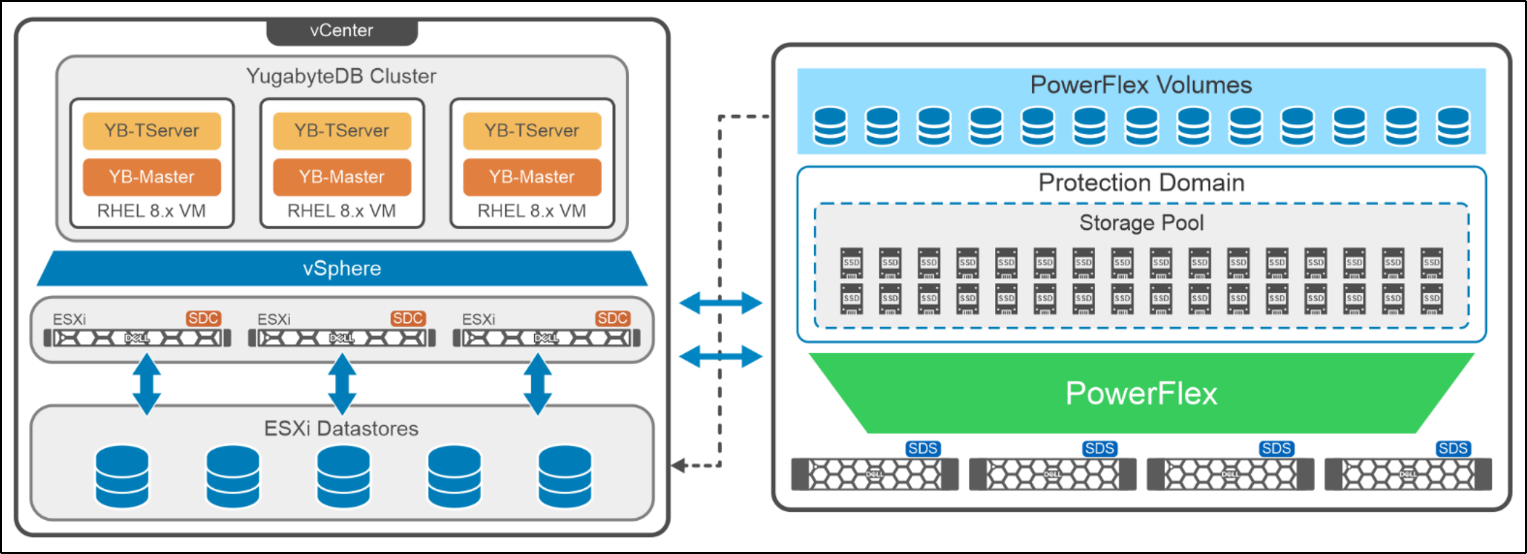
Figure 6. Logical design of YugabyteDB with PowerFlex
PowerFlex Manager is used to deploy a PowerFlex storage-only (SO) cluster on four bare metal servers followed by the deployment of PowerFlex compute-only (CO) nodes. This deployment is fully automated by PowerFlex Manager. For the configuration documented in this paper, the CO nodes are deployed as ESXi servers.
A single PowerFlex protection domain and a single storage pool are configured on PowerFlex. The PowerFlex storage pool topology consists of four SDSs with 10 SSD disks in each of the four SDS nodes. The volumes are created from the storage pool, which is mapped to three compute-only nodes and VMware datastores are created on these volumes (one datastore is created for each ESXi host). These datastores are then used to provision Virtual Machine Disks (VMDKs) for each of the RHEL 8.8 VMs which are used for the YugabyteDB cluster.
YugabyteDB provides a few sample workloads for performance testing, such as a TPC-C, sysbench, YCSB, and others. For more information about these sample workloads, see Benchmark YugabyteDB.
In this paper, the YugabyteDB provided TPC-C workload is used for performance testing and is run from the client machines.
For more information about the configuration of YugabyteDB VMs and the PowerFlex nodes that are used in this solution, see Configuration details.