
None
None
-
The following diagram shows the network architecture that is configured on both the sites.
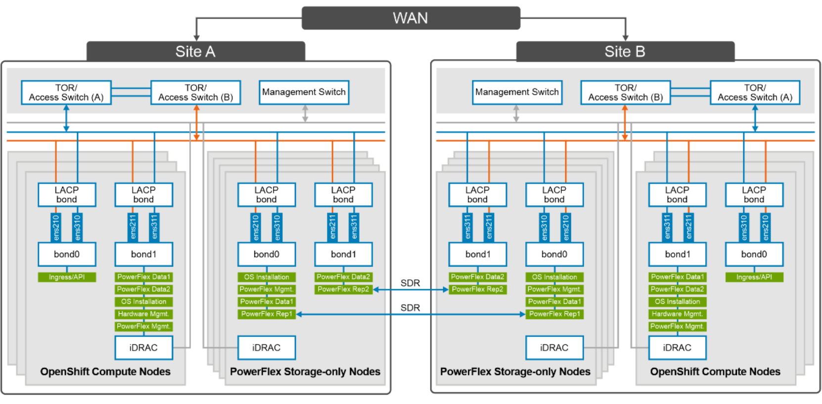
Figure 6. Network design of compute and storage nodes
At the physical layer, two supported Top of Rack (TOR) switches are used for redundancy and load-balancing purpose at each site. A peer link is configured on both the TOR switches.
The network ports of different network interfaces on each PowerFlex node are configured to carry PowerFlex management, PowerFlex data traffic and PowerFlex replication traffic. An LACP bond is configured at the host level with two network interfaces to form a single-bonded (logical) interface for increased bandwidth and redundancy.
The bond0 and bond1 are the LACP bonded interfaces and are configured with multiple VLAN tagged interfaces for all the PowerFlex networks. The traffic is logically separated by creating VLANs which separate different traffic on the bond interfaces as shown in the preceding figure. PowerFlex data1 and data2 are used for data traffic whereas PowerFlex Rep1 and PowerFlex Rep2 are dedicated for replication traffic. The following table shows the different networks that are configured for this solution. See PowerFlex node VLAN setup for more information:
The following table describes the VLAN IDs required for different network types:
Table 2. Network details
Network type
VLAN ID
Ingress/API
105*
Operating System Installation
104
Hardware Management
101
PowerFlex Management
150
PowerFlex Data 1
152
PowerFlex Data 2
153
PowerFlex Rep1
154
PowerFlex Rep2
155
*: 105* is the network required for OpenShift Ingress/API and Internet connectivity is required on this network.
For more information about OpenShift networking, see Configuring and managing cluster networking.
Note: The above network diagram represents the design of one site. Based on physical locations of Site-A and Site-B, it is recommended to enable (TOR-link) connectivity between the two sites for replication.