
None
None
-
The following diagram shows the logical architecture of the PowerFlex replication clusters using two-layer deployment architecture. In this example, on each site there are four nodes that are dedicated for storage. PowerFlex storage (SDS) and replication (SDR) components are installed on these four nodes and three more nodes are dedicated for compute (SDC) on which Red Hat OpenShift cluster is configured. This model decouples compute from storage, allowing either of them to scale independently, as needed.
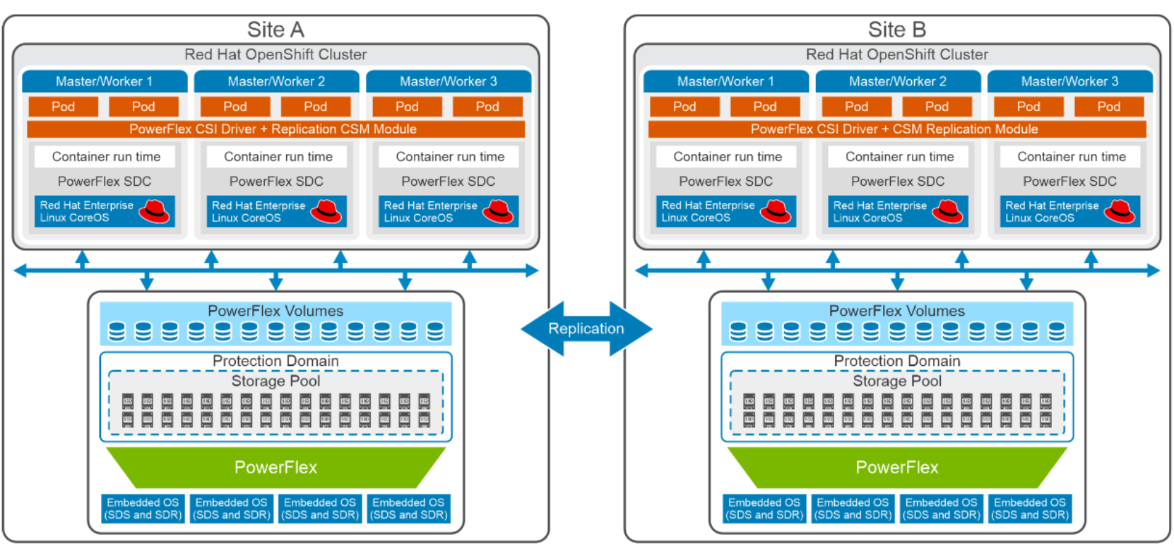
Figure 5. Logical design for PowerFlex replication clusters
Red Hat OpenShift Assisted Installer is used to configure the three bare metal compute-only nodes, creating an OpenShift cluster in each site. These nodes are configured as OpenShift control-plane and worker nodes (also known as a compact cluster).
On the storage side, PowerFlex Manager is used to deploy a PowerFlex Storage Only (SO) cluster on four bare metal servers using templates that help to install the Software defined storage (SDS) and SDS Storage Data Replicator (SDR) components. SDR deployment can be done leveraging the PowerFlex manager UI. Container Storage Modules (CSM) replication sidecar container is installed in each OpenShift cluster, along with the CSI driver to facilitate dynamic provisioning of Persistent volumes and enabling replication for Kubernetes based applications on compute nodes.
For more information about PowerFlex replication technology, see PowerFlex Replication.