
File system structure
File system structure
-
The OneFS file system is based on the UNIX file system (UFS) and, hence, is a very fast distributed file system. Each cluster creates a single namespace and file system. This means that the file system is distributed across all nodes in the cluster and is accessible by clients connecting to any node in the cluster. There is no partitioning, and no need for volume creation. Instead of limiting access to free space and to non-authorized files at the physical volume-level, OneFS provides for the same functionality in software using share and file permissions, and using the SmartQuotas service, which provides directory-level quota management.
Further information is available in the OneFS SmartQuotas white paper.
Because all information is shared among nodes across the internal network, data can be written to or read from any node, thus optimizing performance when multiple users are concurrently reading and writing to the same set of data.
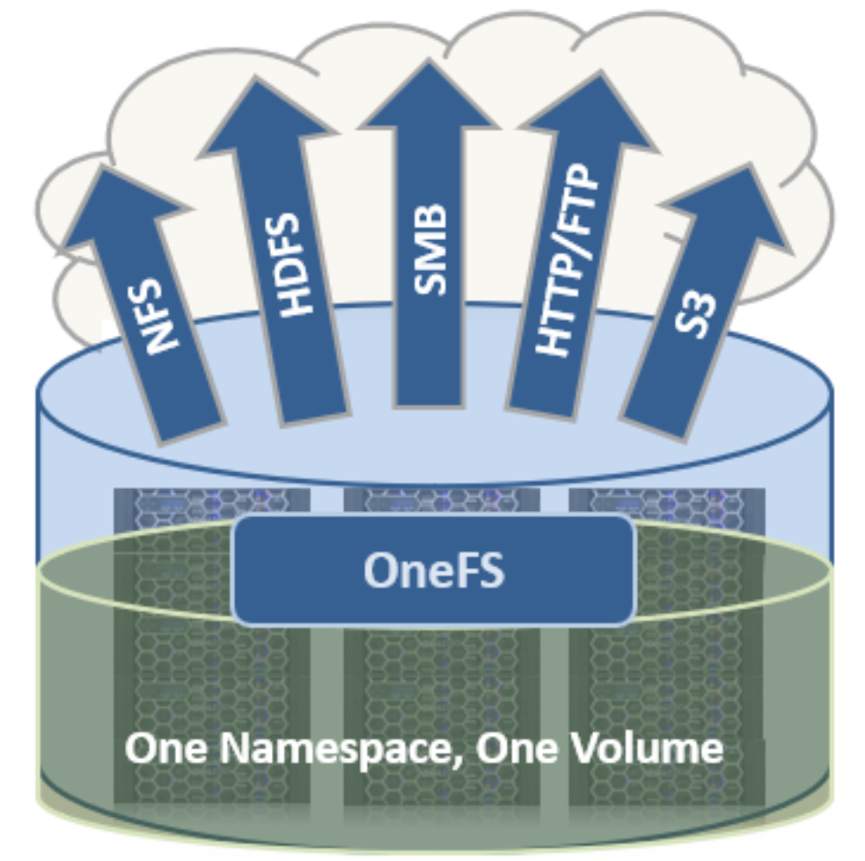
Figure 4. Single file system with multiple access protocols
OneFS is truly a single file system with one namespace. Data and metadata are striped across the nodes for redundancy and availability. The storage has been completely virtualized for the users and administrator. The file tree can grow organically without requiring planning or oversight about how the tree grows or how users use it. No special thought has to be applied by the administrator about tiering files to the appropriate disk, because OneFS SmartPools will handle that automatically without disrupting the single tree. No special consideration needs to be given to how one might replicate such a large tree, because the OneFS SyncIQ service automatically parallelizes the transfer of the file tree to one or more alternate clusters, without regard to the shape or depth of the file tree.
This design should be compared with namespace aggregation, which is a commonly used technology to make traditional NAS “appear” to have a single namespace. With namespace aggregation, files still have to be managed in separate volumes, but a simple “veneer” layer allows for individual directories in volumes to be “glued” to a “top-level” tree using symbolic links. In that model, LUNs and volumes, and volume limits, are still present. Files have to be manually moved from volume-to-volume in order to load-balance. The administrator has to be careful about how the tree is laid out. Tiering is far from seamless and requires significant and continual intervention. Failover requires mirroring files between volumes, driving down efficiency, and ramping up purchase costs, power, and cooling. Overall, the administrator burden when using namespace aggregation is higher than it is for a simple traditional NAS device. This prevents such infrastructures from growing very large.
Data layout
OneFS uses physical pointers and extents for metadata and stores file and directory metadata in inodes. OneFS logical inodes (LINs) are typically 512 bytes in size, which allows them to fit into the native sectors with which most hard drives are formatted. Support is also provided for 8 KB inodes, in order to support the denser classes of hard drive which are now formatted with 4 KB sectors.
B-trees are used extensively in the file system, allowing scalability to billions of objects and near-instant lookups of data or metadata. OneFS is a completely symmetric and highly distributed file system. Data and metadata are always redundant across multiple hardware devices. Data is protected using erasure coding across the nodes in the cluster, this creates a cluster that has high-efficiency, allowing 80% or better raw-to-usable on clusters of five nodes or more. Metadata (which makes up generally less than 1% of the system) is mirrored in the cluster for performance and availability. As OneFS is not reliant on RAID, the amount of redundancy is selectable by the administrator, at the file- or directory-level beyond the defaults of the cluster. Metadata access and locking tasks are managed by all nodes collectively and equally in a peer-to-peer architecture. This symmetry is key to the simplicity and resiliency of the architecture. There is no single metadata server, lock manager or gateway node.
Because OneFS must access blocks from several devices simultaneously, the addressing scheme used for data and metadata is indexed at the physical level by a tuple of {node, drive, offset}. For example, if 12345 was a block address for a block that lived on disk 2 of node 3, then it would read, {3,2,12345}. All metadata within the cluster is multiply mirrored for data protection, at least to the level of redundancy of the associated file. For example, if a file were at an erasure-code protection of “+2n,” implying the file could withstand two simultaneous failures, then all metadata needed to access that file would be 3x mirrored, so it too could withstand two failures. The file system inherently allows for any structure to use all blocks on any nodes in the cluster.
Other storage systems send data through RAID and volume management layers, introducing inefficiencies in data layout and providing non-optimized block access. OneFS controls the placement of files directly, down to the sector-level on any drive anywhere in the cluster. This allows for optimized data placement and I/O patterns and avoids unnecessary read-modify-write operations. By laying data on disks in a file-by-file manner, OneFS can flexibly control the type of striping as well as the redundancy level of the storage system at the system, directory, and even file-levels. Traditional storage systems would require that an entire RAID volume be dedicated to a particular performance type and protection setting. For example, a set of disks might be arranged in a RAID 1+0 protection for a database. This makes it difficult to optimize spindle use over the entire storage estate (since idle spindles cannot be borrowed) and also leads to inflexible designs that do not adapt with the business requirement. OneFS allows for individual tuning and flexible changes at any time, fully online.
File writes
The OneFS software runs on all nodes equally - creating a single file system that runs across every node. No one node controls the cluster; all nodes are true peers.
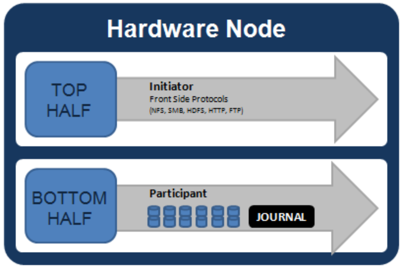
Figure 5. Model of node components involved in I/O
If we were to look at all the components within every node of a cluster that are involved in I/O from a high level, it would look like Figure 5. We have split the stack into a “top” layer, called the Initiator, and a “bottom” layer, called the Participant. This division is used as a “logical model” for the analysis of any one given read or write. At a physical-level, CPUs and RAM cache in the nodes are simultaneously handling Initiator and Participant tasks for I/O taking place throughout the cluster. There are caches and a distributed lock manager that are excluded from the diagram above to keep it simple. They will be covered in later sections of the paper.
When a client connects to a node to write a file, it is connecting to the top half or Initiator of that node. Files are broken into smaller logical chunks called stripes before being written to the bottom half or Participant of a node (disk). Failure-safe buffering using a write coalescer is used to ensure that writes are efficient and read-modify-write operations are avoided. The size of each file chunk is referred to as the stripe unit size.
OneFS stripes data across all nodes—and not simply across disks—and protects the files, directories, and associated metadata using software erasure-code or mirroring technology. For data, OneFS can use (at the administrator’s discretion) either the Reed-Solomon erasure coding system for data protection, or (less commonly) mirroring. Mirroring, when applied to user data, tends to be used more for high-transaction performance cases. The bulk of user data will generally use erasure coding, as it provides extremely high performance without sacrificing on-disk efficiency. Erasure coding can provide beyond 80% efficiency on raw disk with five nodes or more, and on large clusters can even do so while providing quadruple-level redundancy. The stripe width for any given file is the number of nodes (not drives) that a file is written across. It is determined by the number of nodes in the cluster, the size of the file, and the protection setting (for example, +2n).
OneFS uses advanced algorithms to determine data layout for maximum efficiency and performance. When a client connects to a node, that node’s initiator acts as the “captain” for the write data layout of that file. Data, erasure code (ECC) protection, metadata, and inodes are all distributed on multiple nodes within a cluster, and even across multiple drives within nodes.
The following figure shows a file write happening across all nodes in a three-node cluster.
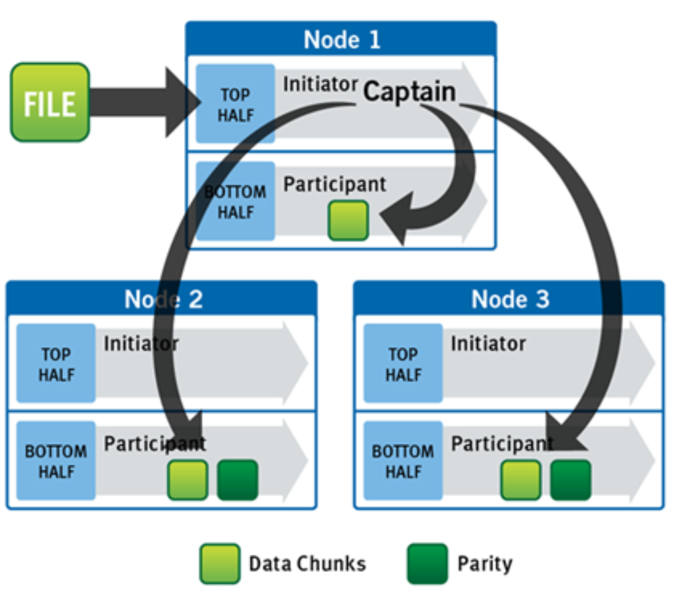
Figure 6. A file write operation on a 3-node cluster
OneFS uses the back-end network to allocate and stripe data across all nodes in the cluster automatically, so no additional processing is required. As data is being written, it is being protected at the specified level. When writes take place, OneFS divides data out into atomic units called protection groups. Redundancy is built into protection groups, such that if every protection group is safe, then the entire file is safe. For files protected by erasure codes, a protection group consists of a series of data blocks as well as a set of erasure codes for those data blocks; for mirrored files, a protection group consists of all of the mirrors of a set of blocks. OneFS can switch the type of protection group used in a file dynamically, as it is writing. This can allow many additional functionalities including, for example, allowing the system to continue without blocking in situations when temporary node failures in the cluster would prevent the wanted number of erasure codes from being used. Mirroring can be used temporarily in these cases to allow writes to continue. When nodes are restored to the cluster, these mirrored protection groups are converted back seamlessly and automatically to erasure-code-protected, without administrator intervention.
The OneFS file system block size is 8 KB. A file smaller than 8 KB will use a full 8 KB block. Depending on the data protection level, this 8KB file could end up using more than 8KB of data space. However, data protection settings are discussed in detail in a later section of this paper. OneFS can support file systems with billions of small files at very high performance, because all the on-disk structures are designed to scale to such sizes and provide near-instantaneous access to any one object regardless of the total number of objects. For larger files, OneFS can take advantage of using multiple, contiguous 8 KB blocks. In these cases, up to sixteen contiguous blocks can be striped onto a single node’s disk. If a file is 32 KB in size, then four contiguous 8 KB blocks will be used.
For even larger files, OneFS can maximize sequential performance by taking advantage of a stripe unit consisting of 16 contiguous blocks, for a total of 128 KB per stripe unit. During a write, data is broken into stripe units and these are spread across multiple nodes as a protection group. As data is being laid out across the cluster, erasure codes or mirrors, as required, are distributed within each protection group to ensure that files are always protected.
One of the key functions of the AutoBalance functionality of OneFS is to reallocate and rebalance data and make storage space more usable and efficient, when possible. In most cases, the stripe width of larger files can be increased to take advantage of new free space (as nodes are added) and to make the on-disk striping more efficient. AutoBalance maintains high on-disk efficiency and eliminates on-disk “hot spots” automatically.
The initiator top half of the “captain” node uses a modified two-phase commit transaction to safely distribute writes to multiple NVRAMs across the cluster, as shown in the following figure.
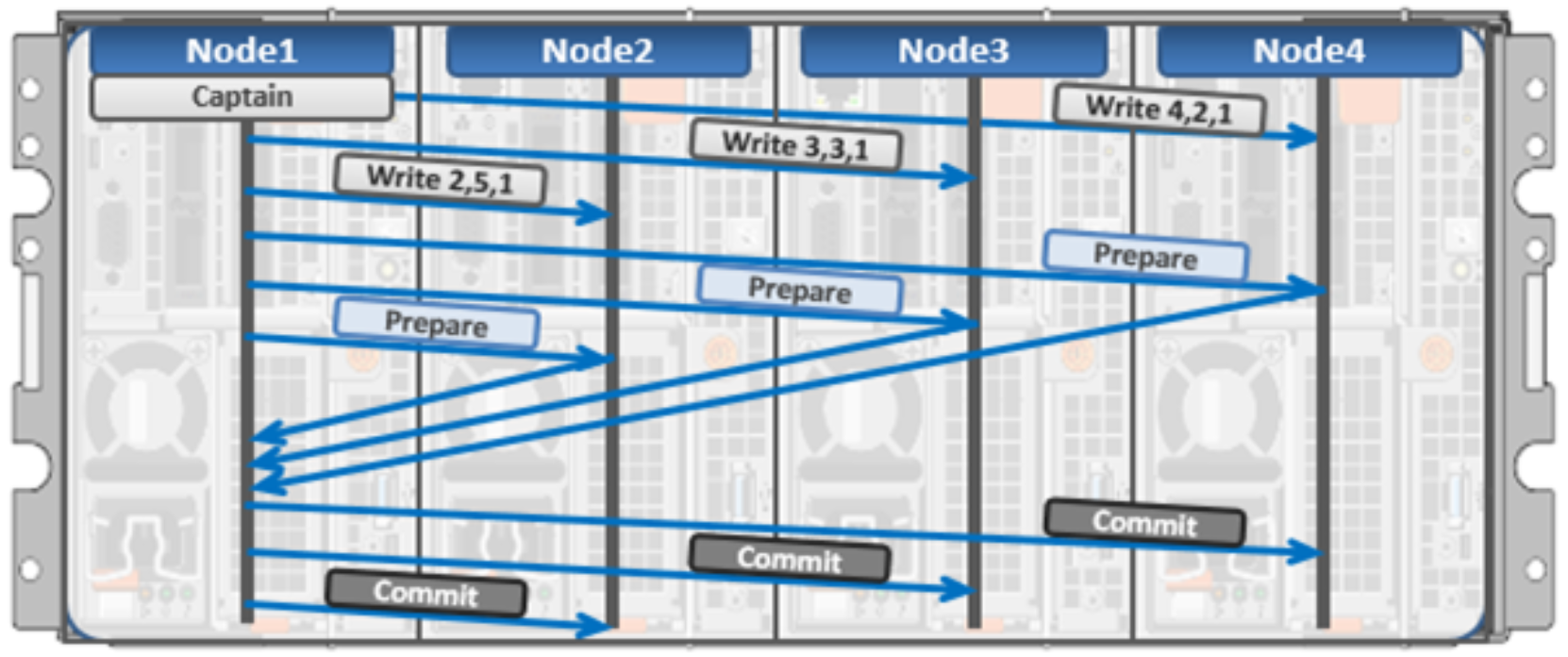
Figure 7. Distributed transactions and two-phase commit
Every node that owns blocks in a particular write is involved in a two-phase commit. The mechanism relies on NVRAM for journaling all the transactions that are occurring across every node in the storage cluster. Using multiple NVRAMs in parallel allows for high-throughput writes while maintaining data safety against all manner of failures, including power failures. In the event that a node should fail mid-transaction, the transaction is restarted instantly without that node involved. When the node returns, the only required actions are for the node to replay its journal from NVRAM—which takes seconds or minutes—and, occasionally, for AutoBalance to rebalance files that were involved in the transaction. No expensive ‘fsck’ or ‘disk-check’ processes are ever required. No drawn-out resynchronization ever needs to take place. Writes are never blocked due to a failure. This patented transaction system is one of the ways that OneFS eliminates single—and even multiple—points of failure.
In a write operation, the initiator “captains” or orchestrates the layout of data and metadata, the creation of erasure codes, and the normal operations of lock management and permissions control. An administrator from the web management or CLI interface at any point can optimize layout decisions made by OneFS to better suit the workflow. The administrator can choose from the access patterns below at a per-file or directory-level:
- Concurrency: Optimizes for current load on the cluster, featuring many simultaneous clients. This setting provides the best behavior for mixed workloads.
- Streaming: Optimizes for high-speed streaming of a single file, for example to enable very fast reading with a single client.
- Random: Optimizes for unpredictable access to the file, by adjusting striping and disabling the use of any prefetch cache.
OneFS also includes real-time adaptive prefetch, providing the optimal read performance for files with a recognizable access pattern, without any administrative intervention. OneFS 9.5 extends prefetching by adding a metadata prefetcher and a lock prefetcher for streaming and concurrency performance.
Note: The largest file size that OneFS currently supports is increased to 16 TB in OneFS 8.2.2 and later, up from a maximum of 4 TB in prior releases.
OneFS caching
The OneFS caching infrastructure design is predicated on aggregating the cache present on each node in a cluster into one globally accessible pool of memory. To do this, OneFS uses an efficient messaging system, similar to non-uniform memory access (NUMA). This allows all the nodes’ memory cache to be available to each and every node in the cluster. Remote memory is accessed over an internal interconnect and has much lower latency than accessing hard disk drives.
For remote memory access, OneFS uses a redundant, under-subscribed flat Ethernet network, as, essentially, a distributed system bus. While not as fast as local memory, remote memory access is still very fast due to the low latency of 40Gb and 100Gb Ethernet.
The OneFS caching subsystem is coherent across the cluster. This means that if the same content exists in the private caches of multiple nodes, this cached data is consistent across all instances. OneFS uses the MESI Protocol to maintain cache coherency. This protocol implements an “invalidate-on-write” policy to ensure that all data is consistent across the entire shared cache.
OneFS uses up to three levels of read cache, plus an NVRAM-backed write cache, or coalescer. These, and their high-level interaction, are illustrated in the following diagram.
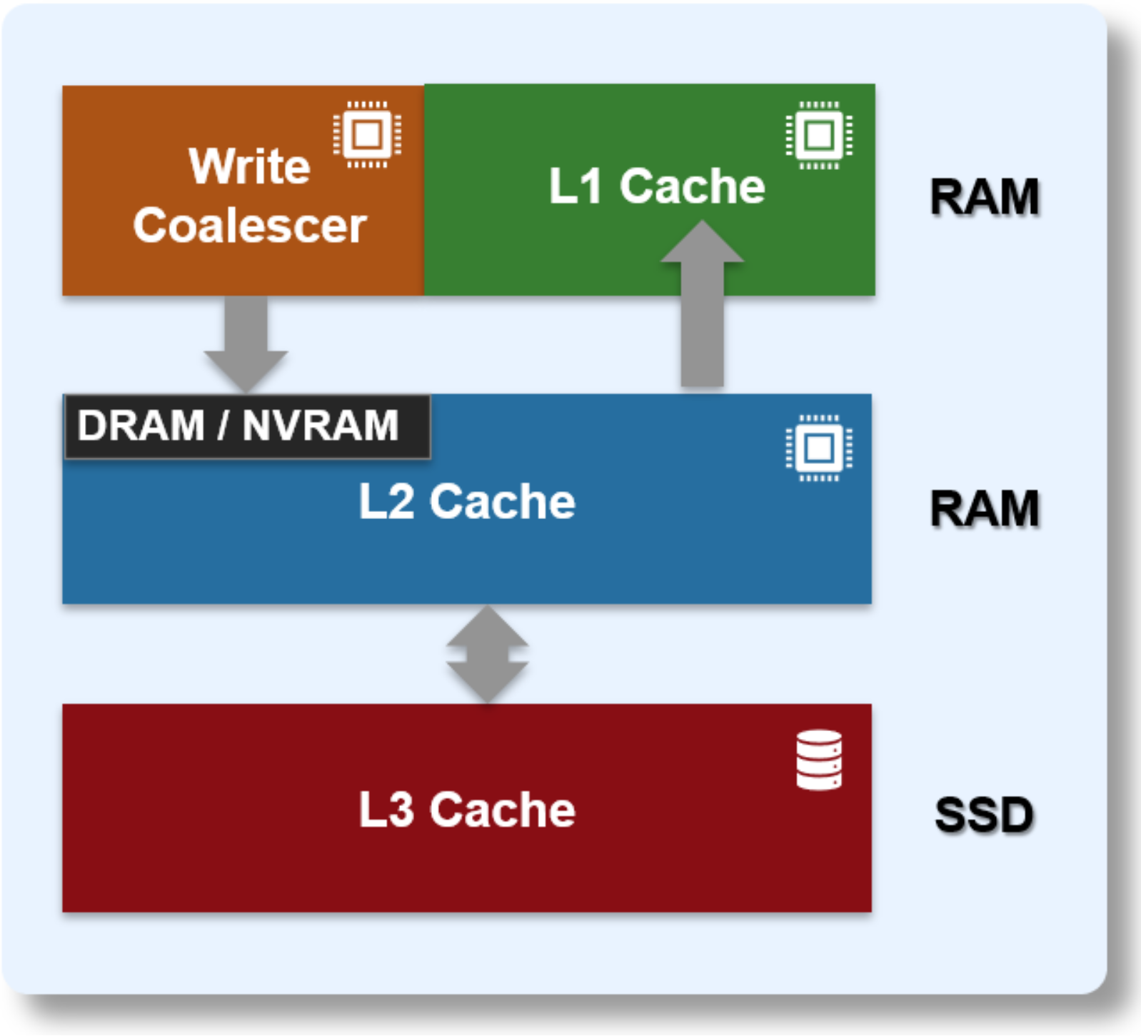
Figure 8. OneFS caching hierarchy
The first two types of read cache, level 1 (L1) and level 2 (L2), are memory (RAM) based and analogous to the cache used in processors (CPUs). These two cache layers are present in all platform storage nodes.
Table 2. OneFS cache
Name
Type
Persistence
Description
L1 Cache
RAM
Volatile
Also called front-end cache, holds clean, cluster coherent copies of file system data and metadata blocks requested by clients over the front-end network
L2 Cache
RAM
Volatile
Back-end cache, containing clean copies of file system data and metadata on a local node
SmartCache /
Write Coalescer
NVRAM
Non-volatile
Persistent, battery backed NVRAM journal cache which buffers any pending writes to front-end files that have not been committed to disk.
SmartFlash
L3 Cache
SSD
Non-volatile
Contains file data and metadata blocks evicted from L2 cache, effectively increasing L2 cache capacity.
OneFS cache coherency
The OneFS caching subsystem is coherent across the cluster. This means that if the same content exists in the private caches of multiple nodes, this cached data is consistent across all instances. For example, consider the following initial state and sequence of events:
- Node 1 and Node 5 each have a copy of data located at an address in shared cache.
- Node 5, in response to a write request, invalidates node 1’s copy.
- Node 5 then updates the value. (See below).
- Node 1 must re-read the data from shared cache to get the updated value.
OneFS uses the MESI Protocol to maintain cache coherency. This protocol implements an “invalidate-on-write” policy to ensure that all data is consistent across the entire shared cache. The following diagram illustrates the various states that in-cache data can take, and the transitions between them. The various states in the figure are:
- M – Modified: The data exists only in local cache and has been changed from the value in shared cache. Modified data is typically referred to as dirty.
- E – Exclusive: The data exists only in local cache but matches what is in shared cache. This data is often referred to as clean.
- S – Shared: The data in local cache may also be in other local caches in the cluster.
- I – Invalid: A lock (exclusive or shared) has been lost on the data.
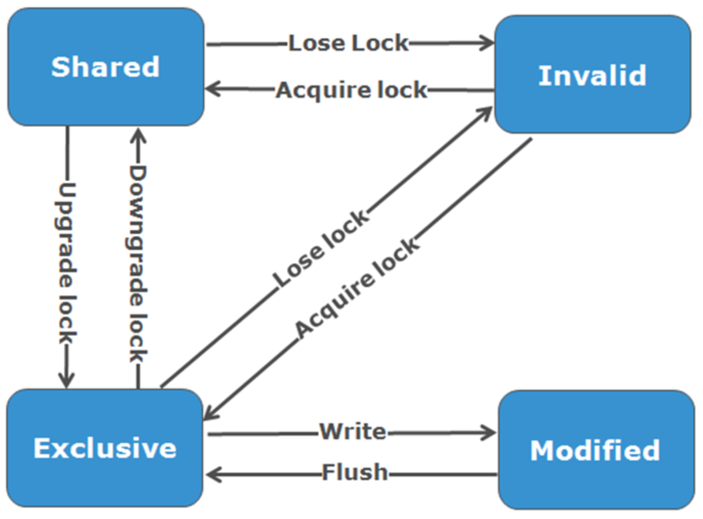
Figure 9. OneFS cache coherency state diagram
Level 1 cache
The Level 1 cache (L1), or front-end cache, is memory that is nearest to the protocol layers (for example NFS or SMB) used by clients, or initiators, connected to that node. The primary purpose of L1 cache is to prefetch data from remote nodes. Data is prefetched per file, and this is optimized in order to reduce the latency associated with the nodes’ back-end network. Since the backend interconnect latency is relatively small, the size of L1 cache, and the typical amount of data stored per request, is less than L2 cache.
L1 is also known as remote cache because it contains data retrieved from other nodes in the cluster. It is coherent across the cluster but is used only by the node on which it resides and is not accessible by other nodes. Data in L1 cache on storage nodes is aggressively discarded after it is used. L1 cache uses file-based addressing, in which data is accessed by an offset into a file object.
The L1 cache refers to memory on the same node as the initiator. It is only accessible to the local node, and typically the cache is not the primary copy of the data. This is analogous to the L1 cache on a CPU core, which may be invalidated as other cores write to main memory.
L1 cache coherency is managed using a MESI-like protocol using distributed locks, as described above.
OneFS also uses a dedicated inode cache in which recently requested inodes are kept. The inode cache frequently has a large impact on performance, because clients often cache data, and many network I/O activities are primarily requests for file attributes and metadata, which can be quickly returned from the cached inode.
L1 cache is used differently in cluster Accelerator nodes, which do not contain any disk drives. Instead, the entire read cache is L1 cache, since all the data is fetched from other storage nodes. Also, cache aging is based on a least recently used (LRU) eviction policy, as opposed to the drop-behind algorithm typically used in a storage node’s L1 cache. Because an accelerator’s L1 cache is large, and the data in it is much more likely to be requested again, so data blocks are not immediately removed from cache upon use. However, metadata and update heavy workloads do not benefit as much, and an accelerator’s cache is only beneficial to clients directly connected to the node.
Level 2 cache
The Level 2 cache (L2), or back-end cache, refers to local memory on the node on which a particular block of data is stored. L2 cache is globally accessible from any node in the cluster and is used to reduce the latency of a read operation by not requiring a seek directly from the disk drives. As such, the amount of data prefetched into L2 cache for use by remote nodes is much greater than that in L1 cache.
L2 cache is also known as local cache because it contains data retrieved from disk drives located on that node and then made available for requests from remote nodes. Data in L2 cache is evicted according to a Least Recently Used (LRU) algorithm.
Data in L2 cache is addressed by the local node using an offset into a disk drive which is local to that node. Since the node knows where the data requested by the remote nodes is located on disk, this is a very fast way of retrieving data destined for remote nodes. A remote node accesses L2 cache by doing a lookup of the block address for a particular file object. As described above, there is no MESI invalidation necessary here and the cache is updated automatically during writes and kept coherent by the transaction system and NVRAM.
Level 3 cache
An optional third tier of read cache, called SmartFlash or Level 3 cache (L3), is also configurable on nodes that contain solid state drives (SSDs). SmartFlash (L3) is an eviction cache that is populated by L2 cache blocks as they are aged out from memory. There are several benefits to using SSDs for caching rather than as traditional file system storage devices. For example, when reserved for caching, the entire SSD will be used, and writes will occur in a very linear and predictable way. This provides far better utilization and also results in considerably reduced wear and increased durability over regular file system usage, particularly with random write workloads. Using SSD for cache also makes sizing SSD capacity a much more straightforward and less error prone prospect compared to using use SSDs as a storage tier.
The following diagram illustrates how clients interact with the OneFS read cache infrastructure and the write coalescer. L1 cache still interacts with the L2 cache on any node it requires, and the L2 cache interacts with both the storage subsystem and L3 cache. L3 cache is stored on an SSD within the node and each node in the same node pool has L3 cache enabled.
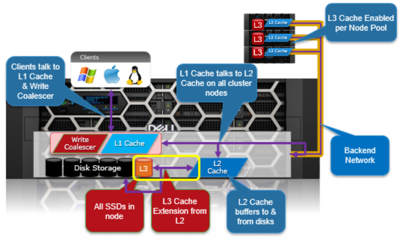
Figure 10. OneFS L1, L2, and L3 caching architecture
OneFS dictates that a file is written across multiple nodes in the cluster, and possibly multiple drives within a node, so all read requests involve reading remote (and possibly local) data. When a read request arrives from a client, OneFS determines whether the requested data is in local cache. Any data resident in local cache is read immediately. If data requested is not in local cache, it is read from disk. For data not on the local node, a request is made from the remote nodes on which it resides. On each of the other nodes, another cache lookup is performed. Any data in the cache is returned immediately, and any data not in the cache is retrieved from disk.
When the data has been retrieved from local and remote cache (and possibly disk), it is returned back to the client.
The high-level steps for fulfilling a read request on both a local and remote node are:
On local node (the node receiving the request):
- Determine whether part of the requested data is in the local L1 cache. If so, return to client.
- If not in the local cache, request data from the remote node(s).
On remote nodes:
- Determine whether requested data is in the local L2 or L3 cache. If so, return to the requesting node.
- If not in the local cache, read from disk and return to the requesting node.
Write caching accelerates the process of writing data to a cluster. This is achieved by batching up smaller write requests and sending them to disk in bigger chunks, removing a significant amount of disk writing latency. When clients write to the cluster, OneFS temporarily writes the data to an NVRAM-based journal cache on the initiator node, instead of immediately writing to disk. OneFS can then flush these cached writes to disk at a later, more convenient time. Also, these writes are also mirrored to participant nodes’ NVRAM journals to satisfy the file’s protection requirement. If there is a cluster split or unexpected node outage, uncommitted cached writes are fully protected.
The write cache operates as follows:
- An NFS client sends Node 1 a write request for a file with +2n protection.
- Node 1 accepts the writes into its NVRAM write cache (fast path) and then mirrors the writes to participant nodes’ log files for protection.
- Write acknowledgments are returned to the NFS client immediately and as such, write to disk latency is avoided.
- As Node 1’s write cache fills, it is periodically flushed, and writes are committed to disk using the two-phase commit process (described above) with the appropriate erasure code (ECC) protection applied (+2n).
- The write cache and participant node log files are cleared and available to accept new writes.
Further information is available in the OneFS SmartFlash white paper.
File reads
Data, metadata, and inodes are all distributed on multiple nodes within a cluster, and even across multiple drives within nodes. When reading or writing to the cluster, the node a client attaches to acts as the “captain” for the operation.
In a read operation, the “captain” node gathers all of the data from the various nodes in the cluster and presents it in a cohesive way to the requestor.
Due to the use of cost-optimized industry standard hardware, the cluster provides a high ratio of cache to disk (multiple GB per node) that is dynamically allocated for read and write operations as needed. This RAM-based cache is unified and coherent across all nodes in the cluster, allowing a client read request on one node to benefit from I/O already transacted on another node. These cached blocks can be quickly accessed from any node across the low-latency backplane, allowing for a large, efficient RAM cache, which greatly accelerates read performance.
As the cluster grows larger, the cache benefit increases. For this reason, the amount of I/O to disk on a cluster is generally substantially lower than it is on traditional platforms, allowing for reduced latencies and a better user experience.
For files marked with an access pattern of concurrent or streaming, OneFS can take advantage of pre-fetching of data based on heuristics used by the SmartRead component. SmartRead can create a data “pipeline” from L2 cache, prefetching into a local “L1” cache on the “captain” node. This greatly improves sequential-read performance across all protocols and means that reads come directly from RAM within milliseconds. For high-sequential cases, SmartRead can aggressively prefetch ahead, allowing reads or writes of individual files at high data rates.
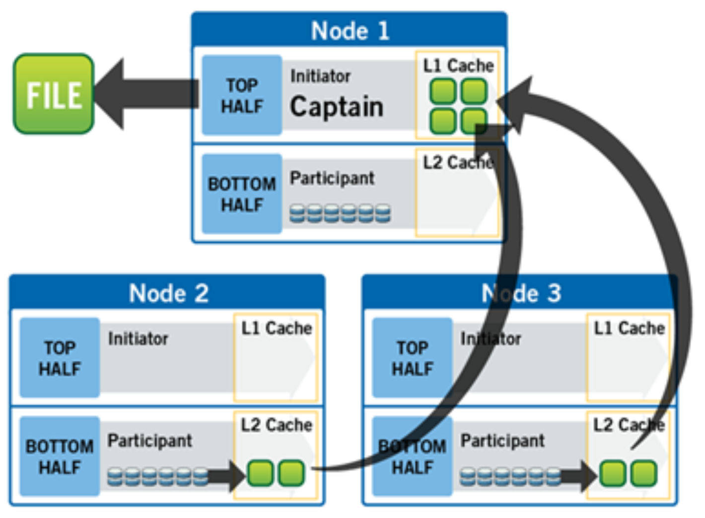
Figure 11. A file read operation on a 3-node cluster
Figure 11 illustrates how SmartRead reads a sequentially accessed, non-cached file that is requested by a client attached to Node1 in a 3-node cluster.
- Node1 reads metadata to identify where all the blocks of file data exist.
- Node1 also checks its L1 cache to see if it has the file data being requested.
- Node1 builds a read pipeline, sending concurrent requests to all nodes that have a piece of file data to retrieve that file data from disk.
- Each node pulls the blocks of file data from disk into their L2 cache (or L3 SmartFlash cache, when available), and transmits the file data to Node1.
- Node1 records the incoming data to L1 cache, simultaneously serving the file to the client. Meanwhile, the pre-fetching process continues.
- For highly sequential cases, data in L1 cache may be optionally “dropped behind” to free RAM for other L1 or L2 cache demands.
SmartRead’s intelligent caching allows for very high read performance with high levels of concurrent access. Importantly, it is faster for Node1 to get file data from the cache of Node2 (over the low-latency cluster interconnect) than to access its own local disk. SmartRead’s algorithms control how aggressive the pre-fetching is (disabling pre-fetch for random-access cases) and how long data stays in the cache and optimizes where data is cached.
For streaming reads from low-latency SSD media, the cache benefit of prefetching is typically less than the overhead. Therefore, OneFS 9.5 automatically disables L2 cache prefetching for concurrent and streaming reads from SSD media but still uses L2 caching when prefetching data blocks from spinning disk (HDD).
Locks and concurrency
OneFS has a fully distributed lock manager that marshals locks on data across all nodes in a storage cluster. The locking manager is highly extensible and allows for multiple lock “personalities” to support both file system locks and cluster-coherent protocol-level locks such as SMB share mode locks or NFS advisory-mode locks. OneFS also has support for delegated locks such as CIFS oplocks and NFSv4 delegations.
Every node in a cluster is a coordinator for locking resources and a coordinator is assigned to lockable resources based on an advanced hashing algorithm. According to the algorithm’s design, the coordinator almost always ends up on a different node than the initiator of the request. When a lock is requested for a file, it could be a shared lock (allowing multiple users to share the lock simultaneously, usually for reads) or an exclusive lock (allowing one user at any given moment, typically for writes).
Figure 12 illustrates an example of how threads from different nodes could request a lock from the coordinator.
- Node 2 is designated to be the coordinator of these resources.
- Thread 1 from Node 4 and thread 2 from Node 3 request a shared lock on a file from Node 2 simultaneously.
- Node 2 checks if an exclusive lock exists for the requested file.
- If no exclusive locks exist, Node 2 grants thread 1 from Node 4 and thread 2 from Node 3 shared locks on the requested file.
- Node 3 and Node 4 are now performing a read on the requested file.
- Thread 3 from Node 1 requests an exclusive lock for the same file as being read by Node 3 and Node 4.
- Node 2 checks with Node 3 and Node 4 if the shared locks can be reclaimed.
- Node 3 and Node 4 are still reading so Node 2 asks thread 3 from Node 1 to wait for a brief instant.
- Thread 3 from Node 1 blocks until the exclusive lock is granted by Node 2 and then completes the write operation.
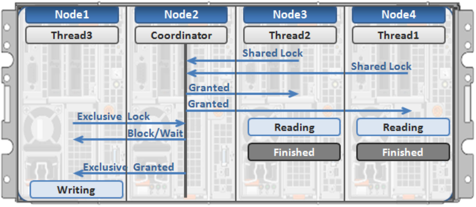
Figure 12. Distributed lock manager
Multi-threaded IO
With the growing use of large NFS datastores for server virtualization and enterprise application support comes the need for high throughput and low latency to large files. To accommodate this, OneFS Multi-writer supports multiple threads concurrently writing to individual files.
In the above example, concurrent write access to a large file can become limited by the exclusive locking mechanism, applied at the whole file level. In order to avoid this potential bottleneck, OneFS Multi-writer provides more granular write locking by sub-diving the file into separate regions and granting exclusive write locks to individual regions, as opposed to the entire file. As such, multiple clients can simultaneously write to different portions of the same file.
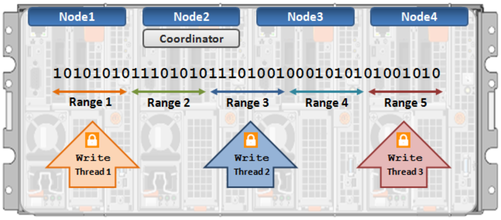
Figure 13. Multi-threaded IO writer