
None
None
-
PowerFlex Manager automates the entire switch configurations along with bond configuration for PowerFlex SO nodes. For PowerFlex Compute Only (CO) nodes, bonding is done on master and worker nodes by applying YAML files. A sample YAML file is available for reference in Appendix.
The following diagram shows the network architecture of this solution:
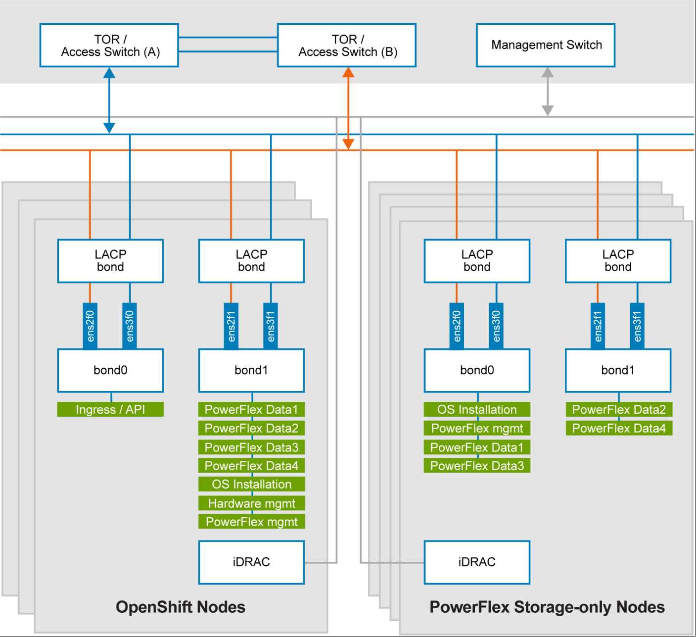
Figure 6. Network design of OpenShift nodes and PowerFlex SO nodes
At the physical layer, two supported Top of Rack (TOR) switches are used for redundancy and load-balancing purposes. A peer link is configured on both the TOR switches. VLANs are created to separate different traffic types on the network bonds.
The following table shows the different networks configured for this solution. For more information, see PowerFlex node VLAN setup:
Table 2. Network details
Network type
VLAN ID
Ingress/API
105
Operating System Installation
104
Hardware Management
101
PowerFlex Management
150
PowerFlex Data 1
152
PowerFlex Data 2
153
PowerFlex Data 3
154
PowerFlex Data 4
155