
Document the current and desired configuration
Document the current and desired configuration
-
As a best practice, it is good to create tables and diagrams like the ones shown in this section as it helps a storage administrator keep track of the components and relationships used in the PowerMax iSCSI environment. Although this is an optional step, detailed documentation greatly helps in management and in communicating the environment details to other teams such as the Networking and Database Administrators.
A table such as the following details the PowerMax parameters and values that comprise the Prod1 environment used in the example.
Table 4. Prod1 Environment PowerMax iSCSI Parameters

The Prod1 environment in this example uses a PowerMax that has two SE directors (1F and 2F). The example shows both directors using a single physical port (port 28). The Prod1 environment will use two storage array iSCSI targets (iqn.dellemc.0536.1F.prod1 and iqn.dellemc.0536.2F.prod1) attached to two IP Interfaces using the IP address of 192.168.82.30 and 192.168.83.30. The Prod1 IP interfaces and targets use two VLANs (82-83) for SAN1 and SAN2. The use of VLANs require that they be set up previously on the network infrastructure by the Networking Team. Other details that are important to document are the switches and switch ports are being used; cable/trunk identifiers; and host information such as host IQNs and CHAP details.
This example uses a Windows Server 2016 host to act as the Prod1 server. In the example, the host name is ENTTME0108 and its initiator IQN is iqn.2001-05.com.mircosoft:enttme0108. In the Solutions Enabler part of the example, One-Way CHAP will be set up for the host initiator on the storage array iSCSI targets.
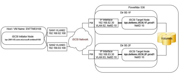
Figure 13. Completed Prod1 Environment Diagram
The above diagram shows how the completed Prod1 environment will look when finished. The components in the diagram correspond with the values shown in the previous Prod1 parameter table.