
None
None
-
This section describes the different types of topologies that make up the solution.
Network topology
At the physical layer, two supported Top of Rack (TOR) switches are used for redundancy and load-balancing purposes. There are four connections from each Dell host, two to TOR A and two to TOR B. Three of the connections are used, one for PowerFlex management and two for PowerFlex data. The data connections are split between the switches.
The following table shows the different networks that are configured for this solution.
Table 3. Network VLANs
Network type
VLAN ID
PowerFlex Management
1109
PowerFlex Data 1
20
PowerFlex Data 2
30
Figure 4 shows a VMware network topology for the Tanzu implementation using the components in this solution: NSX Advanced Load Balancer and vSphere Networking, or more specifically the use of a vSphere Distributed Switch (VDS). The bottom half of the image references the Supervisor Cluster upon which the Tanzu Kubernetes clusters are built. The TKG boxes are the Kubernetes (Guest) cluster.
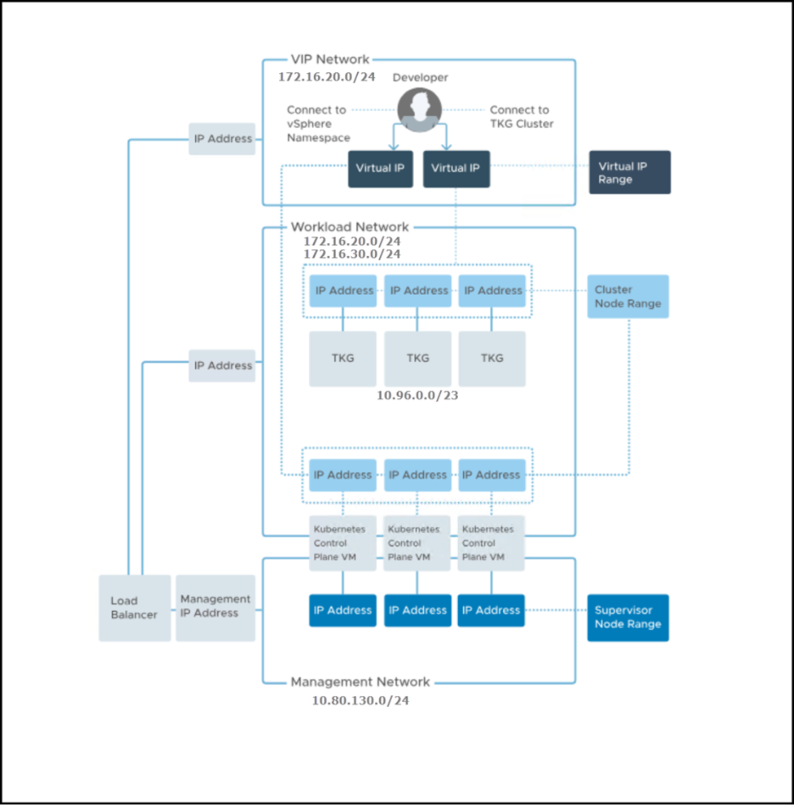
Figure 4. VMware-provided network topology for Tanzu with NSX Advanced Load Balancer
PowerFlex topology
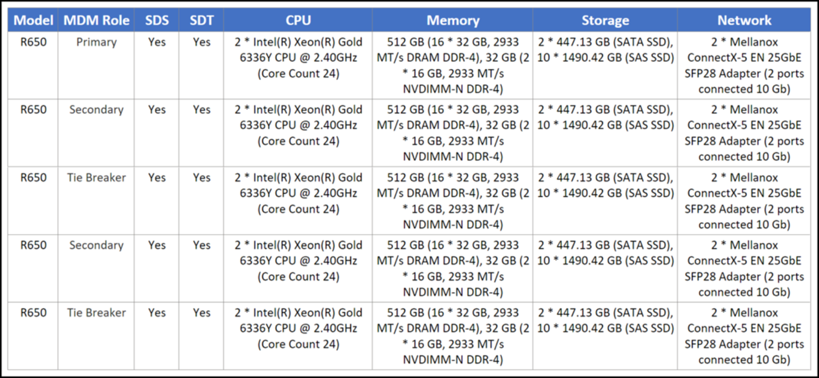
The PowerFlex system consists of five nodes with the characteristics that are covered in Table 4. There is no SDC installed on any of the PowerFlex nodes as the volumes are only mapped to the ESXi hosts.
Table 4. PowerFlex node configurations
VMware topology
The VMware environment is a single vCenter with two clusters, Management and Workload, each with three ESXi hosts with the same configuration as the PowerFlex nodes. A visual depiction is in Figure 5.
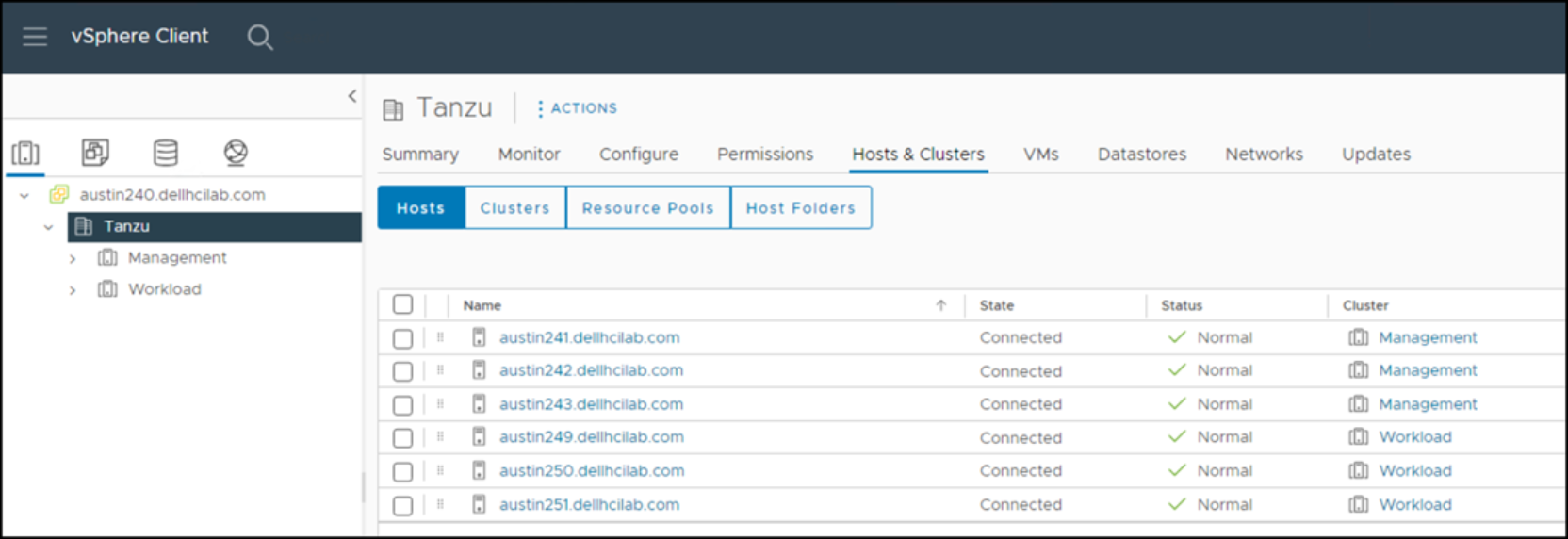
Figure 5. VMware vCenter
Protocol topology
Figure 6 and Figure 7 are logical depictions of the host connectivity between the VMware infrastructure and the PowerFlex. This solution uses both NVMe/TCP and SCSI (SDC) protocols to provision storage to the VMware environment. This concept holds true for both the Tanzu installation and the persistent storage that is created for Tanzu Kubernetes Clusters.
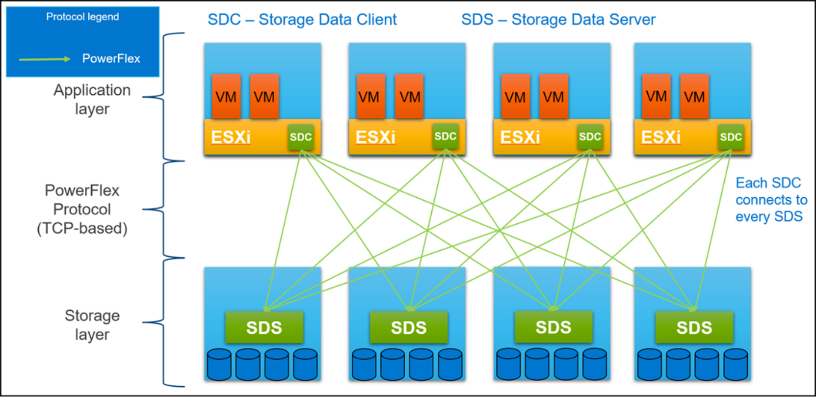
Figure 6. PowerFlex protocol host connectivity
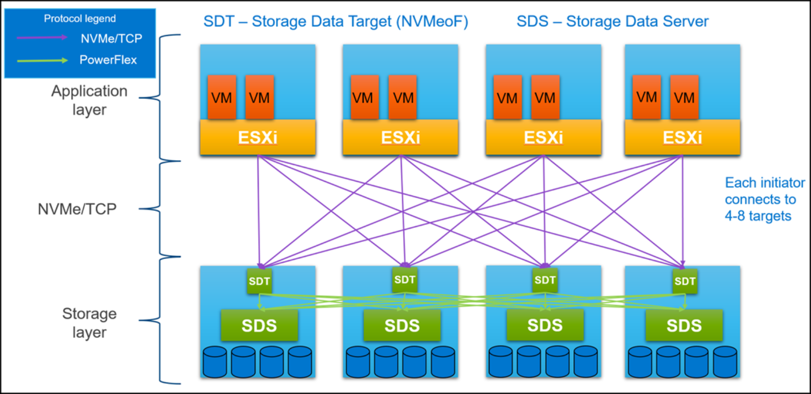
Figure 7. NVMe/TPC protocol host connectivity