
None
None
-
The Supervisor Cluster is configured within vCenter. All steps and images are included as the wizard is likely new for most users.
- In vSphere, click the hamburger menu (
 ) on the left.
 - Go to the Workload Management option.
- Select the Supervisor Clusters tab, and then click ADD CLUSTER.
Figure 59 shows an existing Supervisor Cluster, named Management. This example adds another Supervisor Cluster. Each Supervisor Cluster is associated with a vSphere Cluster of at least two ESXi hosts.
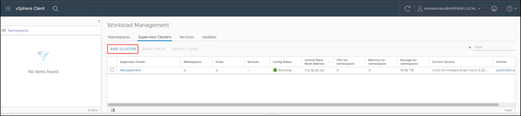
Figure 59. Workload Management – Add Cluster
If there is only a single vCenter it defaults automatically, as shown in Figure 60.
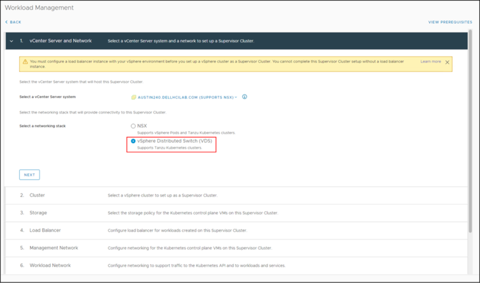
Figure 60. Workload Management – Step 1
- Select the networking stack, as shown in Figure 61.
Note: vSphere Networking is being used in this example. For VDS, a load balancer must already be installed. The wizard requires users to indicate which one in a later step.
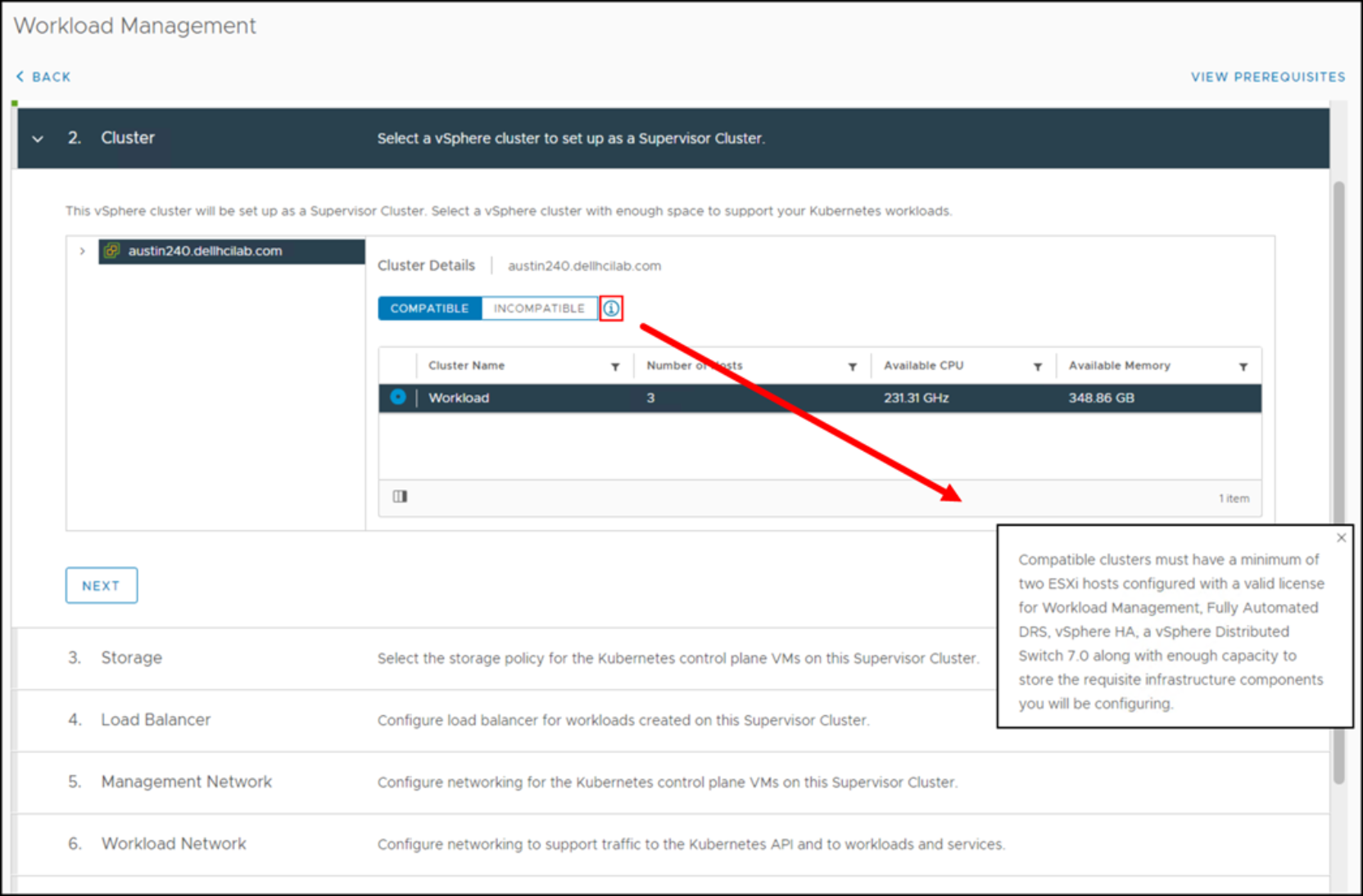
Figure 61. Workload Management – Step 2
- Select a cluster. In this example, there is one remaining cluster with three ESXi hosts.
- Select the information bubble next to the COMPATIBLE button. VMware displays a warning that a minimum of two ESXi hosts are required to create a Supervisor Cluster.
- Use the drop-down box to select a previously created storage policy, either for SDC or NVMe/TCP (as covered in VMware storage policies), as shown in Figure 62.
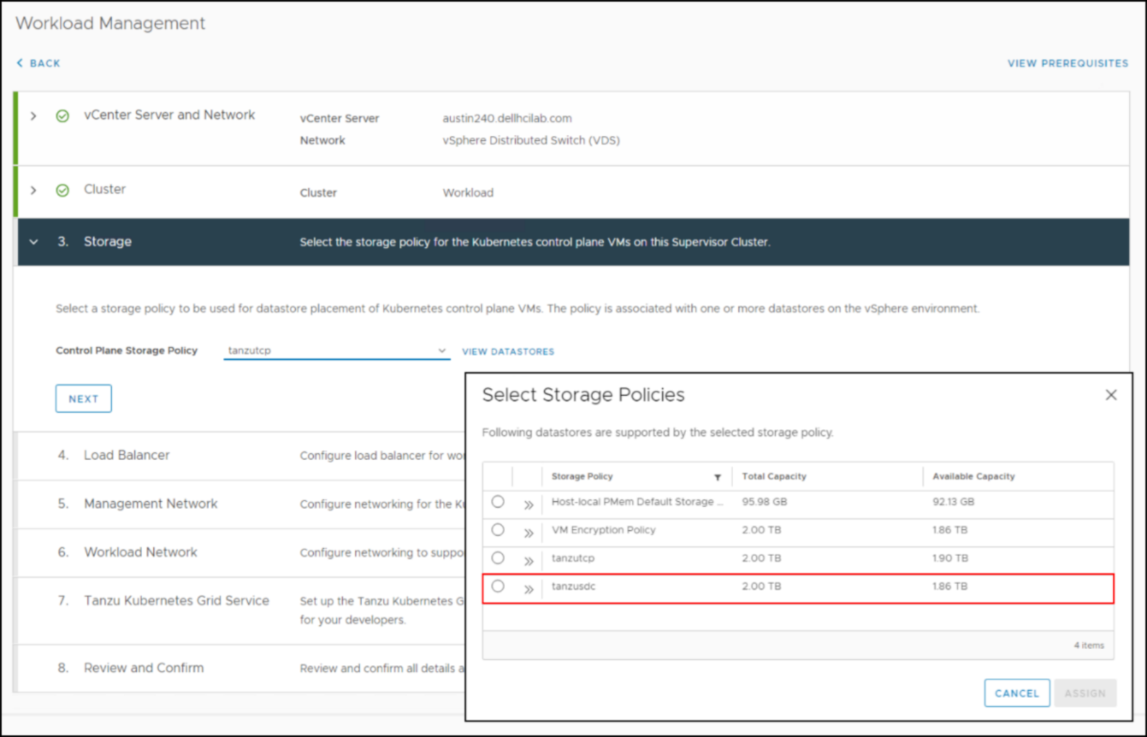
Figure 62. Workload Management – Step 3
Figure 63 indicates that all files that are related to this Supervisor Cluster should be stored in datastores that are tagged with the TCP tag.
- Select the radio button next to the policy. In this example, the tanzutcp storage policy is selected.
- Click ASSIGN to progress to the Load Balancer dialog.
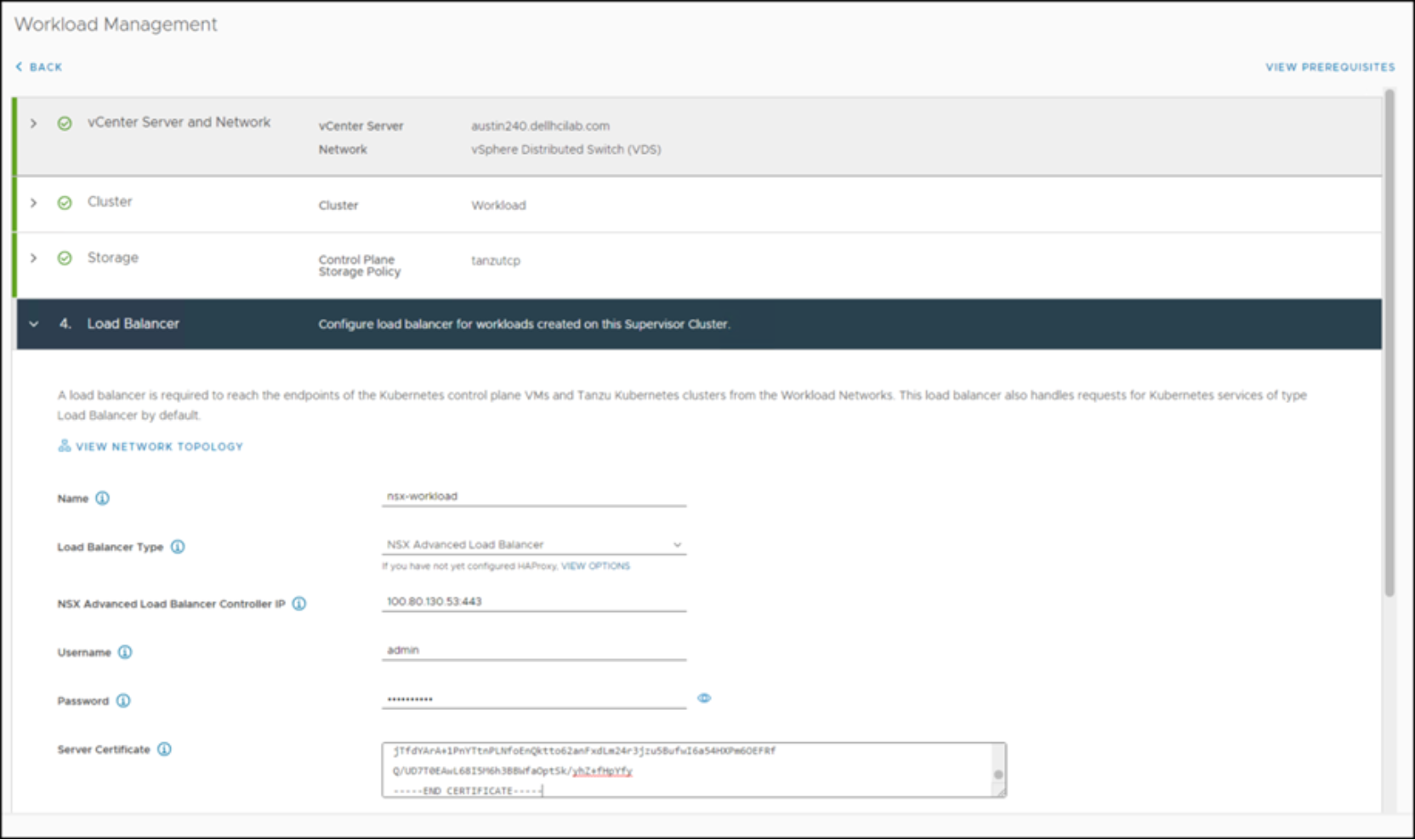
Figure 63. Workload Management – Step 4
The previously created NSX Advanced Load Balancer (ALB) information is required for this step.
- Provide a Name for the ALB.
Note: The name is only an identifier. It is not intended to resolve to an IP, for example.
- Select ALB for the Load Balancer Type.
- Enter the controller IP address. If the ALB is a cluster, use the VIP that was configured when the ALB was installed.
- Enter a Username and Password.
- Paste the Server Certificate into the box that was generated in the ALB.
Note: The certificate information is available within the NSX-ALB interface under Templates -> Security -> SSL/TLS Certificates.
- Expand the Management Network dialog, as shown in Figure 64.
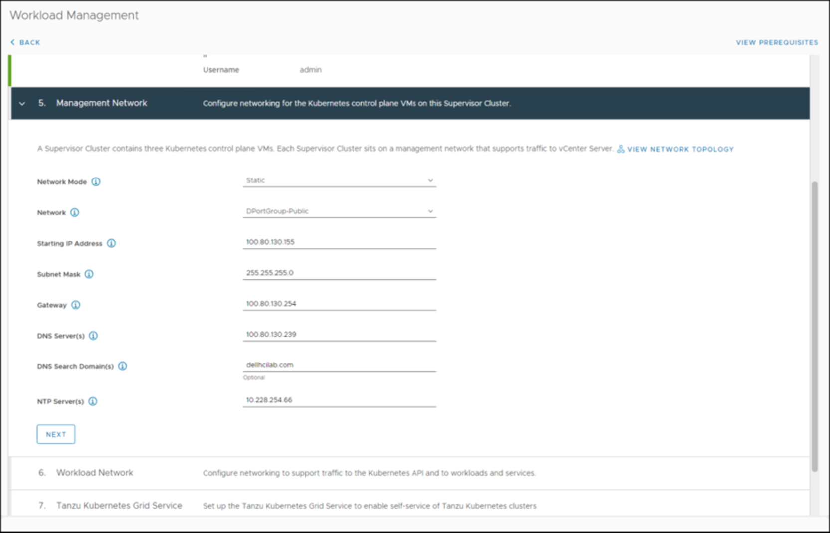
Figure 64. Workload Management – Step 5
- Input the Management Network by selecting either DHCP or Static under Network Mode. In this example, a static configuration is used which necessitates entering all the fields.
- Since a Supervisor Cluster is three nodes, the provided Starting IP Address is the first node.
- The second and third IP addresses are the following two IPs in sequence.
- Expand the Workload Network, as shown in Figure 65.
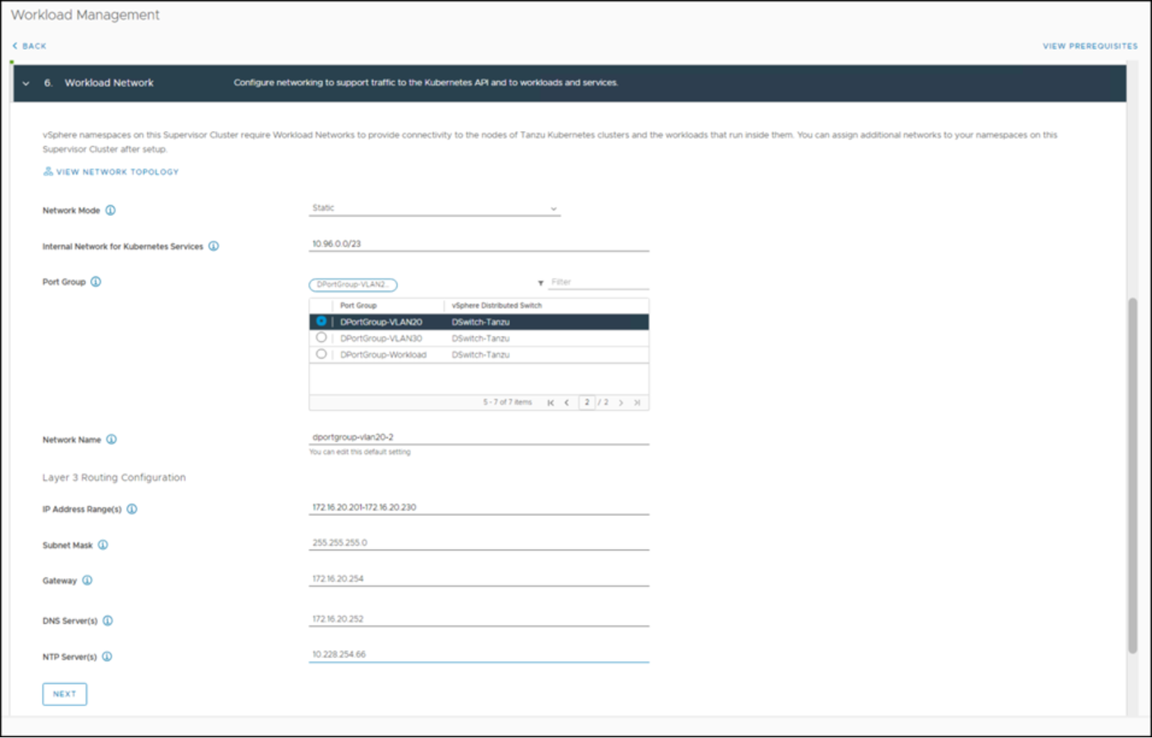
Figure 65. Workload Management – Step 6
The Workload Network is used to communicate with future Kubernetes clusters. Generally, this network is an internal network running on its own VLAN, but it must be able to route to the Management Network. Both static and DHCP routes are supported for the Network Mode.
- Select the Network Mode.
- If using static mode, the CIDR for the Internal Network for Kubernetes Services can be left as default.
- Enter a Network Name. As with ALB, the name is only an identifier.
Note: Be sure to supply enough IP addresses in the IP Address Range to satisfy the intended Kubernetes cluster or clusters.
- Click NEXT to progress to the Content Library dialog, as shown in Figure 66.
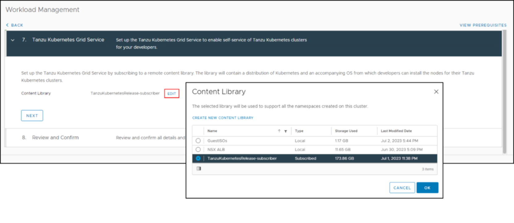
Figure 66. Workload Management – Step 7
- Add the content library that was created in the section Adding a content library.
Doing so enables the Supervisor Cluster to deploy Kubernetes clusters.
- Click OK.
- Click NEXT to progress to the Review and Confirm dialog, as shown in Figure 67.
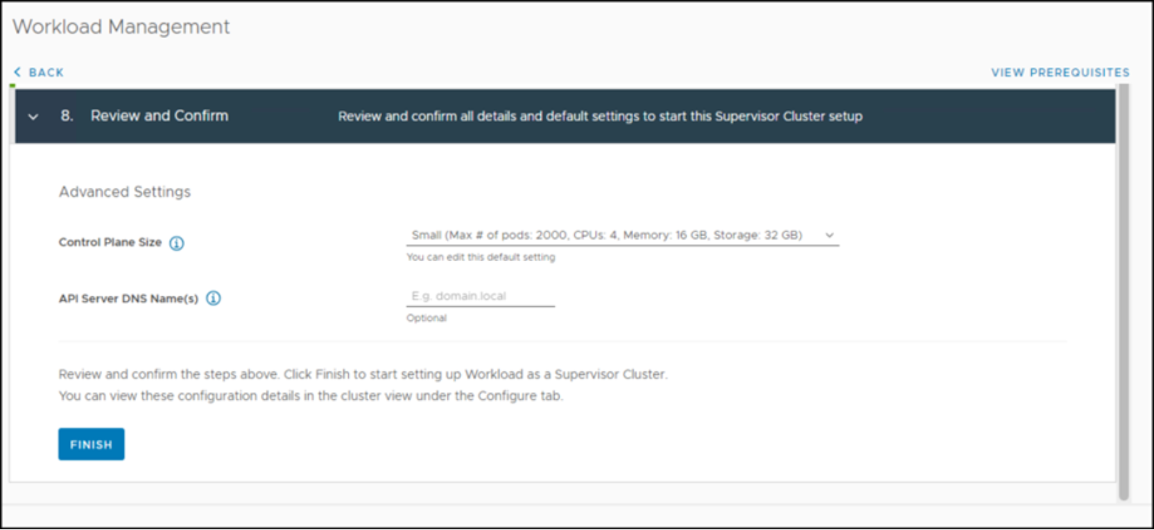
Figure 67. Workload Management – Step 8
- Ensure that all information is correct before proceeding.
Note: If changes are required, then each step in this section must be repeated. You cannot update a single item.
- Once all information is confirmed, click FINISH.
- While the cluster is under configuration, you can review them by selecting the hyperlink (for example, 1) in the Config Status column. The output is shown in Figure 68.
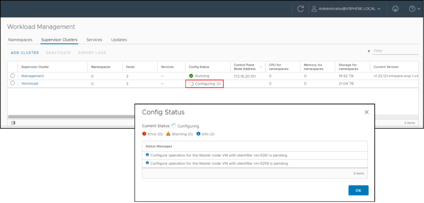
Figure 68. Workload Management – Config Status
The implementation of the Supervisor Cluster can take some time to complete. The Config Status changes to Running when it is done.
Namespace
After creating the Supervisor Cluster, you can create a namespace to manage resources. VMware creates this namespace on the Supervisor Cluster (for example, kubectl create namespace). The VMware namespace enables the administrator to control the resources of the Kubernetes cluster environment.
- In vSphere, go to the Workload cluster and the Namespace tab, as shown in Figure 69.
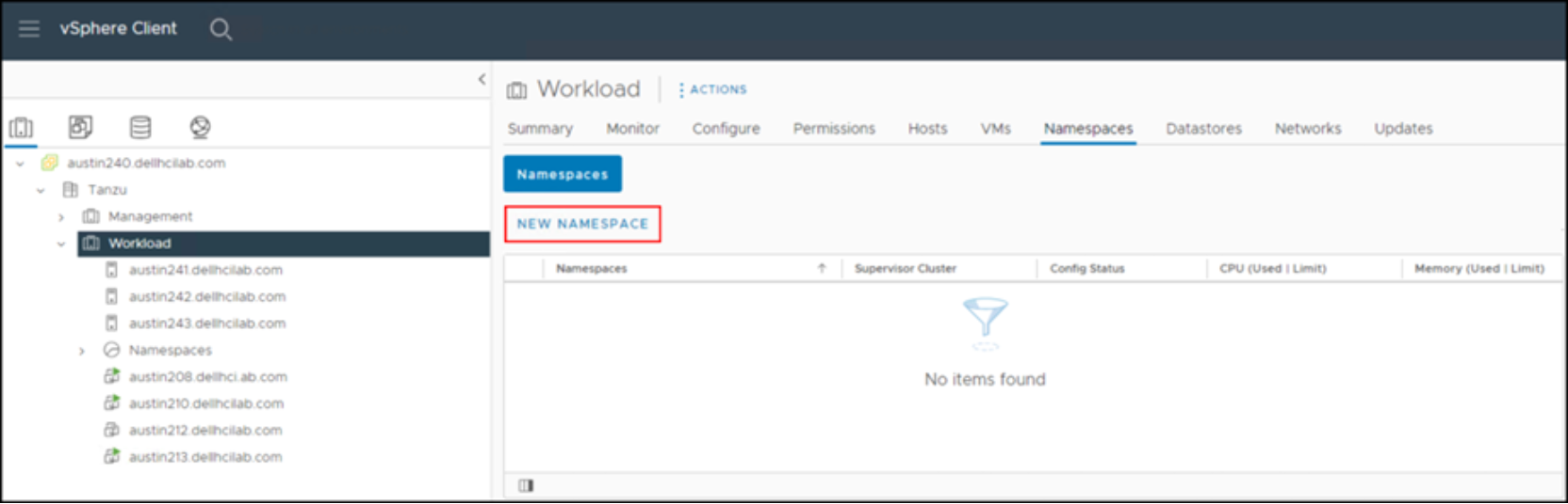
Figure 69. Create namespace – Step 1
- Click NEW NAMESPACE.
Note: This navigation path is one of many possible paths.
- Select the cluster where the namespace should be created. Despite highlighting the cluster, VMware does not default to it. You must select it.
- Enter a Name (required) and a Description (optional) for the namespace.
- Use the drop-down box next to Network to select the appropriate option.
In this example, there is only a single network. If there are multiple workload networks in ALB, they are available as options. See Figure 70.
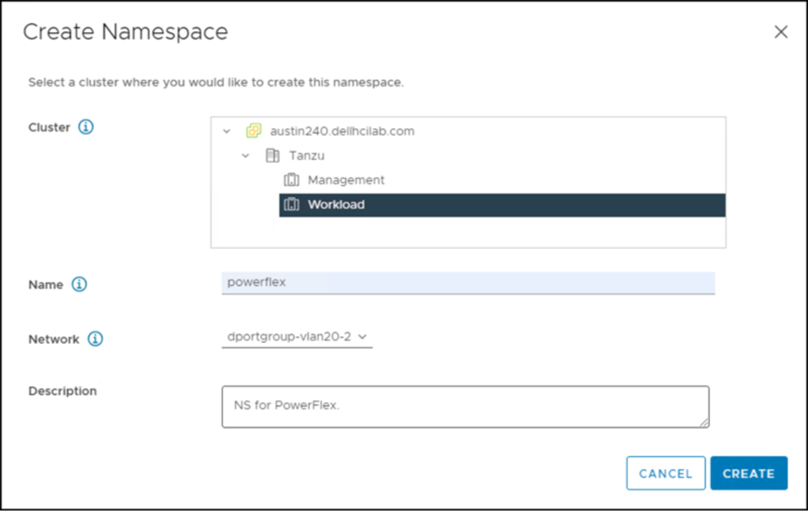
Figure 70. Create namespace – Step 2
The new namespace is immediately available. There are six different sections:
- Status
- Permissions
- Storage
- Capacity and Usage
- Tanzu Kubernetes Grid Service
- VM Service
You can modify many of these categories. Some are covered below.
Note: In the Tanzu Kubernetes Grid Service box, the Content Library is already defined, inheriting the value from the Supervisor Cluster.
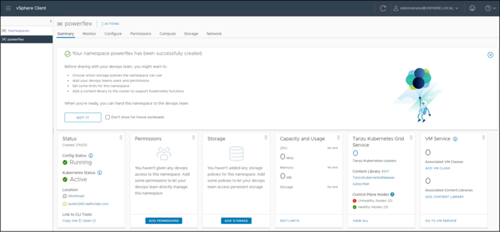
Figure 71. PowerFlex namespace
Permissions
- Provide access to the namespace by clicking ADD PERMISSIONS as shown in Figure 71 above. The Add Permissions dialog appears.
- Grant users or groups permissions to view, edit, or ownership to the namespace.
For example, if a user wants to grant view access to k8 developers from the local domain, the input appears like that shown in Figure 72.
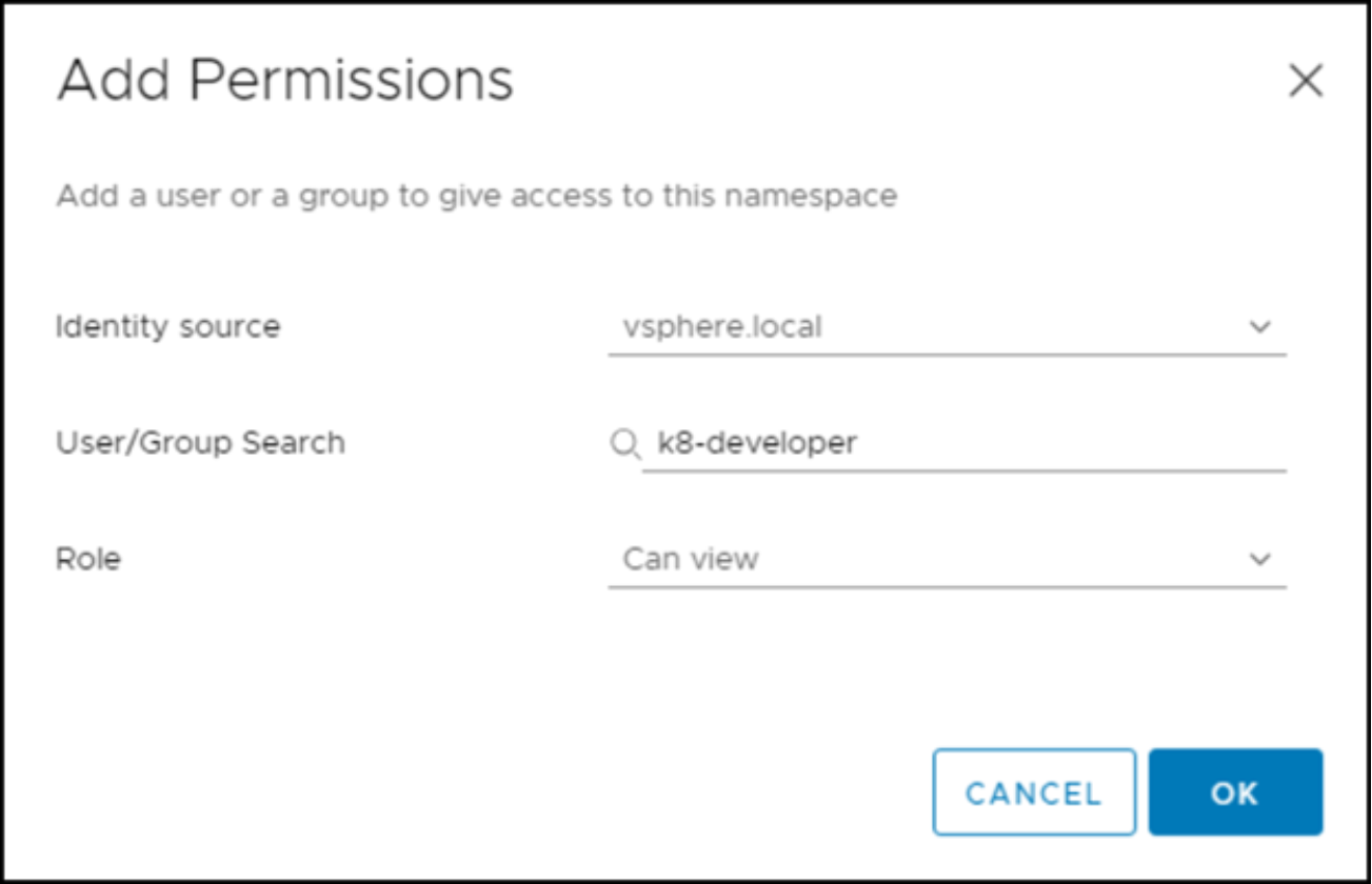
Figure 72. Namespace permissions
- Add all necessary permissions for the namespace before continuing.
Storage
Storage was tagged for the namespaces in the section Namespace tags.
- Provide storage policies for the namespace by clicking ADD STORAGE in the PowerFlex Namespace window (Figure 71 above). The Add Storage dialog appears.
- Select the previously created storage policies - Namespace-TCP, and Namespace-SCSI - in Figure 73.
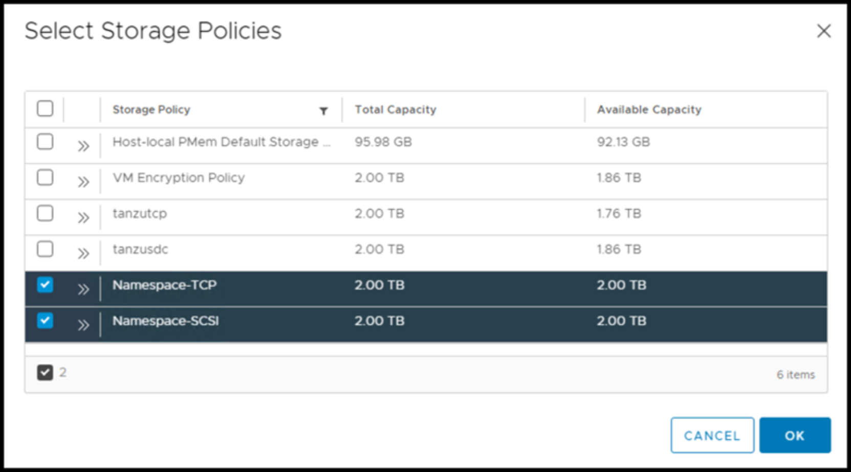
Figure 73. Namespace storage – storage policies
These storage policies are converted to Kubernetes storage classes in the Supervisor Cluster. If you want to give Kubernetes access to any other storage presented to the vCenter, it should be assigned here. Storage policies are the only way to do this access.
- Create any additional storage policies which map to that storage and assign them here. VMware creates the storage classes.
The two storage policies in Figure 73 can be seen during Kubernetes cluster creation.
Capacity and usage
- Provide access to the namespace by clicking EDIT Limits in the Capacity and Usage box in the PowerFlex Namespace window (Figure 71 above).
- Optionally, enter the limitations that you want for CPU, Memory, and Storage. See Figure 74.
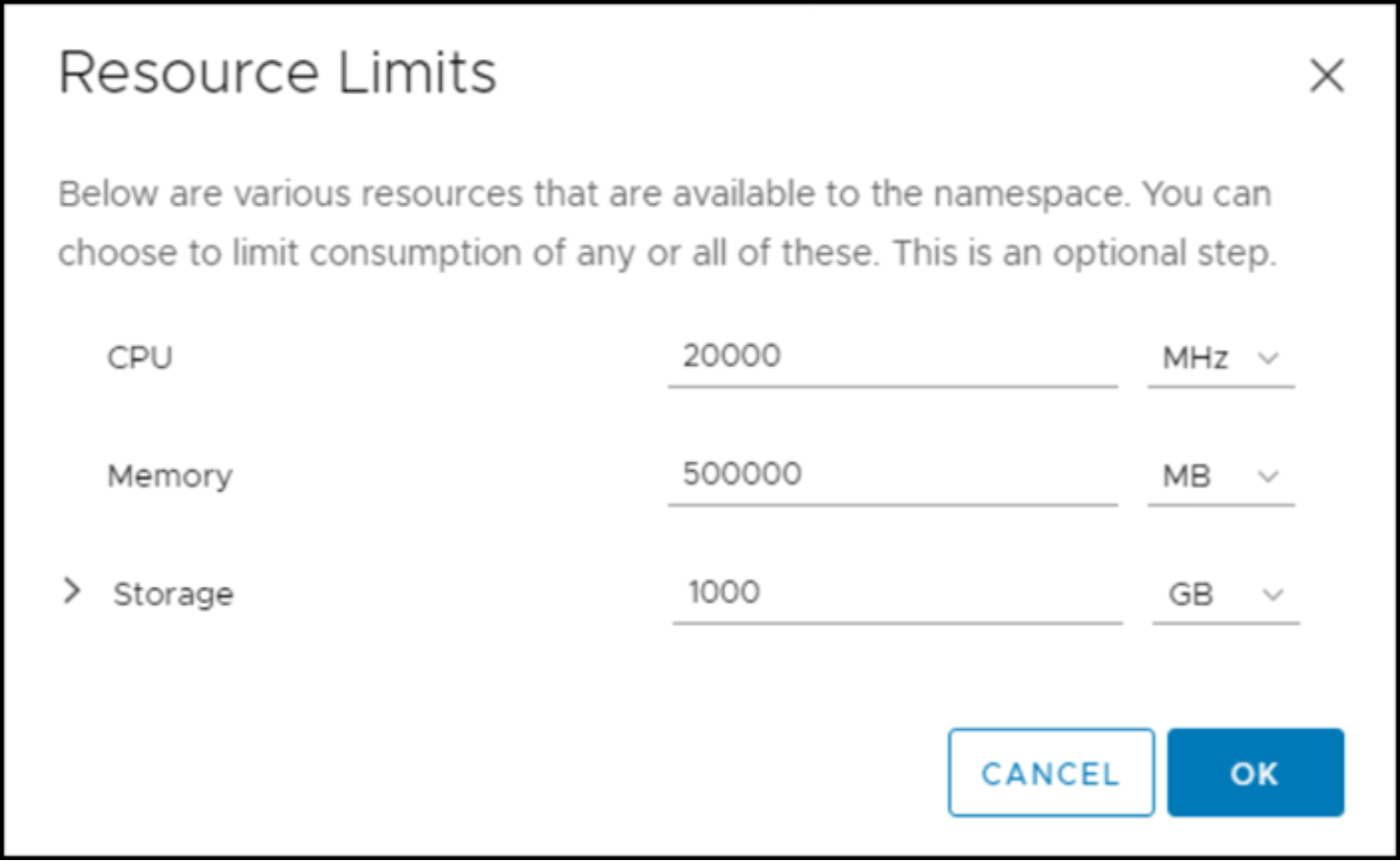
Figure 74. Namespace capacity and usage – Edit limits
VM Service
Finally, you must add some VM Classes which are used when creating Kubernetes clusters in the namespace. This step is mandatory.
- Click ADD VM CLASS in the PowerFlex Namespace window (Figure 71 above) to display the Manage VM Classes window, as shown in Figure 75.
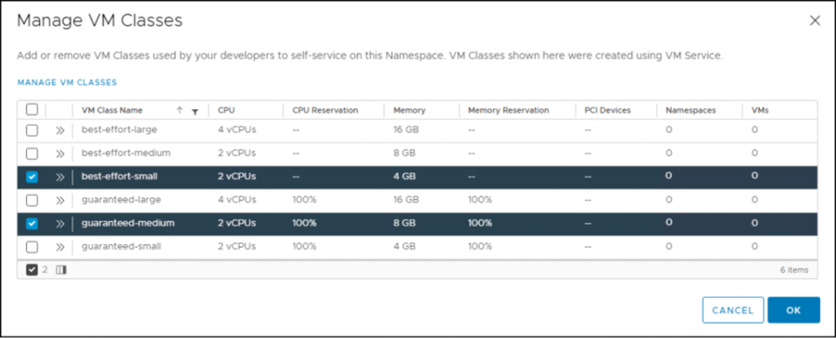
Figure 75. Manage VM Classes
- Use the checkboxes to select which VMs Classes or templates to assign to the namespaces.
Note: When building a YAML file for a Kubernetes cluster, the class parameter refers to one of these classes to create the VMs.
- Review the Modifications as shown in Figure 76.
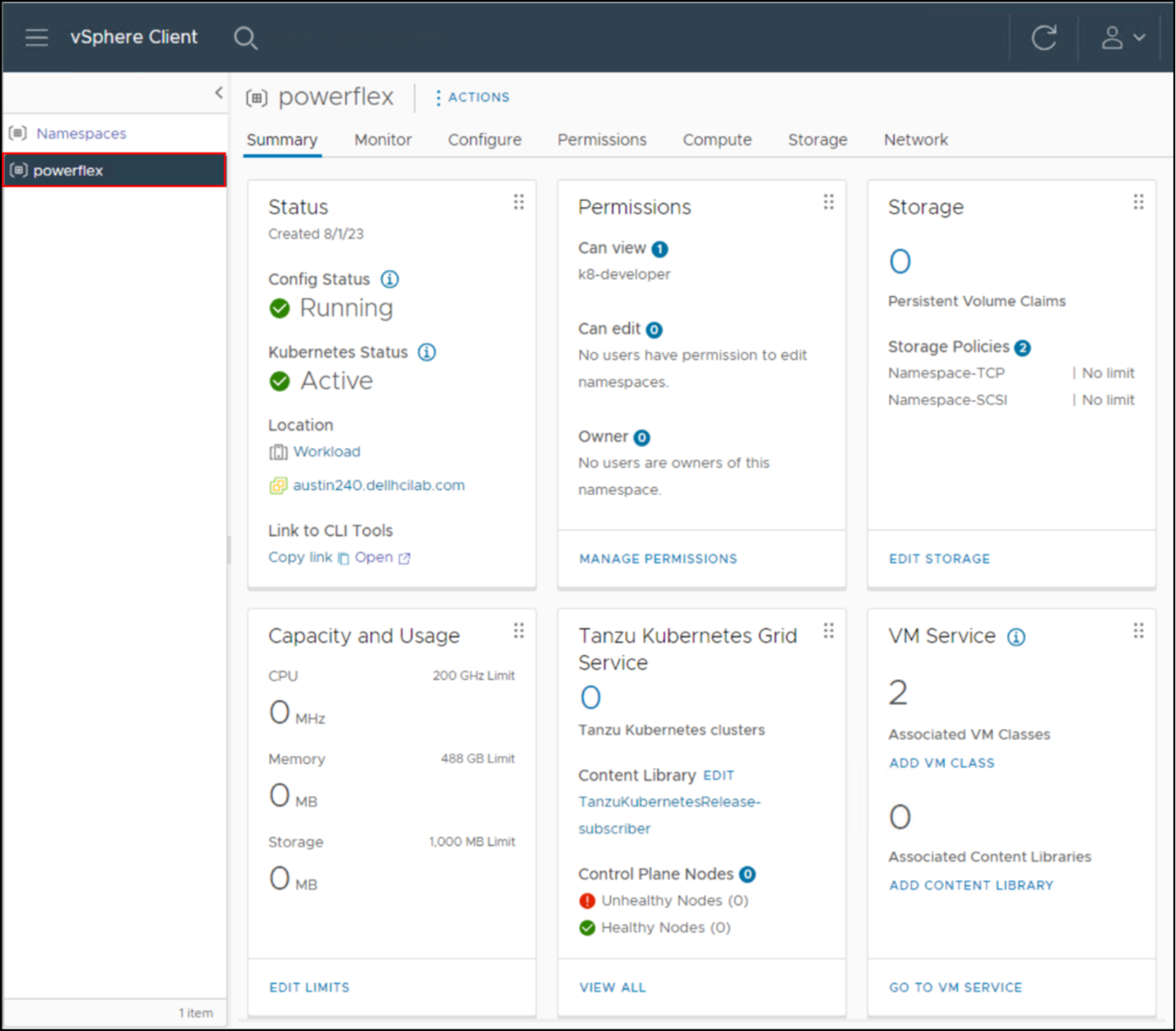
Figure 76. Completed PowerFlex namespace
- In vSphere, click the hamburger menu (