
OneFS architectural overview
OneFS architectural overview
-
OneFS collapses the traditional elements of the storage stack—data protection, volume manager, file system—into a single, unified software layer (see 0). This allows for a highly extensible file system that affords unparalleled levels of protection and availability.
Built atop FreeBSD’s UNIX implementation, availability and resilience are integral to OneFS from the lowest level on up. For example, unlike BSD, OneFS provides mirrored volumes for the root and /var file systems using the Mirrored Device Driver (IMDD), stored on flash drives. OneFS also automatically saves last known good boot partitions for further resilience.
On the network side, the logical network interface (LNI) framework provides a robust, dynamic abstraction for easily combining and managing differing interfaces, enabling network resilience. Multiple network interfaces can be trunked together with Link Aggregation Control Protocol (LACP) and Link Aggregation and Link Failover (LAGG) to provide bandwidth aggregation in addition to client session failover and general network resilience.
Within the cluster, every disk within each node is assigned both a Globally Unique Identifier (GUID) and logical drive number and is subdivided into 32 MB cylinder groups consisting of 8 KB blocks. Each cylinder group is responsible for tracking, using a bitmap, whether its blocks are used for data, inodes or other metadata constructs. The combination of node number, logical drive number, and block offset consist of a block or inode address and fall under the control of the aptly named Block Allocation Manager (BAM).
In addition to block and inode allocation, the BAM also handles file layout and locking and abstracts the details of OneFS distributed file system from the kernel and user space. The BAM never touches the disk itself, instead delegating tasks to the local and remote block manager elements respectively on the appropriate nodes. The Remote Block Manager (RBM) is essentially a Remote Procedure Call (RPC) protocol that uses either IP over Ethernet or the Socket Direct Protocol (SDP) over redundant Ethernet or InfiniBand for reliable, low-latency back-end cluster communication. These RBM messages—everything from cluster heartbeat pings to distributed locking control—are processed by a node’s Local Block Manager using the Device Worker Thread (DWT) framework code.
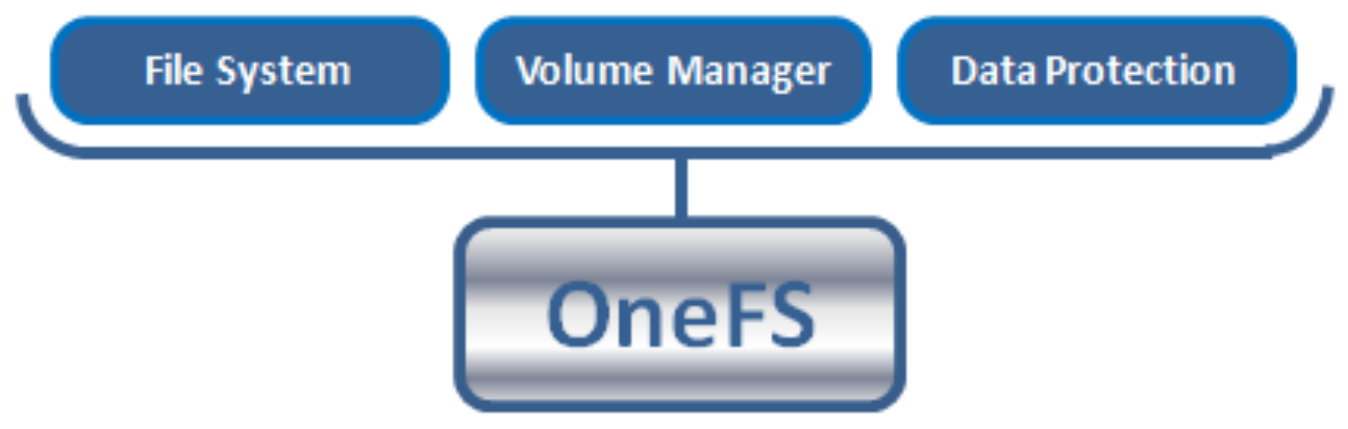
OneFS collapsed stack storage architecture
For more details about the OneFS architecture, see the PowerScale OneFS Technical Overview white paper.
Safe writes
For write operations, where coherency is vital, the BAM first sets up a transaction. Next it uses a 2-phase commit protocol (2PC) over the RBM to guarantee the success of an atomic write operation across all participant nodes. This is managed using the BAM Safe Write (BSW) code path. The 2PC atomically updates multiple disks across the 2PC participant nodes, using their journals for transaction logging. The write path operates as follows:
- Client performs a transactional write.
Block is written to journal; memory buffer is pinned.
Rollback data is maintained. - Transaction commits.
Journal data is pinned; memory buffer is dirty.
Rollback data can now be discarded.
Top-level operation is complete. - OneFS asynchronously flushes dirty buffers to disk at some point.
Placed into the writeback cache.
Journal data is still required, and memory buffer is discarded. - Journal approaches full or timeout and issues disk writeback cache flush.
This occurs relatively infrequently. - Cache flush complete.
Journal data is discarded for writes that were returned prior to flush.
Cluster group management
The OneFS Group Management Protocol (GMP) handles cluster coherence and quorum. The challenge is combining the various elements—performance, coherency, client access protocols—across multiple heads. The GMP is built on several distributed algorithms and strictly adheres to Brewer’s Theorem, which states that it is impossible for a distributed computer system to simultaneously guarantee consistency, availability, and partition tolerance. OneFS does not compromise on either consistency or availability.
Given this, a quorum group consisting of more than half of a cluster’s nodes must be active and responding at any given time. If a node is up and responsive but not a member of the quorum group, it is forced into a read-only state.
OneFS employs this notion of a quorum to prevent “split-brain” conditions that might possibly result from a temporary cluster division. The quorum also dictates the minimum number of nodes required to support a given data protection level. For example, seven or more nodes are needed for a cluster to support a +3n configuration. This allows for a simultaneous loss of three nodes while still maintaining a quorum of four nodes, allowing the cluster to remain operational.
The GMP tracks the state of all the nodes and drives that are considered part of the cluster. Whenever devices are added or removed from the cluster, either proactively or reactively, a group change is broadcast, the group ID is incremented, and any uncommitted journal write transactions are resolved.
For more information about cluster group management, see the PowerScale OneFS: Cluster Composition, Quorum, and Group State white paper.
Concurrency and locking
OneFS employs a distributed lock manager that uses a proprietary hashing algorithm to orchestrate coherent locking on data across all nodes in a storage cluster. The design is such that a lock coordinator invariably ends up on a different node than the initiator and either shared or exclusive locks are granted as required. The same distributed lock manager mechanism is used to orchestrate file system structure locks and protocol and advisory locks across the entire cluster. OneFS also supports delegated locks (SMB opportunistic locks and NFSv4 delegations) and also byte-range locks.
File layout
OneFS is a single file system providing one vast, scalable namespace—free from multiple volume concatenations or single points of failure. As such, all nodes access the same structures across the cluster using the same block addresses and all directories are inode number links emanating from the root inode.
The way data is laid out across the nodes and their respective disks in a cluster is fundamental to OneFS functionality. OneFS uses an 8 KB block size, and 16 blocks are combined to create a 128 KB stripe unit. Files are striped across nodes, allowing files to use the resources (spindles and cache) of up to 20 nodes, based on per-file policies.
The layout decisions are made by the BAM on the node that initiated a particular write operation using the 2PC described in Safe writes. The BAM Safe Write (BSW) code takes the cluster group information from GMP and the chosen protection policy for the file. It then uses that information to make an informed decision about where best to write the data blocks to ensure that the file is properly protected. The BSW generates a write plan, which consists of all the steps required to safely write the new data blocks across the protection group. Once the plan is complete, the BSW performs this write plan and guarantees its successful completion.
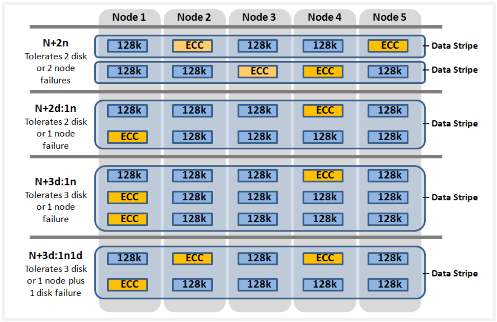
All files, inodes, and other metadata structures (B-trees) within OneFS are either mirrored up to eight times or erasure code protected, with the data spread across the various disk cylinder groups of multiple nodes. Erasure code protection uses an N+M scheme with N representing the number of nodes—the stripe width—and M the number of error correcting code (ECC) blocks. Flexible protection provides more details.
OneFS will not write files at less than the desired protection level. However, the BAM will attempt to use an equivalent mirrored layout if there is an insufficient stripe width to support a particular forward error correction (FEC) protection level.
Flexible protection
OneFS is designed to withstand multiple simultaneous component failures (currently four) while still affording unfettered access to the entire file system and dataset. Data protection is implemented at the file system level and, as such, is not dependent on any hardware RAID controllers. This provides many benefits, including the ability to add new data protection schemes as market conditions or hardware attributes and characteristics evolve. Since protection is applied at the file-level, a OneFS software upgrade is all that is required in order to make new protection and performance schemes available.
OneFS employs the popular Reed-Solomon erasure coding algorithm for its protection calculations. Protection is applied at the file-level, enabling the cluster to recover data quickly and efficiently. Inodes, directories, and other metadata are protected at the same or higher level as the data blocks they reference. Since all data, metadata and FEC blocks are striped across multiple nodes, there is no requirement for dedicated parity drives. This both guards against single points of failure and bottlenecks and allows file reconstruction to be a highly parallelized process. Today, OneFS provides +1n through +4n protection levels, providing protection against up to four simultaneous component failures respectively. A single failure can be as little as an individual disk or, at the other end of the spectrum, an entire node.
OneFS supports several protection schemes. These include the ubiquitous +2d:1n, which protects against two drive failures or one node failure.
Note: The best practice is to use the recommended protection level for a particular cluster configuration. This recommended level of protection is clearly marked as suggested in the OneFS WebUI storage pools configuration pages and is typically configured by default.
The hybrid protection schemes are particularly useful for PowerScale chassis-based nodes and other high-density node configurations, where the probability of multiple drives failing far surpasses that of an entire node failure. In the unlikely event that multiple devices have simultaneously failed, such that the file is “beyond its protection level,” OneFS will reprotect everything possible and report errors on the individual files affected to the cluster’s logs.
OneFS also provides various mirroring options ranging from 2x to 8x, allowing from two to eight mirrors of the specified content. Metadata, for example, is mirrored at one level above FEC by default. For example, if a file is protected at +1n, its associated metadata object will be 3x mirrored.
The following table summarizes the full range of OneFS protection levels:
Table 1. OneFS FEC protection levels
Protection level
Description
+1n
Tolerate failure of 1 drive OR 1 node
+2d:1n
Tolerate failure of 2 drives OR 1 node
+2n
Tolerate failure of 2 drives OR 2 nodes
+3d:1n
Tolerate failure of 3 drives OR 1 node
+3d:1n1d
Tolerate failure of 3 drives OR 1 node AND 1 drive
+3n
Tolerate failure of 3 drives or 3 nodes
+4d:1n
Tolerate failure of 4 drives or 1 node
+4d:2n
Tolerate failure of 4 drives or 2 nodes
+4n
Tolerate failure of 4 nodes
2x to 8x
Mirrored over 2 to 8 nodes, depending on configuration
OneFS hybrid protection schemes
Striped, distributed metadata coupled with continuous auto-balancing affords OneFS truly linear performance characteristics, regardless of fullness of file system. Both metadata and file data are spread across the entire cluster, keeping the cluster balanced at all times.
For more details about OneFS data protection levels, see the PowerScale OneFS Technical Overview white paper.
Failure domains and resource pools
Data tiering and management in OneFS are handled by SmartPools software. From a data protection point of view, SmartPools facilitates the subdivision of large numbers of high-capacity, homogeneous nodes into smaller, more Mean Time to Data Loss (MTTDL)-friendly disk pools. For example, an 80-node H500 cluster typically runs at +3d:1n1d protection level. However, partitioning it into four, 20-node pools would allow each pool to run at +2d:1n, thereby lowering the protection overhead and improving data utilization without any net increase in management overhead.
Automatic partitioning
In keeping with the goal of storage management simplicity, OneFS automatically calculates and partitions the cluster into pools of disks or “node pools,” which are optimized for both MTTDL and efficient space utilization. This means that protection-level decisions, such as with the preceding 80-node cluster example, are not left to the customer—unless the customer wants to make those decisions.
With automatic provisioning, every set of equivalent node hardware is automatically divided into node pools consisting of up to forty nodes and six drives per node. These node pools are protected by default at +2d:1n, and multiple pools can then be combined into logical tiers and managed using SmartPools file pool policies. By subdividing a node’s disks into multiple, separately protected pools, nodes are significantly more resilient to multiple disk failures than previously possible.
SmartPools automatic provisioning
For more information, see the Storage Tiering with Dell PowerScale SmartPools white paper.
The PowerScale modular hardware platforms such as the H700 feature a dense, modular design in which four nodes are contained in a single 4RU chassis. This approach enhances the concept of disk pools, node pools, and “neighborhoods,” which adds another level of resilience into the OneFS failure domain concept. Each PowerScale chassis contains four compute modules (one per node), and five drive containers, or sleds, per node.
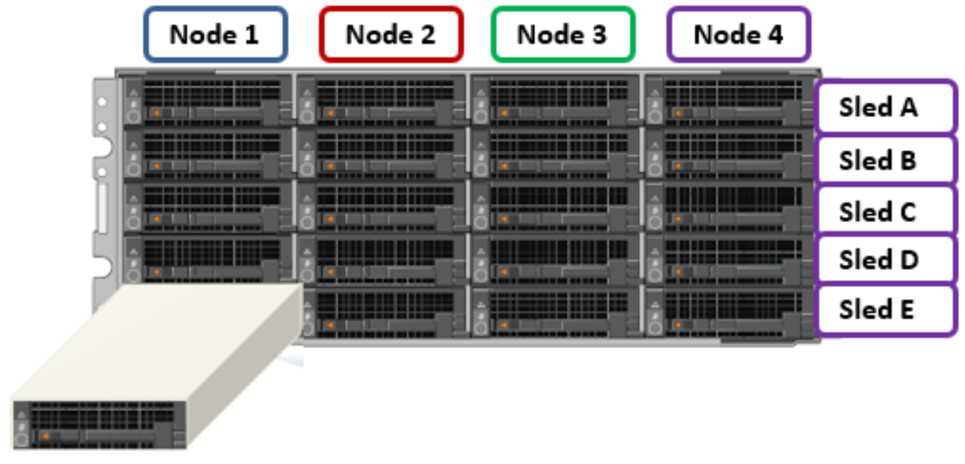
PowerScale chassis front view showing drive sleds
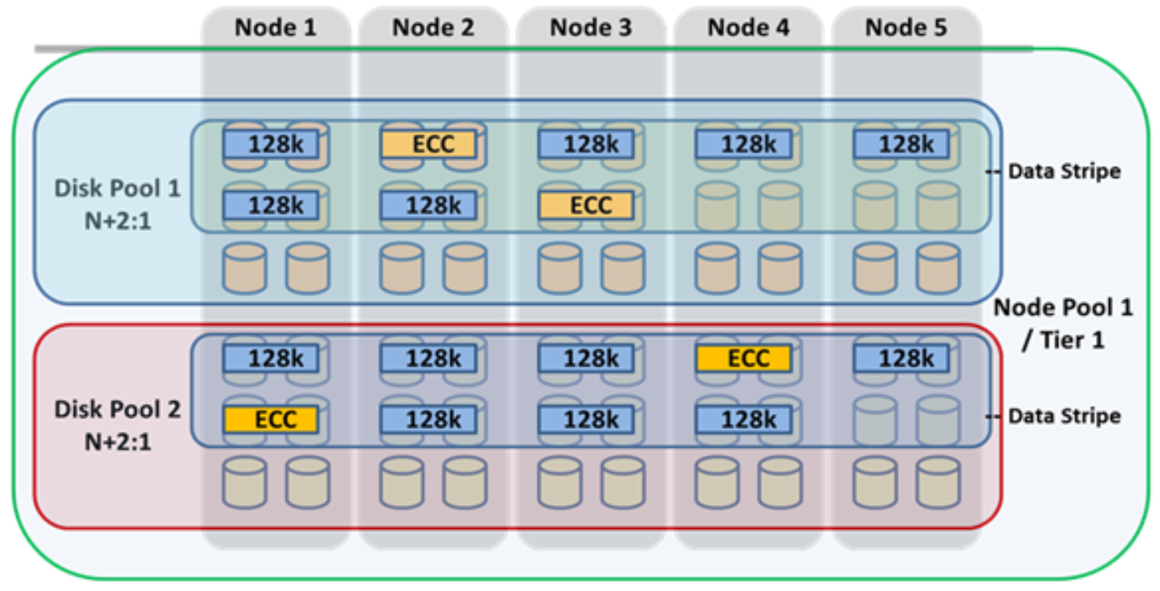
Each sled is a tray which slides into the front of the chassis and contains between three and six drives, depending on the configuration of a particular chassis. Disk Pools are the smallest unit within the Storage Pools hierarchy. OneFS provisioning works on the premise of dividing similar nodes’ drives into sets, or disk pools, with each pool representing a separate failure domain. These disk pools are protected by default at +2d:1n (or the ability to withstand two disks or one entire node failure).
Disk pools are laid out across all five sleds in each PowerScale chassis-based node. For example, a node with three drives per sled will have the following disk pool configuration:
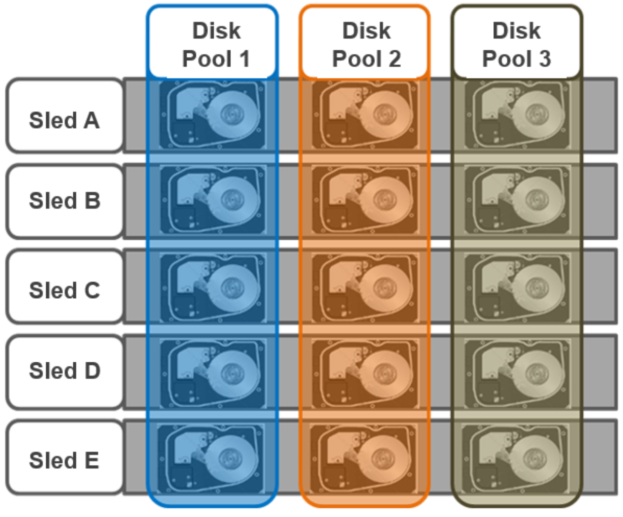
PowerScale chassis-based node disk pools
Node Pools are groups of Disk Pools, spread across similar storage nodes (compatibility classes). Multiple groups of different node types can work together in a single, heterogeneous cluster. For example: one Node Pool of F-Series nodes for IOPS-intensive applications, one Node Pool of H-Series nodes, primarily used for high-concurrent and sequential workloads, and one Node Pool of A-series nodes, primarily used for nearline or deep-archive workloads.
This allows OneFS to present a single storage resource pool consisting of multiple drive media types—SSD, high-speed SAS, large capacity SATA—providing a range of different performance, protection, and capacity characteristics. This heterogeneous storage pool in turn can support a diverse range of applications and workload requirements with a single, unified point of management. It also facilitates the mixing of older and newer hardware, allowing for simple investment protection even across product generations, and seamless hardware refreshes.
Each Node Pool contains only disk pools from the same type of storage nodes, and a disk pool may belong to exactly one node pool. For example, F-Series nodes with 1.6 TB SSD drives would be in one node pool, whereas A-Series nodes with 10 TB SATA drives would be in another. Today, a minimum of four nodes (one chassis) is required per node pool for chassis-based platforms, such as the PowerScale H700, or three nodes per pool for self-contained nodes such as the PowerScale F910.
OneFS “neighborhoods” are fault domains within a node pool, and their purpose is to improve reliability in general and guard against data unavailability from the accidental removal of drive sleds. For self-contained nodes such as the PowerScale F710, OneFS has an ideal size of 20 nodes per node pool and a maximum size of 39 nodes. On the addition of the 40th node, the nodes split into two neighborhoods of 20 nodes.
Neighborhood
F-series Nodes
H-series and A-series Nodes
Smallest Size
3
4
Ideal Size
20
10
Maximum Size
39
19
With the PowerScale chassis-based platforms, such as the H700 and A300, the ideal size of a neighborhood changes from 20 to 10 nodes. This protects against simultaneous node-pair journal failures and full chassis failures.
Partner nodes are nodes whose journals are mirrored. With the chassis-based platform, rather than each node storing its journal in NVRAM, the nodes’ journals are stored on SSDs, and every journal has a mirror copy on another node. The node that contains the mirrored journal is referred to as the partner node. A mirrored journal provides several reliability benefits. For example, SSDs are more persistent and reliable than NVRAM, which requires a charged battery to retain state. Also, with the mirrored journal, both journal drives have to die before a journal is considered lost. As such, unless both of the mirrored journal drives fail, both of the partner nodes can function as normal.
With partner node protection, where possible, nodes are placed in different neighborhoods—and hence different failure domains. Partner node protection is possible once the cluster reaches five full chassis (20 nodes), when, after the first neighborhood split, OneFS places partner nodes in different neighborhoods:
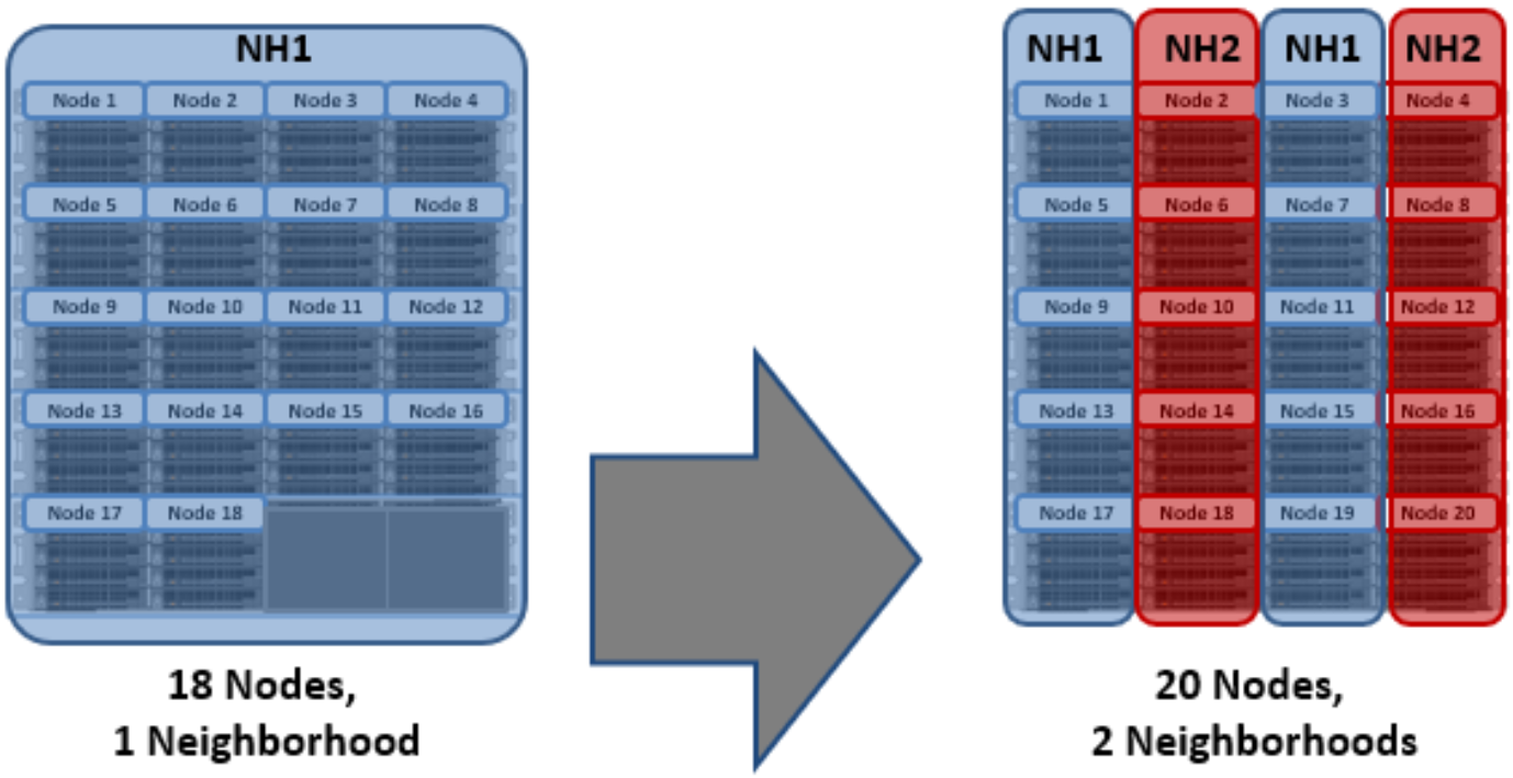
Split into two neighborhoods at 20 nodes
Partner node protection increases reliability. If both nodes go down, they are in different failure domains, so their failure domains only suffer the loss of a single node.
With chassis protection, when possible, each of the four nodes within a chassis is placed in a separate neighborhood. Chassis protection becomes possible at 40 nodes because the neighborhood split at 40 nodes enables every node in a chassis to be placed in a different neighborhood. As such, when a 38-node Gen6 cluster is expanded to 40 nodes, the two existing neighborhoods are split into four 10-node neighborhoods.
Chassis protection ensures that if an entire chassis was to fail, each failure domain would only lose one node.
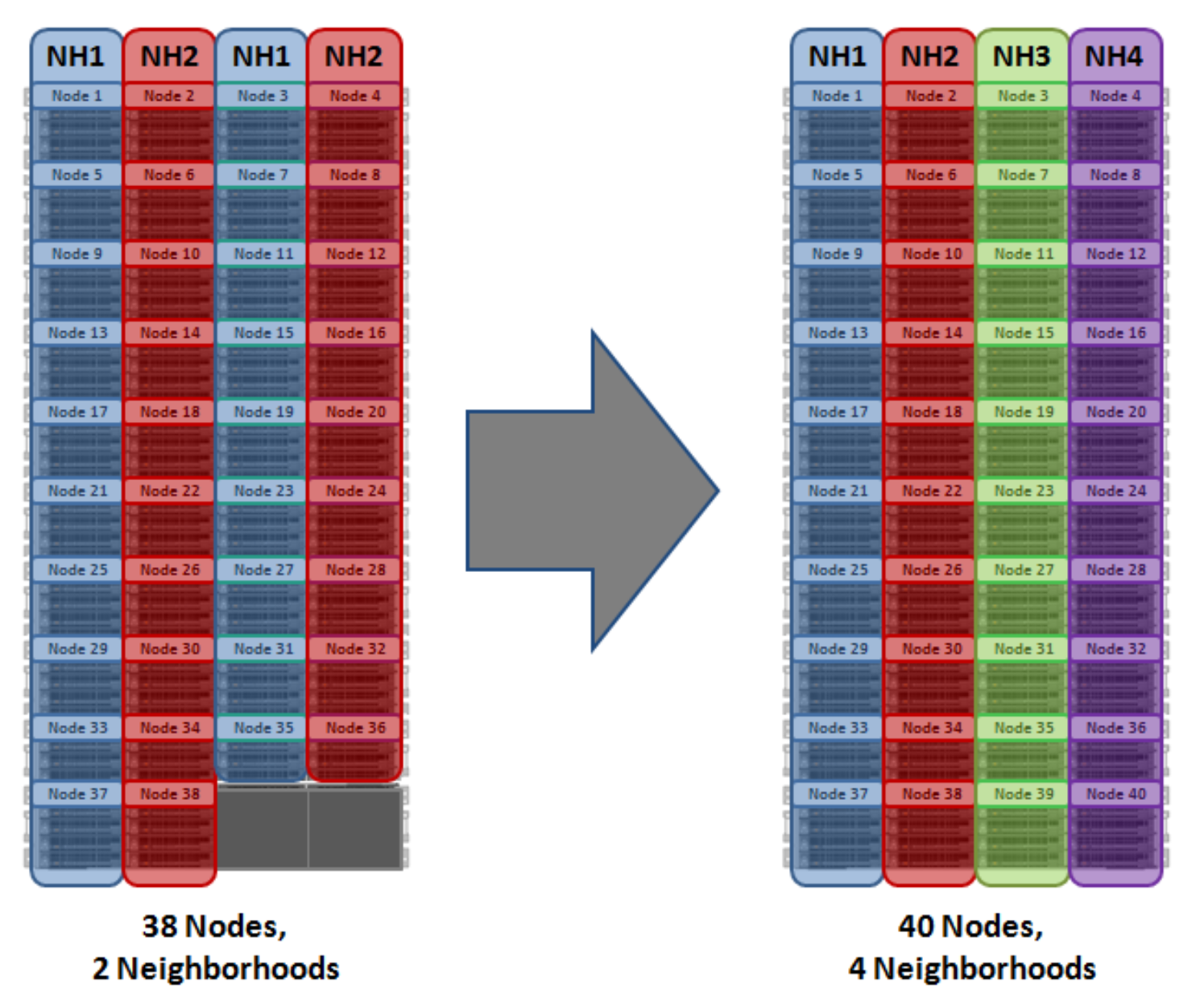
OneFS neighborhoods—four-neighborhood split
A 40-node or larger cluster with four neighborhoods and protected at the default level of +2d:1n can sustain a single node failure per neighborhood. This protects the cluster against a single full-chassis failure.
Overall, a cluster consisting of chassis-based nodes has reliability at least one order of magnitude greater than previous-generation clusters of a similar capacity as a direct result of the following enhancements:
- Mirrored journals
- Smaller neighborhoods
- Mirrored boot drives
Manual node pool management
Once a node pool has been automatically provisioned, additional manual node pools can be created. When complete, the constituent nodes can then be manually reassigned across these node pools, as wanted. Manual node pools require a minimum of three nodes in each pool (four for chassis-based hardware, such as the A300). They are considered an advanced cluster configuration because they can have a significant impact on cluster performance.
Virtual hot spares
SmartPools also provides a virtual hot spare option, if wanted. This functionality allows space to be reserved in a disk pool, equivalent to up to four full drives. This virtual hot spare pool can be immediately used for data reprotection in the event of a drive failure.
From a data availability and management point of view, SmartPools also applies storage tiering concepts to disk pools, allowing the storage and movement of data according to rich file policies or attributes. As such, SmartPools facilitates the automated alignment of data with the appropriate class of storage according to its business value, performance profile, and availability requirements. A cluster can thereby provide multiple storage pools, each supporting a range of availability SLAs within a single, highly scalable, and easily managed file system. This resource pool model aligns well with the current IT trend of private and hybrid cloud initiatives.
For more information, see the Storage Tiering with Dell PowerScale SmartPools white paper.
- Client performs a transactional write.