
None
None
-
This design uses the NVIDIA Spectrum-X networking platform, and consists of three physical networks:
- Frontend network for management, storage, and client/server traffic that is powered by two Spectrum-4 SN5400 switches
- Backend network for internode GPU communication using one or more Spectrum-4 SN5600 switches
- Out-of-band management traffic that is powered by the Spectrum SN2201 switch
The following figure shows the network topology used for the reference design:
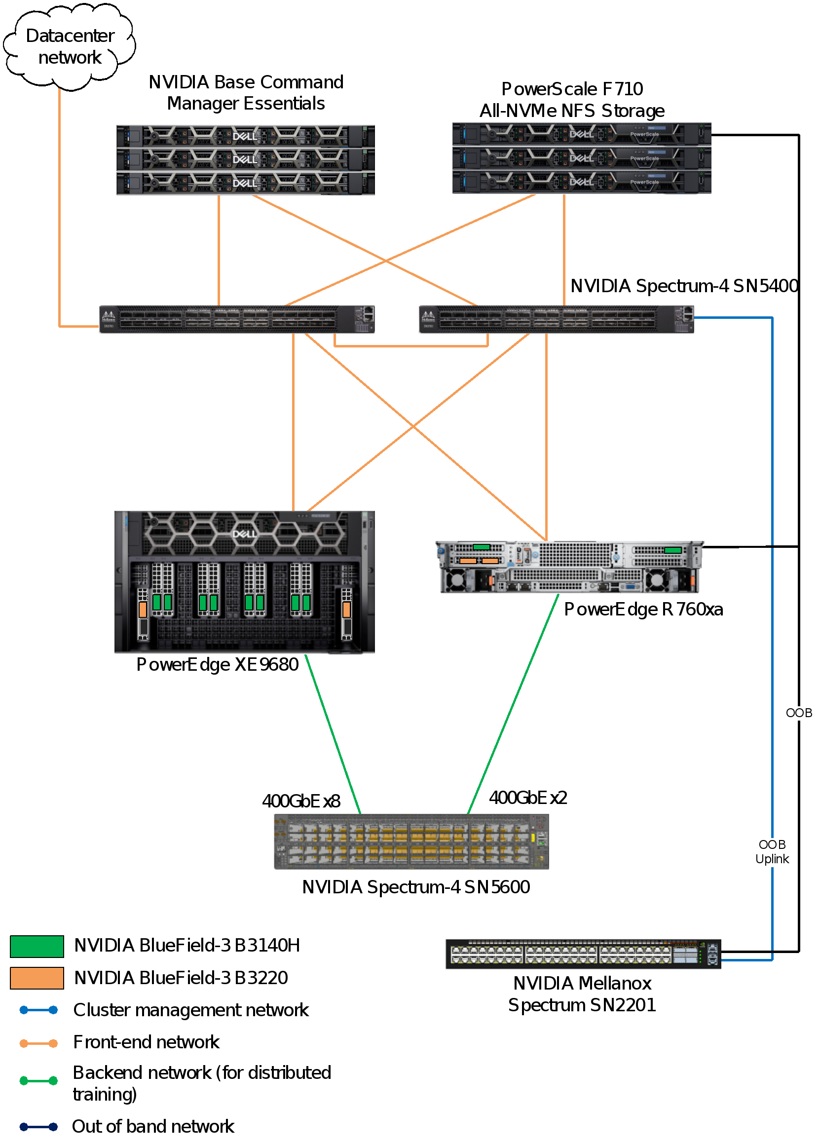
Figure 7. Network configuration for the reference design
Note: The figure shows only a single PowerEdge XE9680 server and a single PowerEdge R760xa server, which is for the purpose of illustration.
Cluster management and out-of-band network fabric
The cluster management and out-of-band (OOB) network is a separate and dedicated physical network infrastructure used for managing and monitoring the servers. Because of the low network requirements, a 1-Gigabit Ethernet network suffices.
There are two design options available for this setup:
- Converge both the OOB integrated Dell Remote Access Controller (iDRAC) and cluster management on a single 1 GbE. This task includes configuring the LAN on motherboard (LOM) to function as a shared LOM, with separate VLANs for cluster management and iDRAC OOB management.
- Use the iDRAC dedicated NIC on the PowerEdge XE9680 server and have an isolated network connection to the switch.
Backend (east-west/GPU) network fabric
The backend network fabric, also referred to as the GPU, Scale Out, or east-west network fabric, is a 400 Gb Ethernet high-bandwidth low latency network fabric dedicated for inter-node GPU fabric communication. It is required for distributed fine-tuning of LLMs to facilitate rapid communication between different nodes in a distributed computing environment. Backend network fabric is typically not required for inference-only clusters, in which the model fits inside a single server. This design uses the Llama 3 model, which fits in a single PowerEdge XE9680 or PowerEdge R760xa server for inferencing and a backend network fabric is not needed.
The backend network is powered by a Spectrum-4 SN5600 switch, which is a versatile network switch that serves as a smart-leaf, spine, and super-spine. It provides 64 ports of 800 GbE, all packed into a compact 2U form factor. This switch is suitable for an inter-GPU fabric. It supports both conventional leaf/spine designs with top-of-rack (ToR) switches and end-of-row (EoR) topologies. The SN5600 switch offers a wide range of connectivity options, from one to 800 GbE. It stands out in the industry with a leading total throughput of 51.2 Tb/s.
Spectrum-X incorporates the following capabilities to support innovations to achieve the highest effective bandwidth under load and at scale:
- NVIDIA RDMA over Converged Ethernet (RoCE) Adaptive Routing on Spectrum-X switches
- NVIDIA Direct Data Placement (DDP) on Spectrum-X SuperNIC
- NVIDIA RoCE Congestion Control on both Spectrum-X switches and SuperNICs
- NVIDIA AI Acceleration Software
- End-to-end AI network visibility using NVIDIA NetQ
The following figure shows the front view of the PowerEdge XE9680 chassis:
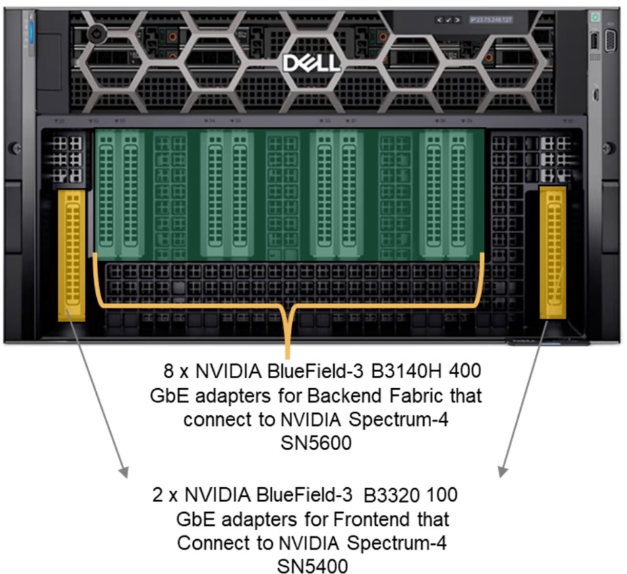
Figure 8. Front chassis view of the Dell PowerEdge XE9680 server
There are 10 PCIe Gen 5 slots on the PowerEdge XE9680 server, which are internally connected to the CPU and GPU using PCIe switches. Each of the 10 PCIe slots is configured with eight NVIDIA Bluefield-3 Single Port 400 GbE B3140H adapters that are connected to a Spectrum-4 5600 switch, which constitutes the backend fabric.
Frontend (north-south) network fabric
The frontend network fabric in this design refers to the standard Data Center Fabric providing connectivity to resources outside the AI cluster. As shown in Figure 1, it is a converged fabric that supports storage, external data center access, and Kubernetes management operations. This network fabric is often referred to as the north-south network.
A pair of Spectrum-4 SN5400 switches power the frontend network fabric. These switches connect to the PowerScale F710 storage arrays and the PowerEdge R660 Kubernetes and Base Command Manager. Also, the switches provide external access by connecting to the data center network. They also connect to the PowerEdge XE9680 or PowerEdge R70xa server node using NVIDIA Bluefield-3 Dual Port 200 GbE.
Cables and optics
NVIDIA’s Ethernet Switch Configurator can be used to help identify and order the appropriate cables and optics for your AI fabrics. After entering your topology information into the form, it lists the available product options for your environment, along with part numbers and other information.
For the network design that is shown in Figure 7, customers can either use Direct Attached Copper (DAC) or fiber.
- For the backend network:
- DAC option: 800 Gb/s Twin-port OSFP to 2x 400G QSFP cables are required. The 800 Gb OSFP connects to the Spectrum-X SN5600 switch while the 400G QSFP112 connects to BlueField-3 B3140H. See an example DAC Splitter cable product specification for more information.
- Fiber option: NVIDIA 800 Gb/s OSFP twin port transceiver can be used on the switch side, NVIDIA 400Gbps QSFP112 single port transceiver on the BlueField-3 B3140H and NVIDIA passive fiber cable (MPO12 APC to MPO12) can be used to connect them
- For the frontend network:
- DAC option: 400 Gbs QSFP-DD to QSFP112 cables are required. The 400G QSFP-DD connects to Spectrum-X SN5400, while the QSFP112 connects to BlueField-3 B3220. For more information, see the list of supported transceivers and cables.
- Fiber option: NVIDIA 400Gbps QSFP-DD transceiver can be used on the switch side and 400Gbps QSFP112 transceiver on the BlueField-3 B3220. NVIDIA passive fiber cable, MMF, MPO12 APC to 2xMPO12 APC can be used to connect them.
Building a PowerEdge XE9680 GPU cluster with Spectrum-X
Each GPU in the Dell PowerEdge XE9680 server is coupled through PCIe with a respective NIC that interfaces with the fabric at 400 GbE speed, as shown in the following figure. Different types of cabling are supported; direct attach copper (DACs) or fiber.
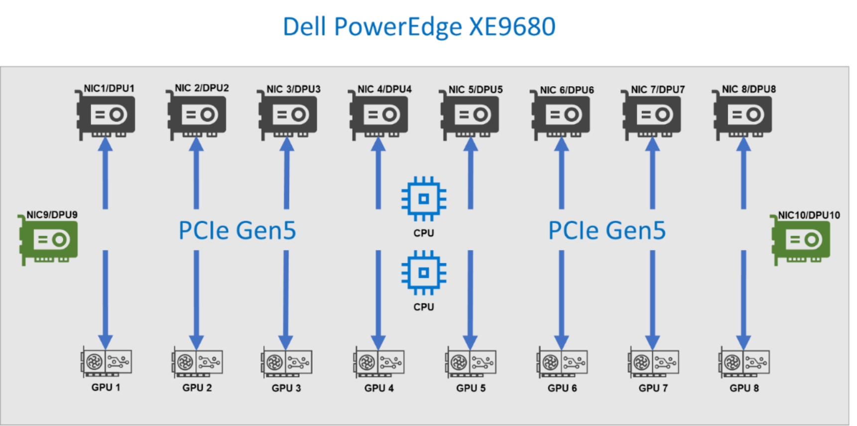
Figure 9. Components of a Dell PowerEdge XE9680 server
The following figure shows the front view of the PowerEdge XE9680 server:
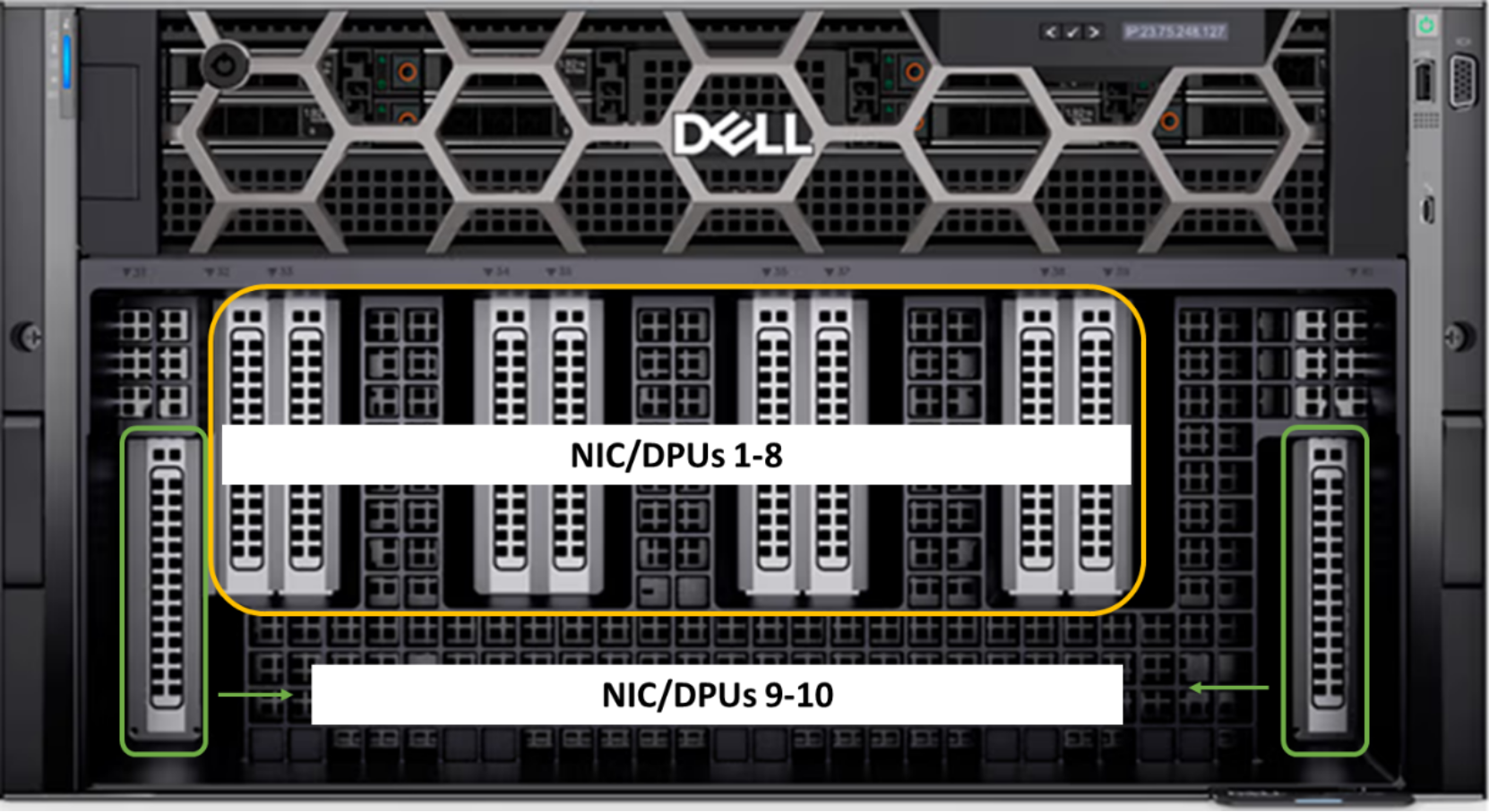
Figure 10. Dell PowerEdge XE9680 server front view
The NICs in the two PCIe slots on the far right and far left are used for the frontend fabric connections. The eight GPU NICs are coupled with the eight GPUs and used to connect to the Scale Out Fabric.
Scale Out fabric
The following figure shows that the Scale Out fabric interconnects the NICs coupled with the GPUs in a PowerEdge XE9680 server to build a GPU cluster including more than a single node. The Scale Out fabric is used by the set of GPUs composing a GPU cluster to exchange AI workload parameters.
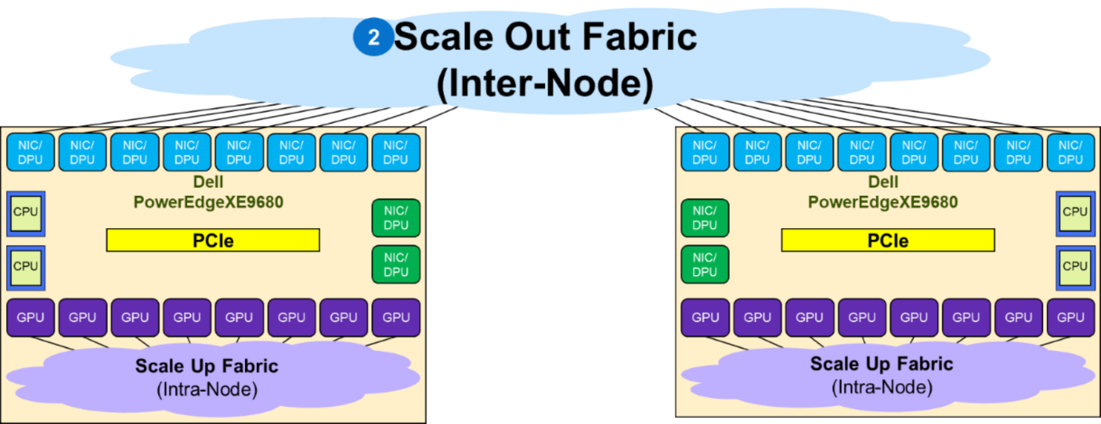
Figure 11. Scale Out fabric
When deploying a Scale Out fabric, keep the following guidelines in mind:
- There is no EVPN VXLAN BGP deployed as the networking protocol because multitenancy GPU service is not a requirement. It is best to deploy plain BGP as the network protocol in the fabric.
- Switch redundancy, that is, MC-LAG is not needed. Link redundancy is achieved by multiple active links between leaf and spine, as well as GPU connections to multiple leaf switches.
This list is not an exhaustive networking design checklist as the fabric configuration requires detailed planning and design throughout the entire deployment cycle.
Multiple topologies can be used to build a Scale Out Fabric:
- Single Switch topology
- TOR-Wired Clos topology
- Pure Rail topology
- Rail Optimized topology
Single switch topology
The Scale Out Fabric topology is a single switch topology, which is the simplest instance of a TOR-Wired Clos topology. The following figure shows the connectivity properties of the TOR-Wired Clos topology:
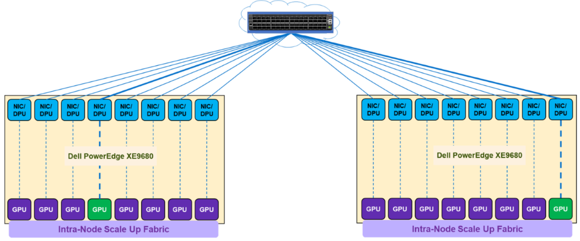
Figure 12. Single switch topology
This topology enables direct Scale Out Fabric communication between any GPU pairs without involving the Scale Up Fabric. For example, GPU 4 on server 1 can directly communicate through NIC 4 on server 1 with GPU 8 on server 2, because the single switch topology (or TOR-Wired Clos topology) enables NIC 4 on server 1 to communicate with NIC 8 on server 2 and NIC 8 on server 2 is coupled with GPU 8 on server 2.
The following items characterize a single switch topology:
- Single NVIDIA Spectrum-X switch
- 1 to 16 (or 1 to 8) Dell PowerEdge XE9680 servers
- 8 to 128 (or 8 to 64) GPU cluster
- Layer 2 or Layer 3 with RoCEv2
The following figure shows a single switch fabric using the NVIDIA SN5600 switch:
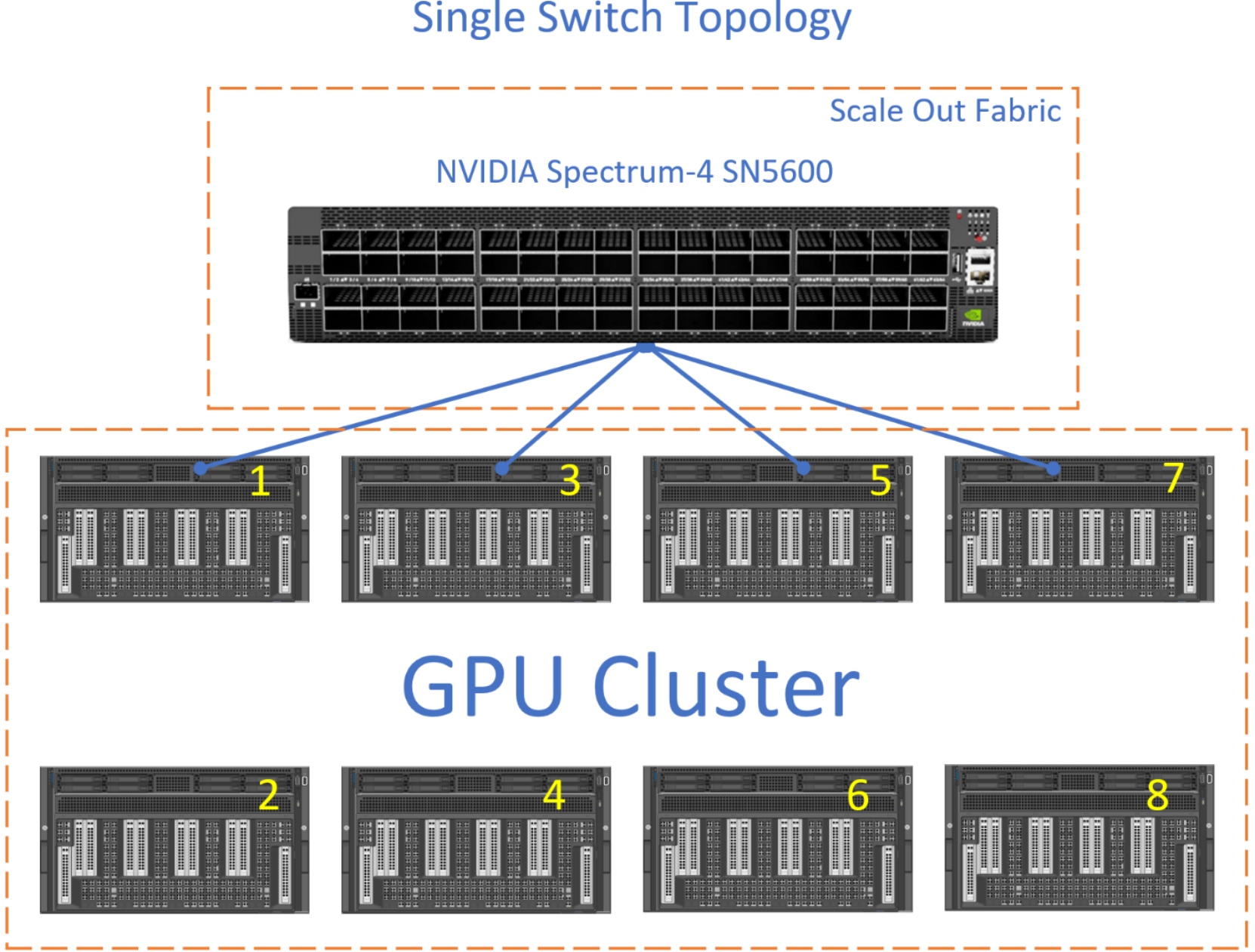
Figure 13. Single switch topology
The connections from each GPU to the switch can be 800 GbE or 400 GbE.
Rail Optimized topology
In this topology, each NIC is connected to a different switch (or spine-leaf network) and is called a rail. The rails are also interconnected at an upper tier. Therefore, this topology provides two ways to cross rails: through the Scale Up fabric (preferred) or through the upper tier of the Scale Out topology.The following figure shows the connectivity properties of the Rail Optimized topology:
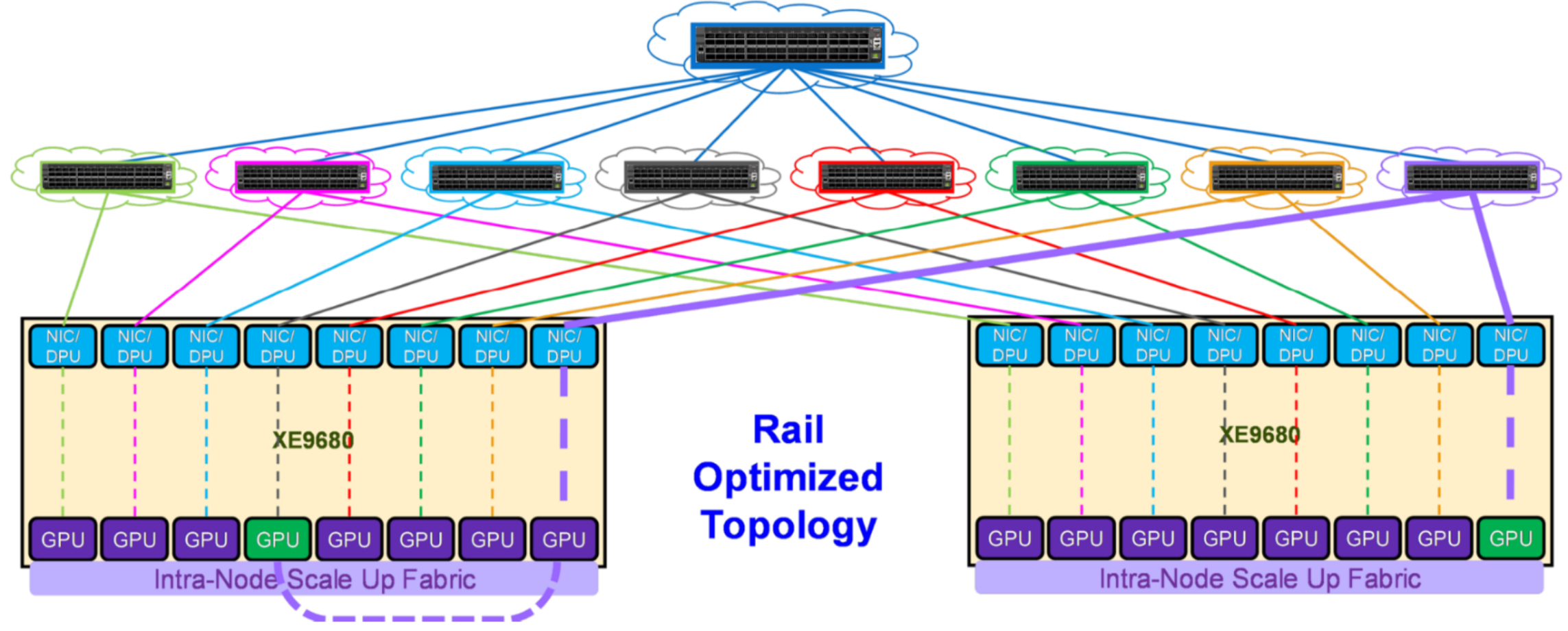
Figure 14. Rail Optimized topology
For example, to communicate with GPU 8 on server 2, GPU 4 on server 1 can either:
- Transfer its data into the memory of GPU 8 on server 1. Then GPU 8 on server 1 communicates through NIC 8 on server 1 with GPU 8 on server 2, through NIC 8 on server 2. This path is shown with purple lines in Figure 14.
- Send its data to NIC 4 on server 1, which can reach through the upper tier to NIC 8 on server 2, coupled with GPU 8 on server 2.
This property allows AI workloads to perform better on a Rail Optimized topology than on a Pure Rail topology because the current Collective Communication Libraries are not yet fully optimized for the Pure Rail topology. As such, the Rail Optimized topology is the recommended topology to build a Scale Out fabric (see Trade-offs).
The following figure shows an example of Rail Optimized topology with the NVIDIA SN5600 switch:
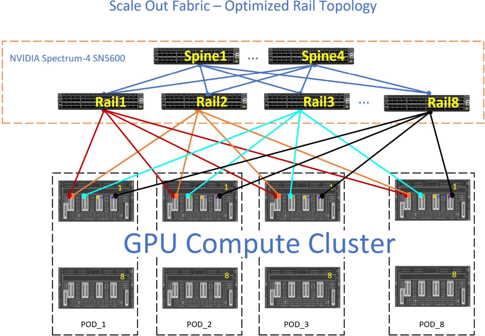
Figure 15. Scale Out fabric - Rail Optimized topology example
The Rail Optimized topology provides the same set of benefits as a Pure Rail topology, plus scalability and connectivity through the upper tier. There are times when the GPU-to-GPU across different nodes might not take the optimum path and the upper tier have to provide connectivity between the different rails.
For example, the red GPU on NODE_1, POD_1 wishes to communicate with the green GPU on NODE_1, POD_3. Ideally, the data path is for the red GPU to use the internal fabric on NODE_1 to communicate with the green GPU on NODE_1, and then the green GPU on NODE_1 transmits this data to Rail3. However, if this data path is not available, then the red GPU transmits its data upstream towards Spine1, where Spine1 sends this data downstream to Rail3.
Trade-offs
The TOR-wired Clos topology allows shorter cables to connect servers to leaf switches in a rack, enabling cheaper DAC cables in place of optical cables.
Conversely, the Pure Rail and Rail Optimized topologies provide better GPU reachability (that is, more GPUs at one-hop distance). Therefore, these topologies allow better performances for AI workloads, which is why they are recommended over the TOR-wired Clos topology.