
Installation and configuration steps
Installation and configuration steps
-
LoadMaster-terminated SSL communication
The simplest and most common use is for the client to the Kemp LoadMaster traffic to be encrypted and LoadMaster to ECS is not. In this scenario, the LoadMaster offloads the CPU-intensive SSL processing from ECS.
Here is a general overview of the steps we will walk through in this example:
- Step 1: Import a certificate to the LoadMaster.
- Step 2: Create a virtual server for LoadMaster terminated SSL connectivity to a single ECS cluster
- Step 3: Test connectivity to ECS
Step 1: Import the certificate into the LoadMaster
- Import the Self-signed certificate to the LoadMaster. The certificate and private key are required for import.
- On the LoadMaster, navigate to Certificates & Security/ SSL Certificates and select SSL Certificates.
- Click Import Certificate.
- Provide the following:
- Select Browse for Certificate File and select the trusted CA or self-signed certificate.
- Select Browse for Key File and select the .key file.
- Under Certificate Identifier, provide a name for the certificate.
- Click Save.
- Click OK.
Step 2: Create a virtual server for LoadMaster terminated SSL connectivity to a single ECS cluster
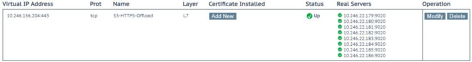
Create a new Virtual Server to publish ECS on port 443. This configuration will provide encryption to the LoadMaster. The LoadMaster will forward the traffic to ECS un-encrypted using the S3 protocol and port 9020.
- Within the LoadMaster Web User Interface (WUI), navigate to Virtual Services/ Add New.
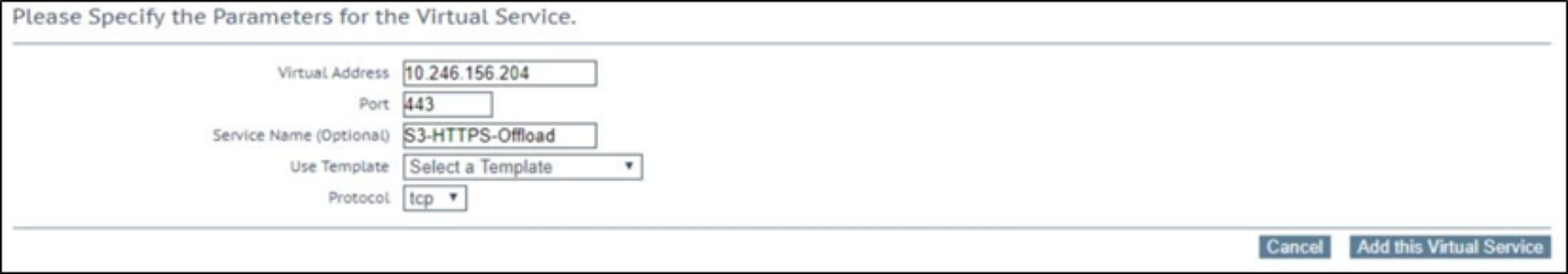
- Enter the details in the required fields:
- IP address for the Virtual Service
- Virtual Service Port number (443)
- Friendly name for the Virtual Service (that is S3-HTTPS-Offload)
- Select TCP as the protocol
- Click Add this Virtual Service.
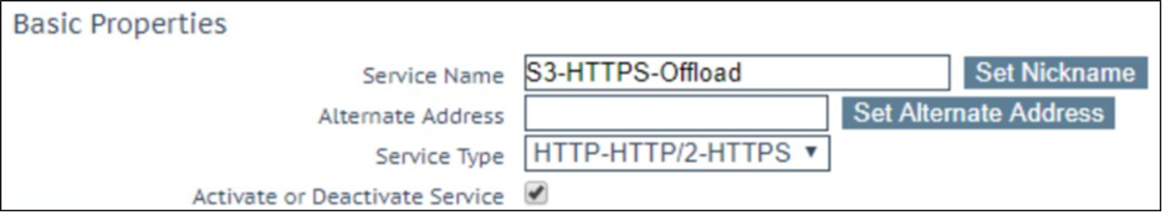
- Under Basic Properties, ensure that Service Type is HTTP-HTTP/2-HTTPS.
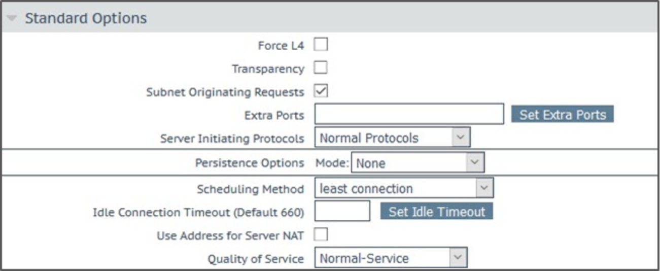
- Expand Standard Options.
- If LoadMaster is configured with multiple interfaces, be sure to enable Subnet Originating Requests.
- Select the appropriate Scheduling Method.
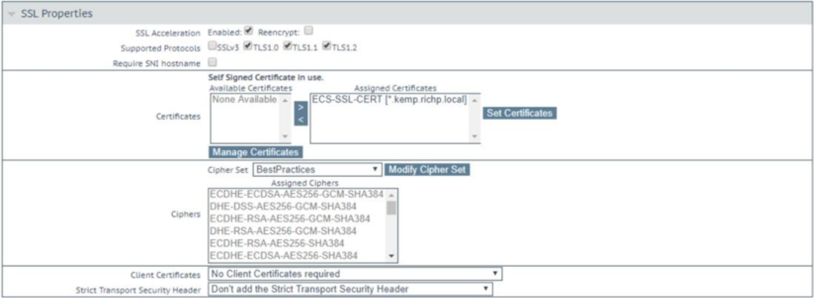
- Expand SSL Properties and select the Enabled for SSL Acceleration check box.
- Under SSL Properties, configure the following:
- Clear the Reencrypt check box.
- Select the check boxes for TLS1.0, TLS 1.1, and TLS 1.2.
- Select the certificate that was imported earlier and click the arrow to move it to Assigned Certificates.
- Click Set Certificates.
- Select BestPractices as the cipher set.
- Expand Real Servers.
Using the S3 Ping operation is recommended in monitoring ECS S3 service port availability on ECS software running on dedicated ECS hardware. To configure S3 Ping as the Real Server Check Method on the LoadMaster, see the section
Global Limits
Global Limits apply QoS to all requests
- Maximum Concurrent Connections: Limits the maximum number of simultaneous connections allowed to ECS Connection Manager.
- Global Connections Limit: Limits the maximum number of connection attempts per second (CPS).
- Global HTTP Requests Limit: Limits the maximum number of HTTP request attempts per second (RPS).
- Global Bandwidth Limit: Limits the maximum bandwidth for ECS Connection Manager.
Limiter Options
Limiter Options controls the behavior of QoS
- Error Response: By default, ECS Connection Manager drops any connections when the limit is reached. A more graceful response (429 - Too Many Connections or 503 - Service Unavailable) can be sent back to the client or application requesting access.
- Fail on RS / Sub-VS Rate Limiting: If rate limiting is activated for a Real Server (RS) or SubVS, ECS Connection Manager tries to select a different RS/SubVS to use for the connections. Enabling this will force the request to fail with the selected Error Response selected.
- Generate Limiter Statistics: Generates a global summary syslog message every five seconds that contains the state of the limiting subsystem.
- Client Message Repeat Delay: Sets the minimum time after a client is no longer limited before a new message is generated.
Client Limiting
- Maximum Client Concurrent Limit: Limits the maximum number of simultaneous connections allowed by a single client or application. A default (global) setting must be set before applying limits based on specific IP addresses or networks.
- Client Connections/sec Limit: Limits the maximum number of connections per second (CPS) allowed by a single client or application. A default (global) setting must be set before applying limits based on specific IP addresses or networks.
- Client Requests/sec Limit: Limits the maximum number of requests per second (RPS) allowed by a single client or application. A default (global) setting must be set before applying limits based on specific IP addresses or networks.
- Client Bandwidth Limit: Limits the maximum bandwidth allowed by a single client or application. A default (global) setting must be set before applying limits based on specific IP addresses or networks.
URL Based Limiting
- Request URL: Limits the number of attempts based on the request URL (ECS Bucket Name)
- Host: Limits the number of attempts based on the domain name of the request (ECS Namespace)
- User Agent: Limits the number of attempts based on the User Agent of the request (Operating System, software vendor, or software version).
- Method: Limits the number of attempts based on the HTTP request method. (GET, PUT, DELETE)
Per-Virtual Service Limiting
- Connections per second: Limits the maximum number of connections per second (CPS) allowed for a Virtual Service of Sub Virtual Service.
- HTTP Requests per second: Limits the maximum number of requests per second (RPS) allowed for a Virtual Service of Sub Virtual Service.
- Concurrent Connections: Limits the maximum concurrent connections allowed for a Virtual Service of Sub Virtual Service.
- Bandwidth Limit (Kilobits/sec): Limits the maximum bandwidth allowed for a Virtual Service of Sub Virtual Service.
GSLB Clustering
To add the ECS nodes as Real Servers, click Add New.
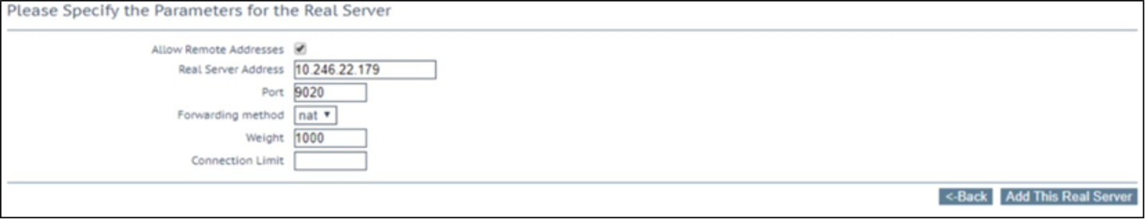
- Enter the details in the required fields.
- For Real Server Address, enter the IP Address of the ECS Node.
- Enter Port 9020.
- Forwarding method NAT.
- Leave the default Weight of 1000.
- Click Add This Real Server.
- Continue to add each additional ECS node in the cluster to Real Servers.
- Navigate to Virtual Services/ View Modify Services to confirm the health of the Virtual Service.
Step 3: Test connectivity to ECS
S3 Browser is a freeware Windows client for Amazon S3 which can be used to connect to ECS.
- To add a new HTTPS account, select Add new account from the Accounts menu item. Provide an account name to identify the connection, select S3 Compatible Storage, enter a REST endpoint that points to the LoadMaster. ECS supports both V2 and V4 Signatures. Lastly, enter your ECS Object User ID and S3 password, and ensure that Use secure transfer (SSL/TLS) is selected.
- Create a bucket. Specify the bucket name and click Create new bucket.
- Verify that the bucket has been successfully created.
As with the virtual servers created for S3 application traffic, virtual servers can be created for Atmos and Swift protocols using the appropriate ports.
Global service load balancing with fixed weighting
Fixed weighted scheduling is usually used in Disaster Recovery (DR) sites. The highest weight Real Server is only used when other Real Server(s) are given lower weight values. However, if the highest weighted server fails, the Real Server with the next highest priority number is available to serve clients. The weight for each Real Server should be assigned based on the priority among the remaining Real Servers. When the failed Real Server becomes available, it automatically starts receiving requests.
This section describes how to configure Global Server Load Balancing for the ECS Virtual Services on the LoadMaster. Here is a general overview of the steps we will walk through in this example:
- Step 1: Configure Remote GEO LoadMaster Access
- Step 2: Set up GEO Clusters
- Step 3: Create a Global Balancing Fully Qualified Domain Name
- Step 4: Configure Source of Authority (SOA) and Resource Check Parameters
- Step 5: Configure DNS Delegation
Step 1: Configure Remote GEO LoadMaster Access
GEO settings can be synchronized between LoadMasters to simplify the configuration. Perform the following steps on each of the LoadMasters in the GSLB configuration. Open the LoadMaster WUI:
- In the main menu, select Certificates & Security and Remote Access.
- Under GEO Settings complete the following fields:
- For Remote GEO LoadMaster Access, type the IP address of all remote LoadMasters and the local LoadMaster that are included in this GLSB configuration and click Set GEO LoadMaster Access.
- For GEO LoadMaster Partners, type the IP address of just the remote LoadMasters in the GSLB configuration and click Set GEO LoadMaster Partners.
- For GEO LoadMaster Port, keep the default port (22).
- Ensure the correct GEO Update Interface is selected.
Repeat these steps on the additional LoadMasters. When all LoadMasters are configured with the remote IP address set, the Partner Status should show Green.
Step 2: Set up GEO Clusters
GEO Clusters can be configured to allow for the monitoring of Virtual Services as Layer 7. Each LoadMaster in the GLSB configuration must be added to the Cluster. You can perform these steps on one of the LoadMasters in the GSLB configuration, and you can replicate them to the others.
- In the main menu, select Global Balancing.
- Select Manage Clusters.
- Type the IP address of one of the LoadMasters in the GLSB configuration and give it a friendly name.
- Click Add Cluster.
- Click Modify.
- Change Type to Remote LM.
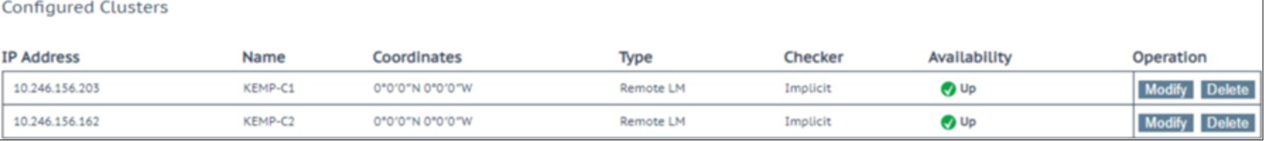
- Repeat these steps on the additional LoadMasters. Once complete, all LoadMasters will show Availability as Up.
Step 3: Create a Global Balancing Fully Qualified Domain Name
To configure Global Balancing on the Kemp LoadMaster, perform the following steps in the LoadMaster WUI. These steps can be done on one of the LoadMasters in the GSLB configuration and will be replicated to the others.
- In the main menu, select Global Balancing.
- Select Manage FQDN.
- Type the Fully Qualified Domain Name (FQDN) of the workload and click Add FQDN.
- Select the preferred Selection Criteria. This is going to be set based on requirements: some configurations may require Location Based/ Proximity or Round Robin while others can use Fixed Weighting for active/passive configurations.
- Enter the Virtual Service IP address for the LoadMaster and select the cluster with which this IP address is associated.
- Click Add Address.

- Set Checker to Cluster Checks and select the configured Virtual Service to monitor under Mapping Menu.
- Enter the IP address for the Virtual Service on the other LoadMaster and select the associated Cluster.
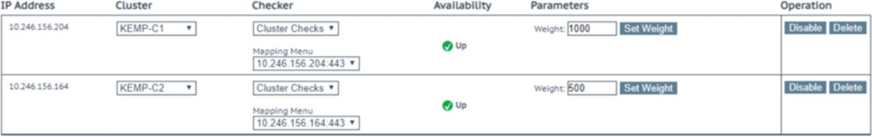
- Enter the Virtual Service IP address for the LoadMaster and Select the cluster with which this IP address is associated.
Repeat these steps for any additional LoadMasters in the GSLB configuration.
Step 4: Configure Source of Authority (SOA) and Resource Check Parameters
Because the LoadMasters in this configuration are responsible for resolving the FQDN, the SOA parameters should be complete:
- In the main menu, select Global Balancing.
- Select Miscellaneous Params.
- Configure the following settings:
Field
Example
Description
Zone Name
example.com
The name of the zone when using DNSSEC. This should be left blank if not using DNSSEC.
Source of Authority
kemp-ecs.example.com
The name of the domain owner.
Name Server
GEO1.example.com
The name of the DNS server.
SOA Email
DNS-Admin@example.com
Email address of the DNS administrator (who to contact if there is any issue with the DNS authoritative record).
TTL
1
(Time to Live), which is measured in seconds, defines how long a DNS answer is valid for.
- Enter the following settings for Resource Check Parameters:
Check Interval = 9
Connection Timeout = 4
Retry attempts = 2
- Enter the following setting for Stickiness:
Stickiness = 0
Step 5: Configure DNS Delegation
After the LoadMaster configuration is complete, delegation of DNS must be performed. This differs depending on the DNS provider.
- Create an entry (sometimes called a node) under the parent zone.
- The node must have both LoadMasters configured as name servers.
NFS using the LoadMaster
It is not recommended to balance NFS traffic load across ECS nodes without using persistence. This is because ECS nodes locally cache specific metadata attributes that NFS clients often query and read ahead (prefetch) NFS file data. These caching mechanisms allow fewer trips to disk, which reduces system response time and generally improves sequential read throughput. Load balancing each client's NFS traffic severely reduces the benefits of these ECS cache mechanisms.
A client application should be tied to a single ECS node during the session. Only during a failure should the connection between client and ECS be moved to another ECS node.
When using LoadMaster to publish NFS traffic, four Virtual Services are required. LoadMaster has a feature known as Port Following which does support the NFS persistence requirements. The following TCP and UDP ports must be configured for NFS traffic:
portmap
111
mountd, nfsd
2049
lockd
10000
This section will walk through the configuration of NFS Virtual Services on the LoadMaster. Here is a general overview of the steps we will walk through in this example:
- Step 1: Create and configure Virtual Service for TCP (111,2049,10000)
- Step 2: Create and configure Virtual Service for UDP 111
- Step 3: Create and configure Virtual Service for UDP 2049
- Step 4: Create and configure Virtual Service for UDP 10000
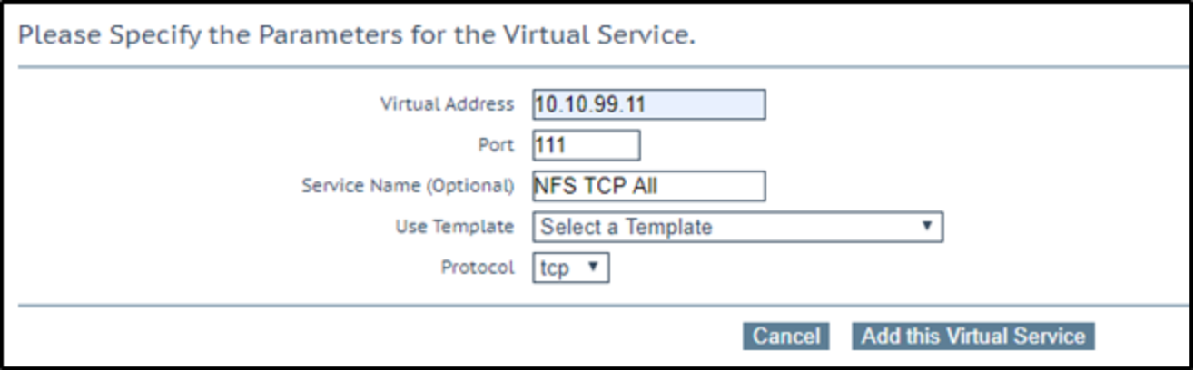
Step 1: Create and configure Virtual Service for TCP (111,2049,10000)
TCP Virtual Services allow for “Extra Ports” to be defined therefore all NFS TCP ports can be configured on one Virtual Service.
- In the main menu, select Virtual Services/ Add New.
- Enter the Virtual IP Address (VIP).
- Enter port 111.
- Provide a name for the Virtual Service.
- Ensure TCP is selected for protocol.
- Click Add this Virtual Service.
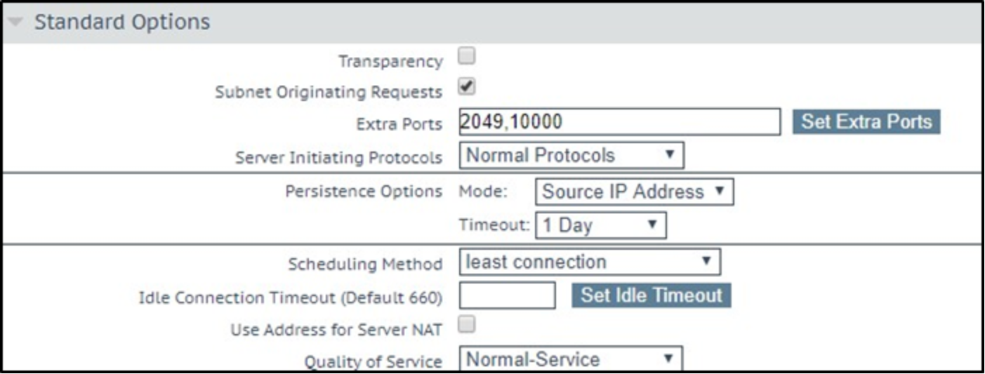
- Expand Standard Options and enter the following:
- Under Extra Ports enter 2049,10000 and click Set Extra Ports.
- Under Persistence Options enter Source IP Address.
- Change the Persistence Timeout to 1 Day.
- Change Scheduling Method to least connection.
- Expand Real Servers and enter the following:
- Set Checked Port to 111 and click Set Check Port.
- Click Add New …
- Enter the IP address of an ECS Node.
- Ensure that Port 111 is entered and click Add This Real Server.
- Repeat these steps for all additional ECS Node IP Addresses.
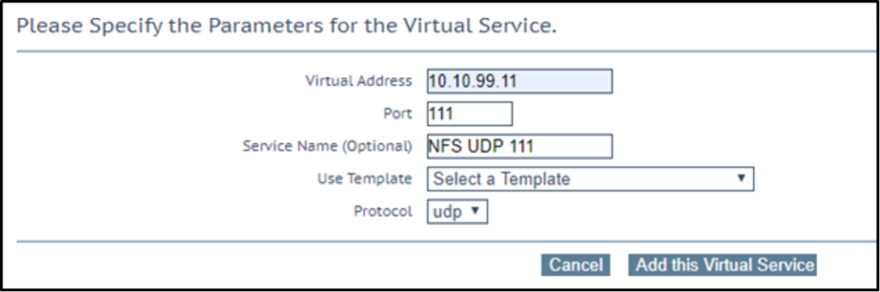
Step 2: Create and configure Virtual Service for UDP 111
- In the main menu, select Virtual Services/ Add New.
- Enter the Virtual IP Address (VIP).
- Enter port 111.
- Provide a name for the Virtual Service.
- Ensure that UDP is selected for protocol.
- Click Add this Virtual Service.
- Expand Standard Options and enter the following:
- Clear the Force L4 check box.
- Under Persistence Options enter Source IP Address.
- Change the Persistence Timeout to 1 Day.
- Change Scheduling Method to least connection.
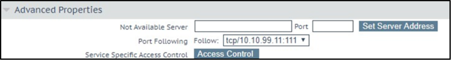
- Expand Advanced Options and enter the following:
- Under Port Following select the TCP Virtual Service created in Step 1.
- Expand Real Servers and enter the following:
- Leave Real Server Check Method as ICMP Ping.
- Click Enhanced Options check box.
- Click Add New …
- Enter the IP address of an ECS Node.
- Ensure Port 111 is entered and click Add This Real Server.
- Repeat these steps for all additional ECS Node IP Addresses.
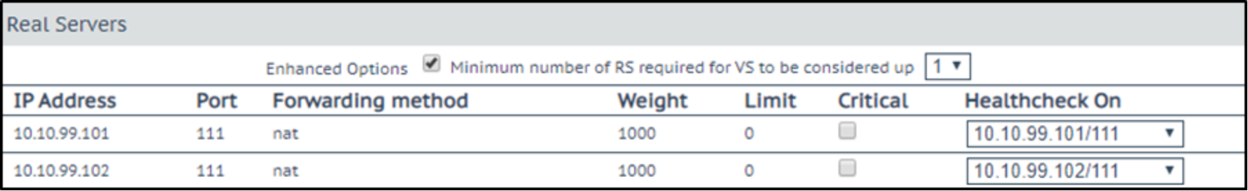
- Once all ECS Nodes have been added, click the Back button to return to the Real Servers section.
- For each Real Server, under Healthcheck On, select the Real Server for the TCP Virtual Service created in Step 1.
Step 3: Create and configure Virtual Service for UDP 2049
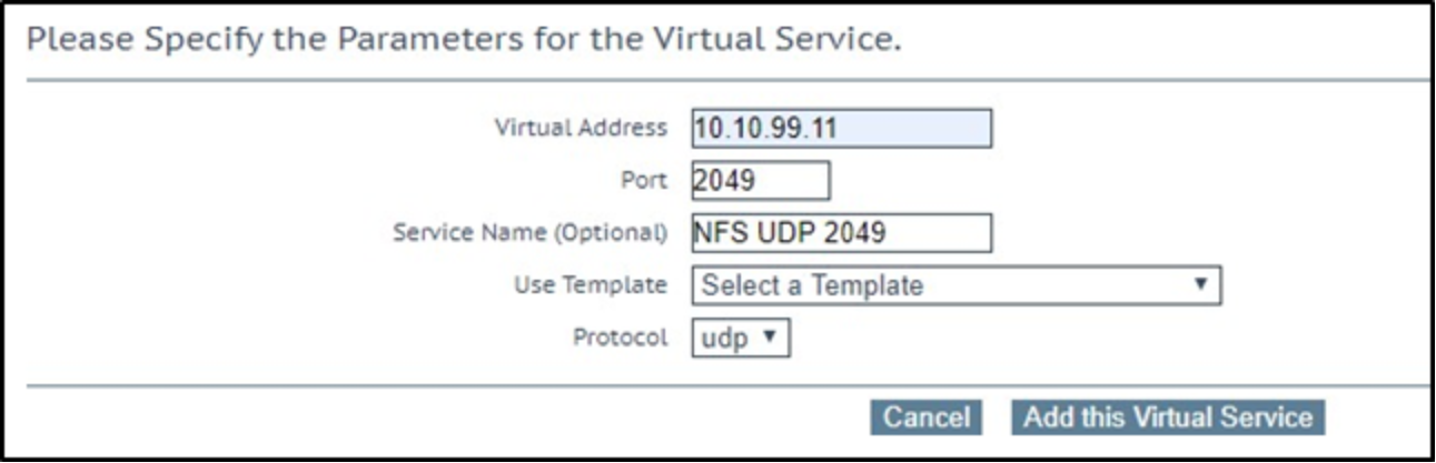
- In the main menu, select Virtual Services/ Add New.
- Enter the Virtual IP Address (VIP).
- Enter port 2049.
- Provide a name for the Virtual Service.
- Ensure that UDP is selected for protocol.
- Click Add this Virtual Service.
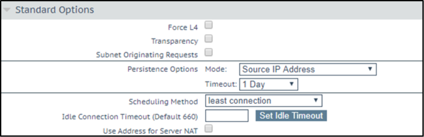
- Expand Standard Options and enter the following:
- Clear the Force L4 check box.
- Under Persistence Options enter Source IP Address.
- Change the Persistence Timeout to 1 Day.
- Change Scheduling Method to least connection.
- Expand Advanced Options and enter the following:
- Under Port Following select the TCP Virtual Service created in Step 1.
- Expand Real Servers and enter the following:
- Leave Real Server Check Method as ICMP Ping.
- Click Enhanced Options check box.
- Click Add New …
- Enter the IP address of an ECS Node.
- Ensure that Port 2049 is entered and click Add This Real Server.
Repeat these steps for all additional ECS Node IP Addresses.
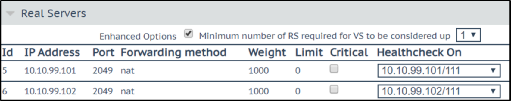
- Once all ECS Nodes have been added, click the Back button to return to the Real Servers section.
- For each Real Server, under Healthcheck On, select the Real Server for the TCP Virtual Service created in Step 1.
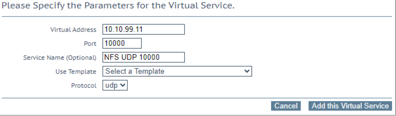
Step 4: Create and configure Virtual Service for UDP 10000
- In the main menu, select Virtual Services/ Add New.
- Enter the Virtual IP Address (VIP).
- Enter port 10000.
- Provide a name for the Virtual Service.
- Ensure UDP is selected for protocol.
- Click Add this Virtual Service.
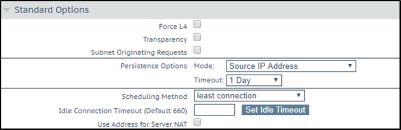
- Expand Standard Options and enter the following:
- Clear the Force L4 check box.
- Under Persistence Options enter Source IP Address.
- Change the Persistence Timeout to 1 Day.
- Change Scheduling Method to least connection.
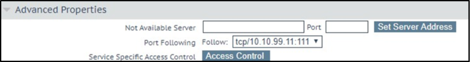
- Expand Advanced Options and enter the following:
- Under Port Following select the TCP Virtual Service created in Step 1.
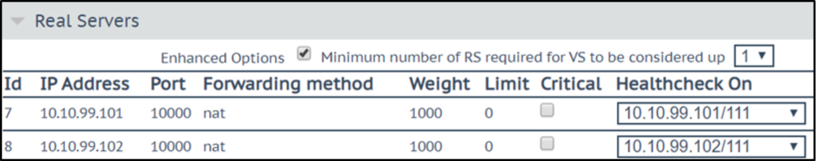
- Expand Real Servers and enter the following:
- Leave Real Server Check Method as ICMP Ping.
- Click Enhanced Options check box.
- Click Add New …
- Enter the IP address of an ECS Node.
- Ensure that Port 10000 is entered and click Add This Real Server.
Repeat these steps for all additional ECS Node IP Addresses.
- Once all ECS Nodes have been added, click the Back button to return to the Real Servers section.
- For each Real Server, under Healthcheck On, select the Real Server for the TCP Virtual Service created in Step 1.
IPv6 to IPv4 translation
IPv6 is the latest version of the Internet Protocol, which identifies devices across the internet, so they can be located. The previous version, IPv4, uses a 32-bit addressing scheme to support 4.3 billion devices however with the explosive growth of the internet, personal computers, smartphones, and the Internet of Things means that the world needs more addresses.
IPv6 uses 128-bit addressing to support 7.9×1028 times as many addresses as IPv4.
Kemp LoadMaster Load Balancers are IPv6 Ready
The LoadMaster can support and translate between IPv4 and IPv6. This does not require the IT department to understand new skills and tricks when handling IPv6 traffic mixed with IPv4 traffic, they do what they should do, deal with the different payloads seamlessly and effectively.
One possible workflow, as shown in the following figure, is where the virtual service uses an IPv6 address name/IP to access the ECS appliance nodes which are configured on an IPv4 network.
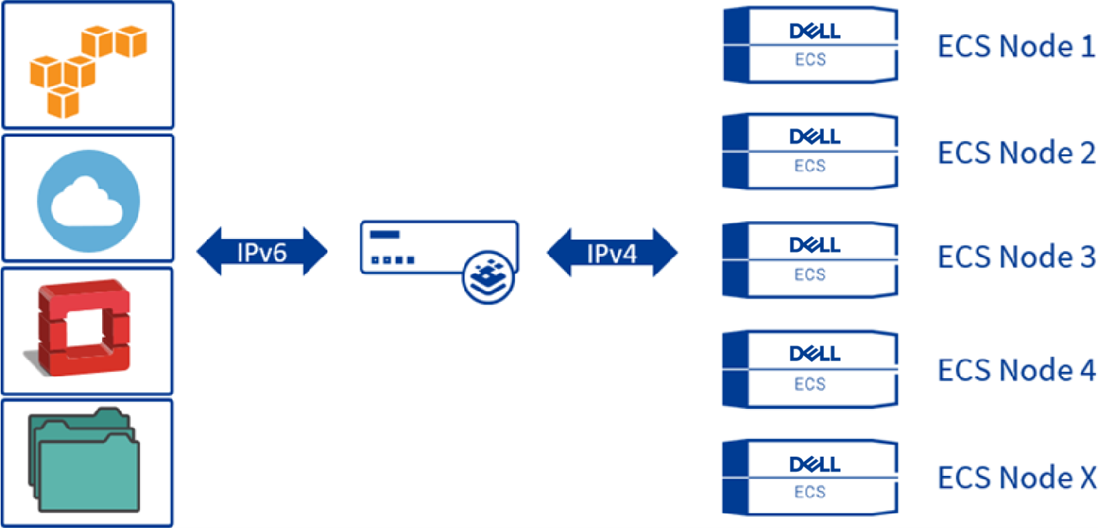
Figure 6. Virtual Service using an IPv6 address with the ECS nodes on IPv4
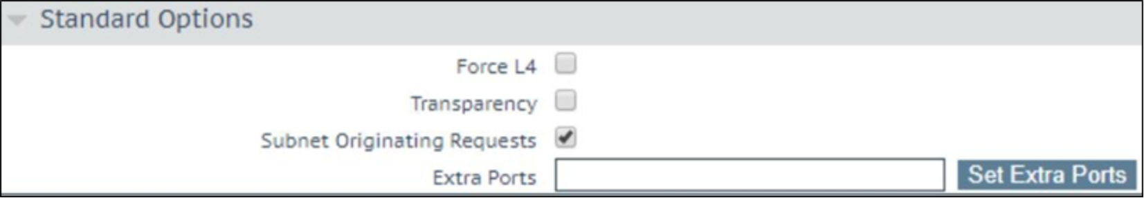
It is recommended to enable Subnet Originating Requests if the LoadMaster is configured with multiple interfaces.
This setting can be configured globally from System Configuration > Miscellaneous Options > Network Options in the main menu or on a per-Virtual Service basis. The following figure shows it as enabled from the virtual service screen.
GEO affinity
Geo-affinity is a feature that focuses on maximizing XOR storage efficiency, while minimizing read-latency impact.
Note: For geo-pinning to work well, you must use a replication group with three or more sites, with low latency between sites. If application performance is more important than maximizing storage efficiency, you should not use geo-affinity, but instead, make sure your application and the ECS bucket are located in the same site.
To take advantage of the storage efficiencies gained on ECS by XOR, data must be written evenly across three or more sites. While writing data evenly across multiple sites leads to increased storage efficiency, reading data in a similar fashion may lead to increased WAN overhead and storage inefficiencies due to caching of remote data. This is because for ECS to provide data that is spread out across multiple sites in a strongly consistent manner, it maintains a record of each object’s owner. The object owner is the VDC in which the object was written and serves as the definitive source and ultimate authority for changes to that object. When an object is read from a non-owner site, ECS must communicate with the owner site across the WAN to determine the latest version of the object.
If you can direct applications to the site where an object was originally written, WAN traffic can be minimized and caching of ECS objects at non-owning sites eliminated or dramatically minimized. This results in higher performance for application workflow and minimal caching of remote data.
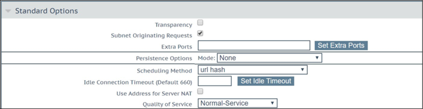
This is where a geo-affinity (or "geo-pinning") algorithm is beneficial. Geo-pinning ensures that all requests for a particular object, be they read or write, are sent to the same site. This feature is built directly into the Kemp LoadMaster specifically for ECS.
To configure LoadMaster Geo-pinning with ECS, select the Scheduling Method url hash under the Standard Options section for your Virtual Service.
When an object is written to the ECS VDC, LoadMaster performs a hash of the object’s path, so it knows where the object was written.
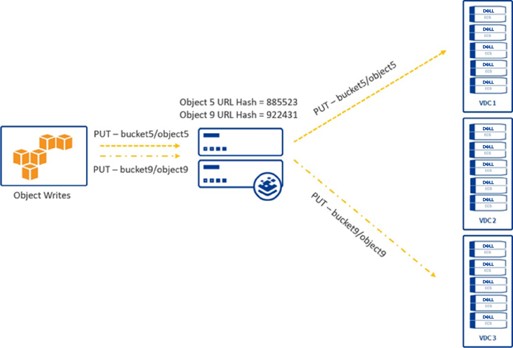
Figure 7. Writing an object using url hash
Objects are always read from the site where it was originally written. This leads to lower WAN traffic, higher performance, and no caching needed for remote data.
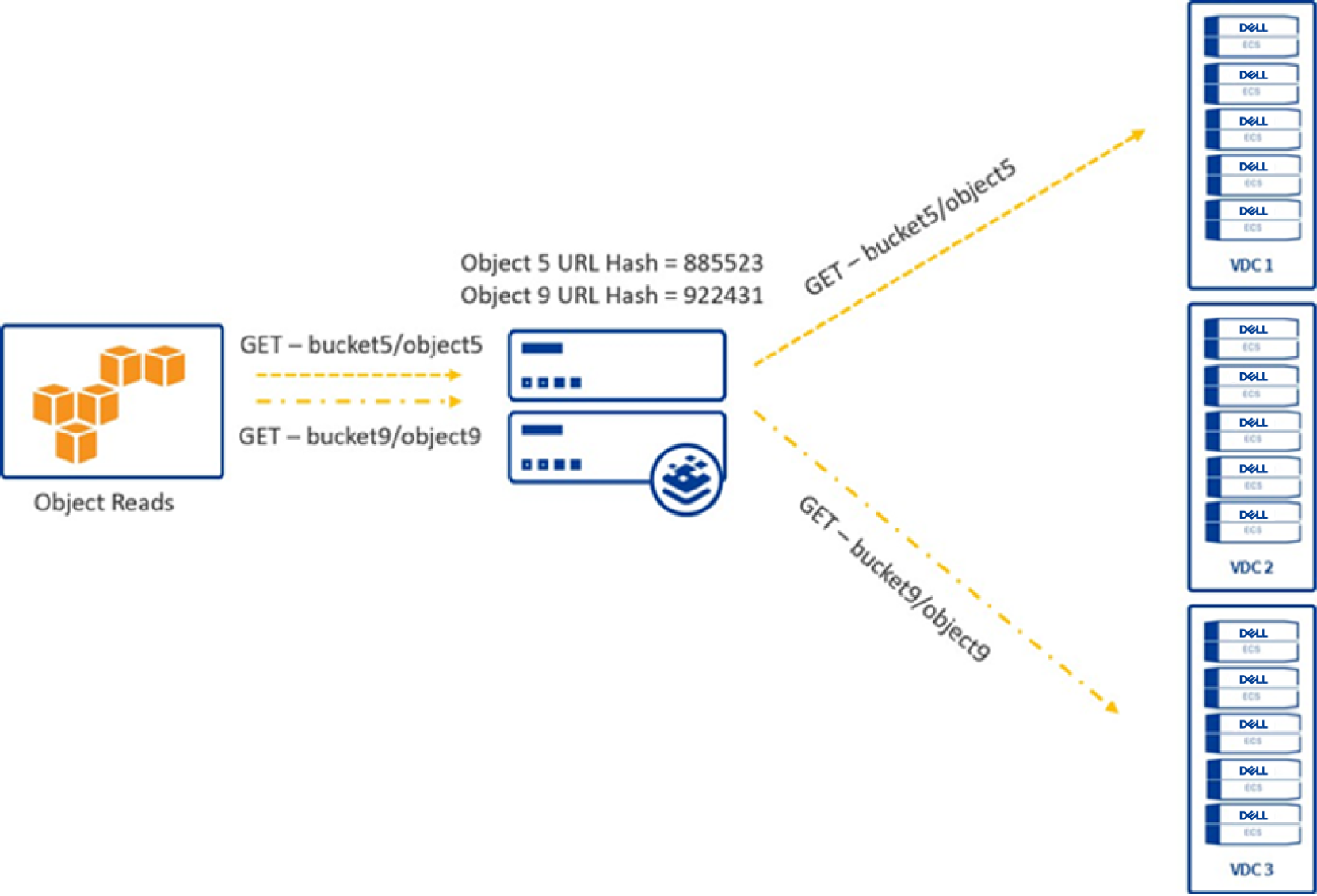
Figure 8. Reading an object using url hash
QoS / Rate limiting
The QoS / Rate Limiting feature was introduced in LoadMaster firmware version 7.2.52 and above. LoadMaster implements QoS (Quality of Service) to rate limit traffic for Dell ECS, therefore providing granular control of resource allocation. This feature helps protect the ECS solution against rogue applications that generate excessive requests and provides a fair and balanced allocation of services across multiple workloads.
QoS configurations can be applied in several different ways on a LoadMaster to deliver the necessary protection and provide optimal performance for the storage solution. The QoS options are provided in the following sections.
For more information about these options and configuration details, visit the Kemp support site to review the QoS/Rate Limiting Feature Description.
Global Limits
Global Limits apply QoS to all requests
- Maximum Concurrent Connections: Limits the maximum number of simultaneous connections allowed to ECS Connection Manager.
- Global Connections Limit: Limits the maximum number of connection attempts per second (CPS).
- Global HTTP Requests Limit: Limits the maximum number of HTTP request attempts per second (RPS).
- Global Bandwidth Limit: Limits the maximum bandwidth for ECS Connection Manager.
Limiter Options
Limiter Options controls the behavior of QoS
- Error Response: By default, ECS Connection Manager drops any connections when the limit is reached. A more graceful response (429 - Too Many Connections or 503 - Service Unavailable) can be sent back to the client or application requesting access.
- Fail on RS / Sub-VS Rate Limiting: If rate limiting is activated for a Real Server (RS) or SubVS, ECS Connection Manager tries to select a different RS/SubVS to use for the connections. Enabling this will force the request to fail with the selected Error Response selected.
- Generate Limiter Statistics: Generates a global summary syslog message every five seconds that contains the state of the limiting subsystem.
- Client Message Repeat Delay: Sets the minimum time after a client is no longer limited before a new message is generated.
Client Limiting
Client Limiting allows rate limiting to be applied based on the source IP address or network of the client or application accessing the storage.
- Maximum Client Concurrent Limit: Limits the maximum number of simultaneous connections allowed by a single client or application. A default (global) setting must be set before applying limits based on specific IP addresses or networks.
- Client Connections/sec Limit: Limits the maximum number of connections per second (CPS) allowed by a single client or application. A default (global) setting must be set before applying limits based on specific IP addresses or networks.
- Client Requests/sec Limit: Limits the maximum number of requests per second (RPS) allowed by a single client or application. A default (global) setting must be set before applying limits based on specific IP addresses or networks.
- Client Bandwidth Limit: Limits the maximum bandwidth allowed by a single client or application. A default (global) setting must be set before applying limits based on specific IP addresses or networks.
URL Based Limiting
URL Based Limiting allows rate limiting to be applied based on the HTTP header of the request. ECS Connection Manager uses Regular Expression (RegEx) to identify these characteristics.
- Request URL: Limits the number of attempts based on the request URL (ECS Bucket Name)
- Host: Limits the number of attempts based on the domain name of the request (ECS Namespace)
- User Agent: Limits the number of attempts based on the User Agent of the request (Operating System, software vendor, or software version).
- Method: Limits the number of attempts based on the HTTP request method. (GET, PUT, DELETE)
Per-Virtual Service Limiting
In addition to being able to configure QoS on a global level, you can also configure limits on a Virtual Service and Sub Virtual Service level.
- Connections per second: Limits the maximum number of connections per second (CPS) allowed for a Virtual Service of Sub Virtual Service.
- HTTP Requests per second: Limits the maximum number of requests per second (RPS) allowed for a Virtual Service of Sub Virtual Service.
- Concurrent Connections: Limits the maximum concurrent connections allowed for a Virtual Service of Sub Virtual Service.
- Bandwidth Limit (Kilobits/sec): Limits the maximum bandwidth allowed for a Virtual Service of Sub Virtual Service.
GSLB Clustering
In environments where a single appliance cannot deliver the necessary throughput or transactions per second, clustering can be leveraged to scale the load balancers. The most effective way to accomplish this level of scale is to deploy the Kemp load balancers in a Global Server Load Balancer (GSLB) Cluster (sometimes referred to as a GEO Cluster). This approach will scale linearly by adding additional load balancers to the cluster and therefore combine resources to deliver the required performance.
GSLB clustering leverages DNS to distribute traffic across the load balancers. As clients and other systems attempt a connection to the published application, DNS delegation is used to direct the resolution of the Fully Qualified Domain Name (FQDN) to GSLB on the load balancers. GSLB will return an IP address to the client based on the scheduling method defined in the configuration and therefore provide proper and efficient distribution across the cluster, to use each node in each ECS VDC.
Health monitoring
The Kemp LoadMaster uses health checks to monitor the availability of the Real Servers. If one of the servers does not respond to a health check within a defined time interval for a defined number of times, the weighting of this server is reduced to zero. This zero weighting has the effect of removing the Real Server from the available Real Servers in the Virtual Service until it can be determined that this Real Server is back online.
Use of the S3 Ping operation is recommended in monitoring ECS S3 service port availability on ECS software running on dedicated ECS hardware. This operation is documented inside the Dell ECS REST API Reference Guide which can be found at Dell Technologies Support.
The S3 Ping operation depends on the fabric layer inside the ECS software. The fabric layer of the ECS software stack provides clustering and system health among other things. It is responsible for keeping required services up and running and managing resources such as disks, containers, and the network. It tracks and reacts to environmental changes such as failure detection and provides alerts related to system health. The S3 Ping operation uses the fabric layer to determine the state of the node’s maintenance mode.
Several health check types are available, however the two types used for the ECS S3 Ping check method are the HTTP and HTTPS protocols.
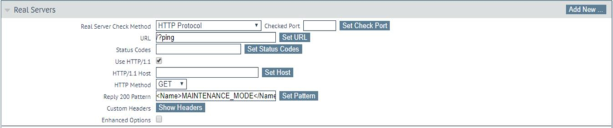
Figure 9. Configuration of the custom ECS health monitor using the HTTP protocol
In this figure, the check method is configured using the HTTP Protocol. Because the S3 Ping operation is an unauthenticated request, no username or password is required. The details to configure are as follows:
- Real Server Check Method: HTTP or HTTPS Protocol
- Use HTTP/1.1 Host: Select the checkbox to enable
- HTTP Method: The S3 Ping operation is a GET command
- Reply 200 Pattern: Set the pattern to ‘<Name>MAINTENANCE_MODE</Name><Status>OFF</Status>’.
If the LoadMaster receives a reply pattern from any of the ECS nodes that does not match the Reply 200 Pattern, the node will be marked as disabled and automatically re-enabled once the pattern matches.
Note: The S3 Ping operation works with both ports 9020 and 9021. It also works for Atmos services.
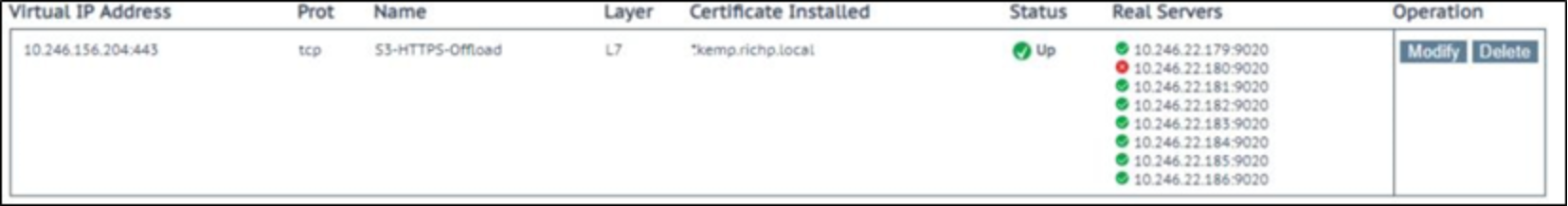
Figure 10. Virtual Service displaying an ECS node that is in Maintenance Mode
Enhanced Options can be configured to determine what the minimum number of ECS nodes that are required to be up for the virtual service to be considered up.
If the Enhanced Options check box is disabled (the default), the Virtual Service is considered available if at least one Real Server is available. If the Enhanced Options check box is enabled, you can specify the minimum number of Real Servers that must be available to consider the Virtual Service to be available.
Organizations may choose to consider a VDC unavailable if less than a required minimum number of nodes are up. A three-node minimum can be chosen because that is the minimum number of nodes required for writes to complete. ECS customers decide on their own logic and configuration on how best to accomplish this.