
F5 Networking Constructs
F5 Networking Constructs
-
A general understanding of the basic BIG-IP network constructs is critical to a successful architecture and implementation. Here is a list of the most common of the BIG-IP networking constructs:
- Virtual Local Area Network (VLAN) - A VLAN is required and associated with each non- management network interface in use on a BIG-IP system.
- Self IP - F5 terminology for an IP address on a BIG-IP system that is associated with a VLAN, to access hosts in the VLAN. A self IP represents an address space as determined by the associated netmask.
- Static self IP - A minimum of one IP address is required for each VLAN in use in a BIG-IP system. Static self IP addresses are unit-specific in that they are unique to the assigned device. For example, if two BIG-IP devices are paired together for HA, each device’s configuration will have at least one self IP for each VLAN. The static self IP configuration is not sync’d or shared between devices.
- Floating self IP - Traffic groups, which are logical containers for virtual servers, can float between BIG-IP LTM devices. Floating self IP addresses are created similarly to static addresses, except that they are assigned to a floating traffic group. With this, during failover the self IP floats between devices. The floating self IP addresses are shared between devices. Each traffic group that is part of an HA system can use a floating self IP address. When in use the device actively serving the virtual servers on the traffic group hosts the floating self IP.
- MAC Masquerading Address - An optional virtual layer two Media Access Control (MAC) address, otherwise known as a MAC masquerade, which floats with a traffic group.
MAC masquerade addresses serve to minimize ARP communications or dropped packets during a failover event. A MAC masquerade address ensures that any traffic destined for the relevant traffic group reaches an available device after failover has occurred, because the MAC masquerade address floats to the available device along with the traffic group. Without a MAC masquerade address, on failover the sending host must relearn the MAC address for the newly-active device, either by sending an ARP request for the IP address for the traffic or by relying on the gratuitous ARP from the newly-active device to refresh its stale ARP entry.
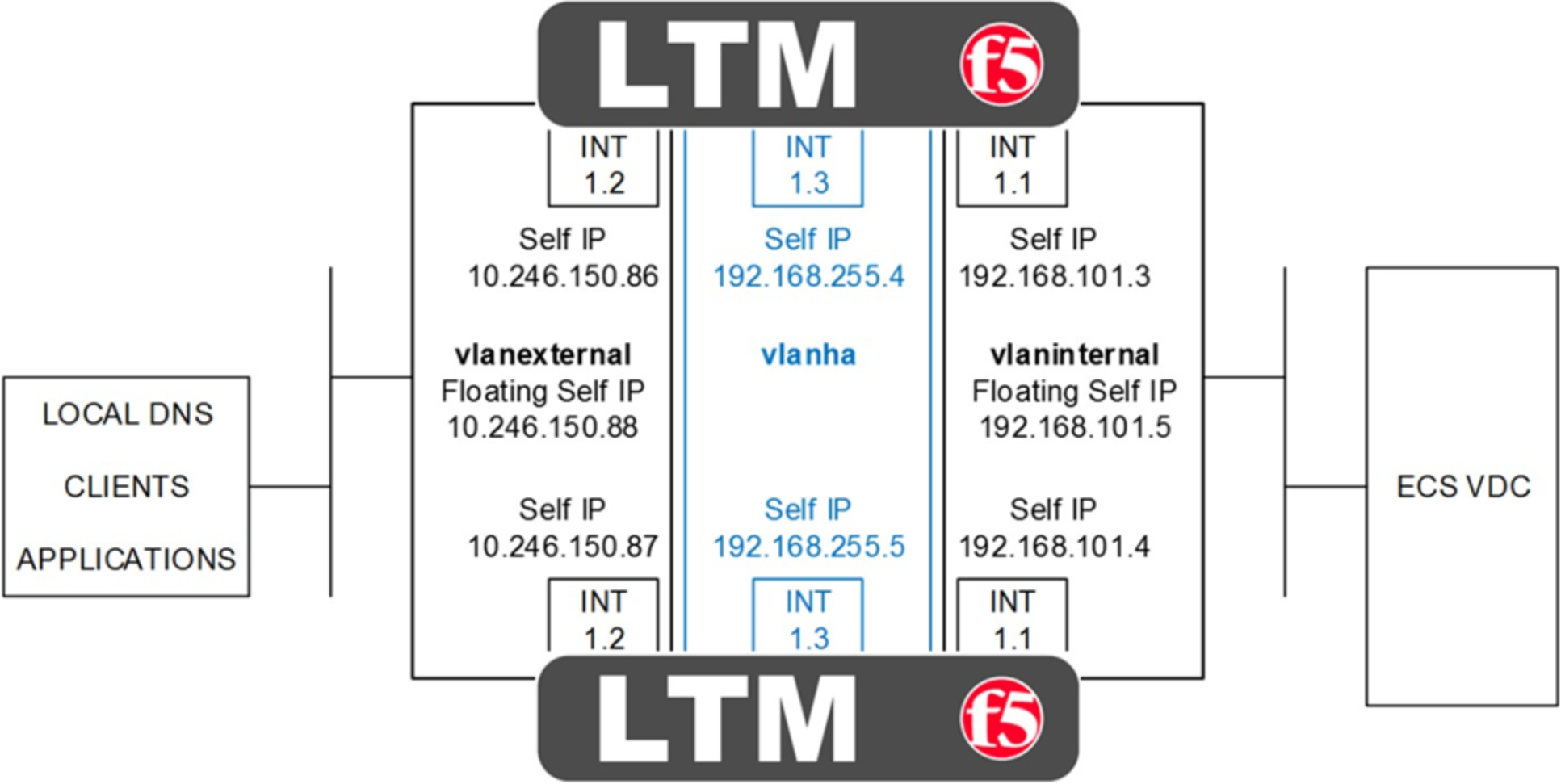
Figure 2. HA pair of LTM with physical interfaces, VLAN and self IP addresses
Figure 2 above shows a HA pair of LTM. The physical interfaces as shown are 1.1, 1.2, and 1.3. In addition each device has a management interface which is not shown. Each interface has an associated VLAN and self IP address. Floating self IP addresses are created in redundant configurations as is a VLAN dedicated for HA. Not shown are any MAC masquerading addresses. MAC masquerading addresses are associated with traffic groups. Traffic groups are explained in the next section on F5 device redundancy.
BIG-IP LTM, like with other Application Delivery Controllers, can be deployed in a variety of deployment architectures. Two commonly used network deployment architectures are:
- One-arm - A one-arm deployment is where the LTM has only a single VLAN and interface configured for application traffic. The LTM both receives and forwards traffic using a single network interface. The LTM sits on the same subnet as the destination servers. In this scenario applications direct their traffic to virtual servers on the LTM which use virtual IP addresses that are on the same subnet as the destination nodes. Traffic received by the LTM is forwarded to the target ECS node.
- Two-arm - The examples we use throughout this paper are two-arm implementations. A two-arm deployment is where the LTM sits on the same subnet as the destination servers, as above, but also listens for the application traffic on an entirely different subnet. The LTM uses two interfaces, each on unique subnets, to receive and forward traffic. In this scenario two VLANs exist on the LTM, one for external, client-side traffic, and the other one for internal, server-side traffic. Figure 2 above is an example of a two-arm architecture.
Traffic routing between the client, LTM, and ECS nodes is important. Two primary options for routing exist for the pool members, in our case, ECS nodes:
- The default route on the ECS nodes point to a self IP address on the LTM. With this, as the nodes return traffic to the clients, because the default route points to the LTM, traffic will route back to the clients the same way it came, through the LTM. In our lab setup we set the default route on the ECS nodes to point to the self IP address on the LTM. For Site 1, our site with a pair of LTMs configured for HA, we used the floating self IP address as the default gateway. For Site 2, the ECS nodes point to the self IP address of the single LTM.
- The default route on the ECS nodes point to an IP address on a device other than the LTM, such as a router. This is often referred to as Direct Server Return routing. In this scenario application traffic is received by the node from the LTM, but due to the default route entry, is returned to the client bypassing the LTM. The routing is asymmetrical and it is possible that clients will reject the return traffic. LTM may be configured with address and port rewriting disabled which may allow clients to accept return traffic. F5 documentation or experts should be referenced for detailed understanding.