
F5 BIG-IP LTM
F5 BIG-IP LTM
-
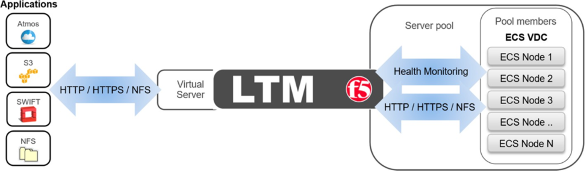
Figure 5. LTM high-level overview
A local traffic manager, as seen in the middle of Figure 5 above, listens and receives client application traffic on one or more virtual servers. Virtual servers are generally identified by a FQDN and port, for example, s3.site1.ecstme.org:9020. Virtual servers process traffic for either one service port, or all service ports.
Virtual servers are backed by one or more pools. The pools have members assigned to them. The pool members consist of ECS nodes and identified by their hostname and port, for example, ecs-1-1:9020. The configuration determines whether all traffic is directed to a specific port on pool members or whether the port of the original request is kept.
An LTM makes a decision for each application message it receives on a virtual server to determine which specific pool member in the virtual server’s configured pool(s) should receive the message. The LTM uses the configured load balancing algorithm to make this determination.
The LTM uses health monitors to keep an up-to-date status of all individual pool members and their relevant services. As a node or node’s required service(s) become unavailable the LTM ceases to send application traffic to the pool member and subsequent messages are forwarded to the next available pool member per the configured load balancing algorithm.
In this document examples are shown with virtual servers and pool members that service single ports, S3 with Secure Socket Layer (SSL) at port 9021, for example. It is possible for a virtual server to listen traffic on all service ports. This would allow for all application traffic to point to one virtual server that services all the related ports. F5 BIG-IP systems have a configuration element called iRule. Using iRules allows administrators to detail rules, for example, to only process traffic on specific ports and to drop all other traffic. Using an iRule could allow a virtual server to listen on all ports but only process traffic for ports 111, 2049, and 10000, the NFS-related ports ECS uses. Readers are encouraged to research iRules to determine if they are worthwhile for use in their BIG-IP configuration.
Note: Local applications may use the S3-specific application ports, 9020 and 9021. For workflows over the Internet it is recommended to use ports 80 and 443 on the front end and ports 9020 and 9021 on the backend. This is because the Internet can handle these ports without problem. Using 9020 or 9021 may pose issues when used across the Internet.
Example: S3 to Single VDC with Active/Standby LTM Pair
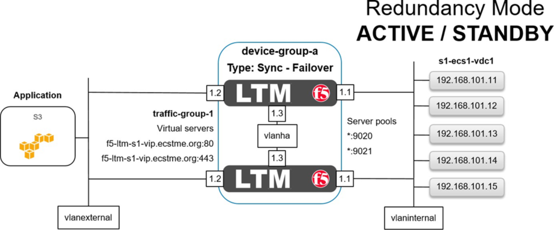
Figure 6. LTM in active/standby redundancy mode
Figure 6 above shows the basic architecture for this example of an S3 application access to ECS via an Active/Standby HA pair of LTM at a single site. A client application is shown on the far left. In our case it resides in the same subnet as the LTM but it could be on any local or global network. Each of our LTM devices has four network interfaces. The first, not shown above, is used for management access. Interfaces 1.1 are assigned to a VLAN named vlaninternal. In general load balancing terms this is often also called the back-end or server-side network. Interfaces 1.2 are assigned to VLAN vlanexternal. Generally this is referred to as the front-end or client-side network. Interfaces 1.3 are assigned to VLAN vlanha. The HA VLAN is used for high availability functionality along with synchronization of the device’s configuration and client connection mirroring. A BIG-IP device group, device-group-a, in our case, logically contains both devices. The device group’s failover type, sync-failover, is configured with the redundancy mode set to Active/Standby. In Active/Standby redundancy mode, one device actively processes all application traffic at any given time. The other device is idle and in standby mode waiting to take over processing application traffic if necessary. On the far right is our VDC at Site 1. All of the ECS nodes are each put in to two BIG-IP pools as referenced in Figure 6 above using an asterisk. One pool is configured with port 9020 and the other pool for 9021.
In between the client and LTM, a BIG-IP traffic group, traffic-group-1, in our example, is shown. It contains two virtual servers, one for each type of S3 traffic we provide access for in this example. Applications will point to the FQDN and appropriate port to reach the VDC.
In between the LTM and VDC two pools are shown, one for each service port we required. Each of these pools contain all VDC nodes. Not shown is the health monitoring. Monitoring will be discussed further down as the example continues.
Here is a general overview of the steps in this example:
- Configure the first LTM.
- Configure the second LTM and pair the devices for HA.
Step 1: Configure the first LTM.
GUI screenshots are used to demonstrate LTM configuration. Not shown are the initial F5 BIG-IP Virtual Edition basic setup of licensing and core infrastructure components such as NTP and DNS. Table 11 below shows these details used for each LTM device.
Table 11. LTM base device details
Devices
System ›› Platform ›› Configuration
Hostname: Management IP
f5-ltm-s1-1.ecstme.org: 172.16.3.2
f5-ltm-s1-2.ecstme.org: 172.16.3.3
f5-ltm-s2-1.ecstme.org: 172.16.3.5
NTP
System ›› Configuration : Device : NTP
Time servers
10.254.140.21
DNS
System ›› Configuration : Device : DNS
DNS lookup servers list
10.246.150.22
DNS search domain list
localhost, ecstme.org
Figure 7 below shows three VLANs and associated network interfaces used. At this point in our example, and during single device configuration, the third interface and associated VLAN is configured but not used until later in the HA example. VLAN configuration is simple and consists of naming the VLAN and assigning a physical network interface, either tagged or untagged, as the resource. We use an untagged interface as each interface in our design only services one VLAN. None of the devices aside from the F5 BIG-IP DNS and LTM in our test environment use VLAN tagging. If an interface belongs to multiple VLANs it should be tagged. For more information on tagged versus untagged interfaces, and when to use each, refer to F5 documentation. In addition, refer to Dell EMC ECS Networking and Best Practices whitepaper here: https://www.emc.com/collateral/white-paper/h15718-ecs-networking-bp-wp.pdf.
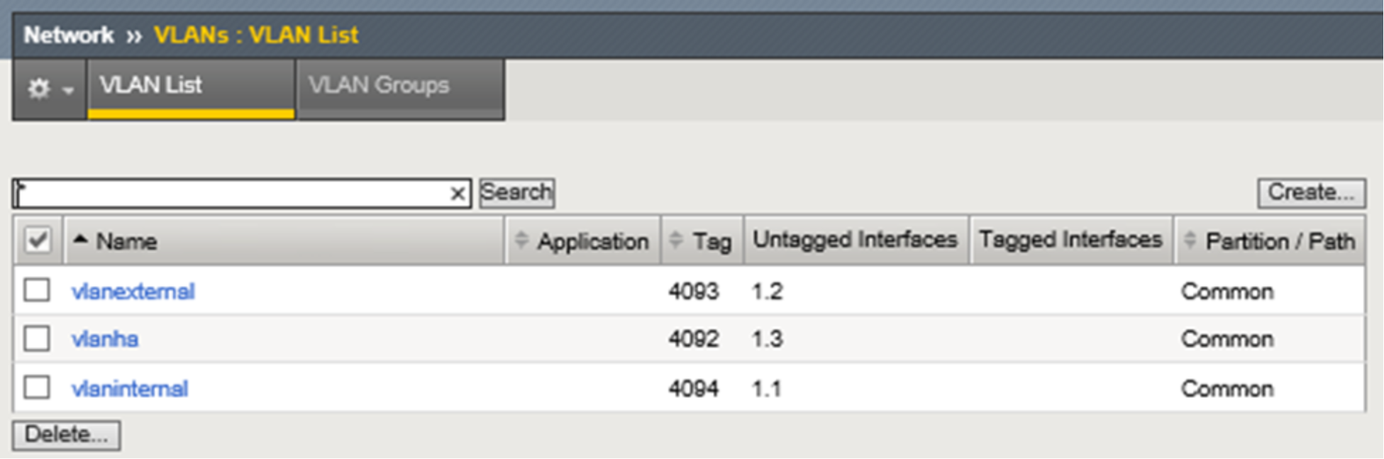
Figure 7. LTM VLANs with interfaces
Figure 8 below shows the non-management network interfaces on this LTM. As mentioned above, during single device deployment only two interfaces are required to carry application traffic in a typical two-arm architecture as described earlier in the F5 Networking Constructs section. The third, in our example, is configured in advance in preparation for HA.
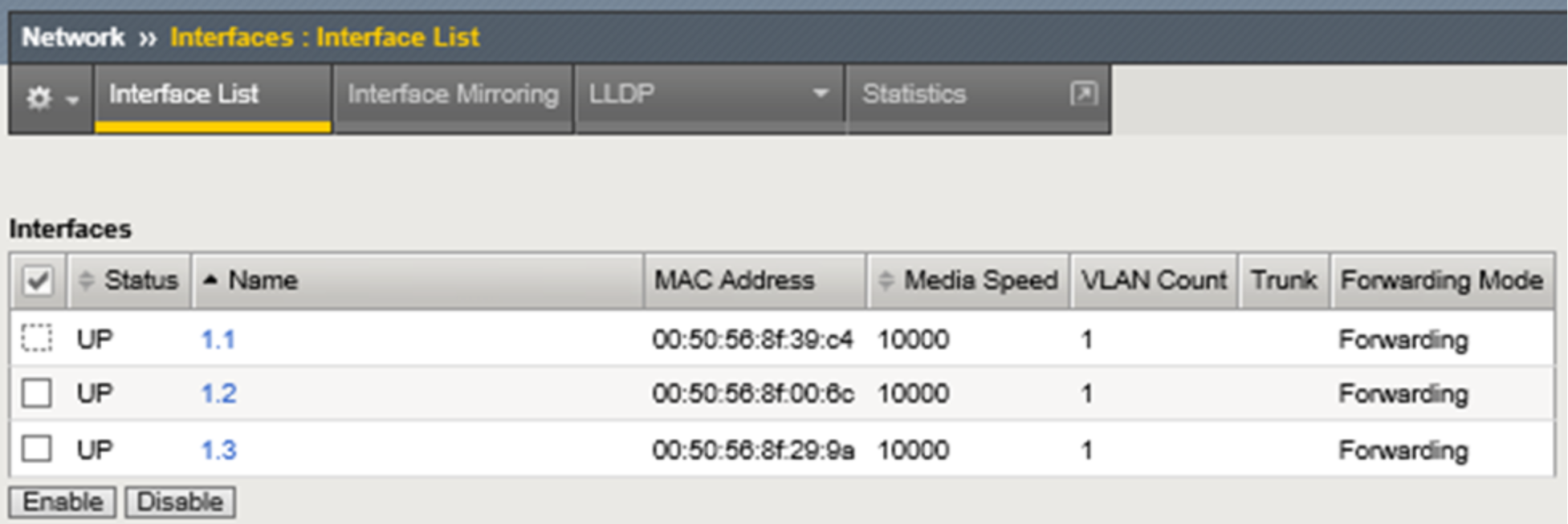
Figure 8. LTM non-management network interfaces with MAC addresses
Figure 9 below shows the self IP addresses required for this example. Each of the interfaces used for application traffic are assigned two self IP addresses. The local addresses are assigned to the interface and are assigned to the built-in traffic group named traffic-group-local-only. In preparation for HA a floating self IP address is also created for each interface carrying application traffic. In HA they will move between devices as needed in service to the active unit. The floating self IP addresses are associated with traffic group named traffic-group-1. Also shown in the graphic is the self IP address for HA. At this point, in a single device deployment configuration, only two self IP addresses are required for a two-arm architecture, one for each VLAN and interface that will handle application traffic. Later when we synchronize configuration between the LTM pair, the static self IP addresses will not be part of the settings shared between the two devices. That is, these self IP addresses are local only to the device they’re created on.
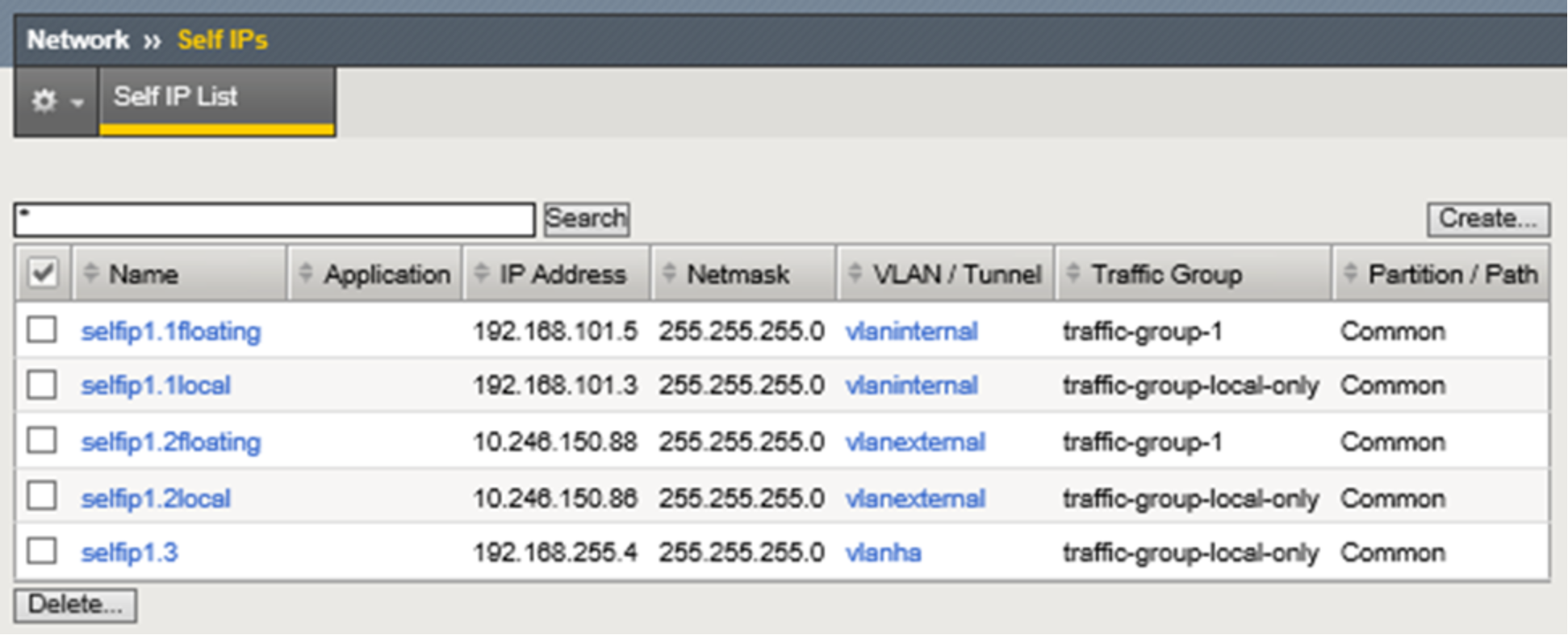
Figure 9. LTM static and floating self IP addresses
Figure 10 below begins to show the creation of one of the pools.
Note: Prior to performing any L3-L7 application configuration, such as the creation of pools, it may be advisable to create and verify the device trust first. See Step 2 below. This would allow for the verification of L2/L3 sanity prior to troubleshooting application traffic issues such as failing monitors.
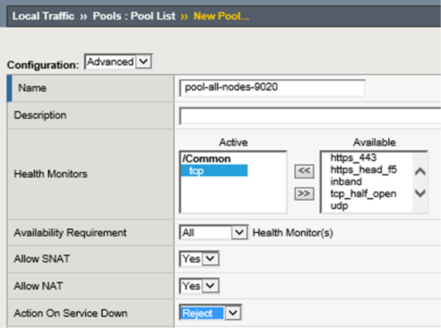
Figure 10. LTM pool creation
The pool is named, assigned a health monitor, and configured with “Reject” as the desired “Action on Service Down” method. Built-in TCP health monitoring is used for the lab. All of the other settings in the upper ‘Configuration’ section for new pool creation dialog are default. When using F5 with a real hardware appliance the best practice is to use S3 Ping. This is explained further and demonstrated in Appendix A: Creating a Custom S3 Monitor.
The "Action on Service Down" setting controls LTM's connection management behavior when a monitor transitions a pool member to a DOWN state after it has been selected as the load balancing target for a connection. The best option is entirely dependent on that application's client and server implementations.
The possible options are:
- None - Default setting. The LTM will continue to send data on established connections as long as client is sending and server is responding.
- Reject - Most commonly used option. Used to explicitly close both sides of the connection when the server goes DOWN. This option often results in the quickest recovery of a failed connection since it forces the client side of the connection to close.
- Drop - The LTM will silently drop any new client data sent on established connections.
- Reselect - The LTM will choose another pool member if one is available and rebind the client connection to a new server-side flow.
In the lower section of the new pool creation dialog the load balancing method is selected, and pool members are assigned. Figure 11 below shows a list of all available load balancing methods. We use the often utilized least connections option. Consult F5 directly for the specific details and reasons why any of the available options may be desirable for a given workload.
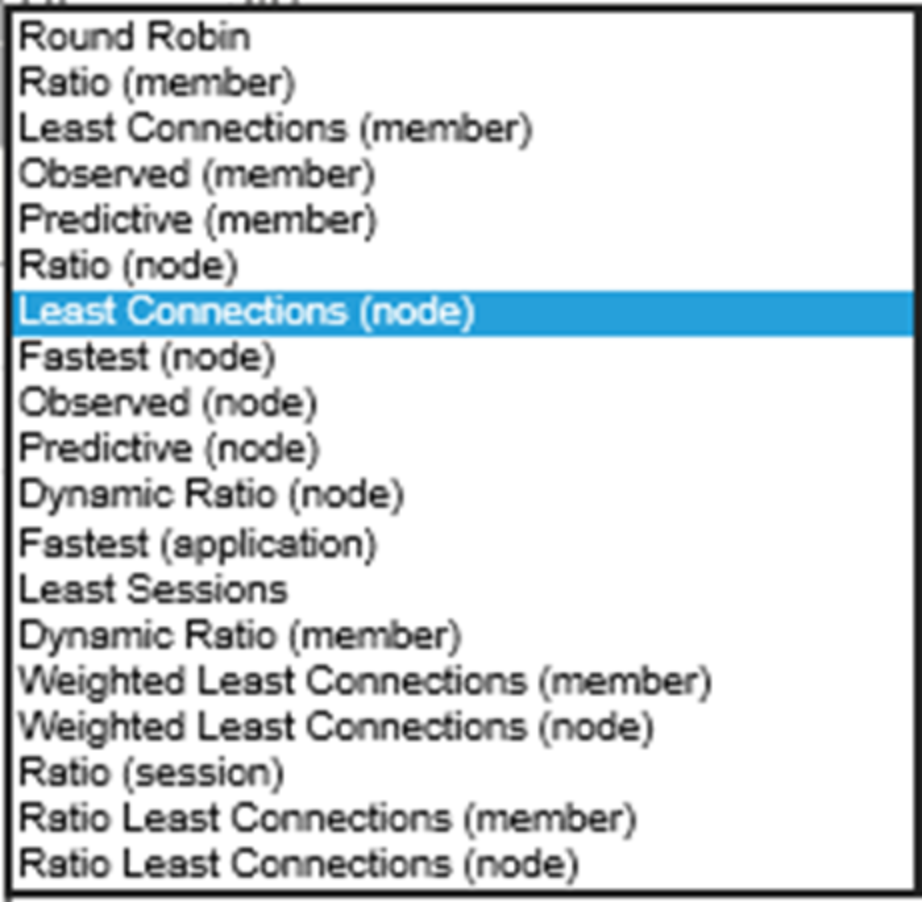
Figure 11. LTM load balancing methods available
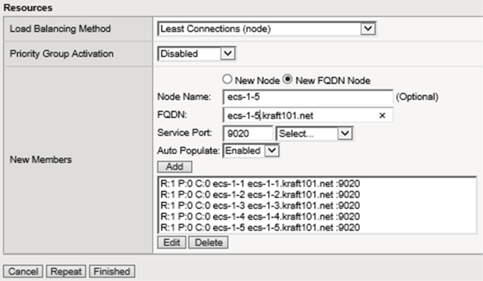
Figure 12. LTM pool final configuration
Figure 12 above shows the final configuration selections with all pool members. The S3 with SSL pool is configured in the same manner using port 9021. The S3 with SSL pool allows for the encryption of traffic between the client and ECS node using an ECS-generated certificate. In the lab we use a self-signed certificate. In production environments it is recommended to use a certified signing authority.
It is generally recommended however that SSL connections be terminated at the LTM. Use of SSL encryption during transport is CPU intensive and the F5 BIG-IP software is specially built to handle this processing efficiently. F5 hardware also has dedicated Application-Specific Integrated Circuits (ASIC) to further enhance efficiency in processing this traffic. SSL can be terminated at ECS, the LTM, or both. By terminating SSL at both places, a client will establish a secure connection to the F5 using an F5 certificate, and the LTM will establish a secure connection to the ECS node using the ECS certificate. Twice the amount of processing is required when encrypting each of the two connections individually. Traffic encryption options should be analyzed for each application workflow. For some workflows, for example when no personally identifiable information is transmitted, no encryption may be suitable. All traffic will pass over the wire in clear text fashion and no encryption-related CPU processing is required. For other workflows encryption on the external connection is appropriate but non-encrypted connectivity on the internal network may be fine. Some banks and other highly secure facilities may use encryption for each of the two connections.
Figure 13 below shows both pools in the system. Although there are only five ECS nodes, ten members are shown for each pool. This is because the system lists both ephemeral and non-ephemeral members. Per the F5 documentation, during pool creation, when the default setting of “Auto Populate on” is used, the system creates an ephemeral node for each IP address returned as an answer to a DNS query. Also, when a DNS answer shows that the IP address of an ephemeral node doesn't exist anymore, the system deletes the ephemeral node.
These two pools can handle all of our S3 traffic needs. Traffic to pool members listening on port 9020 is not encrypted. Traffic to pool members listening on port 9021 is encrypted.
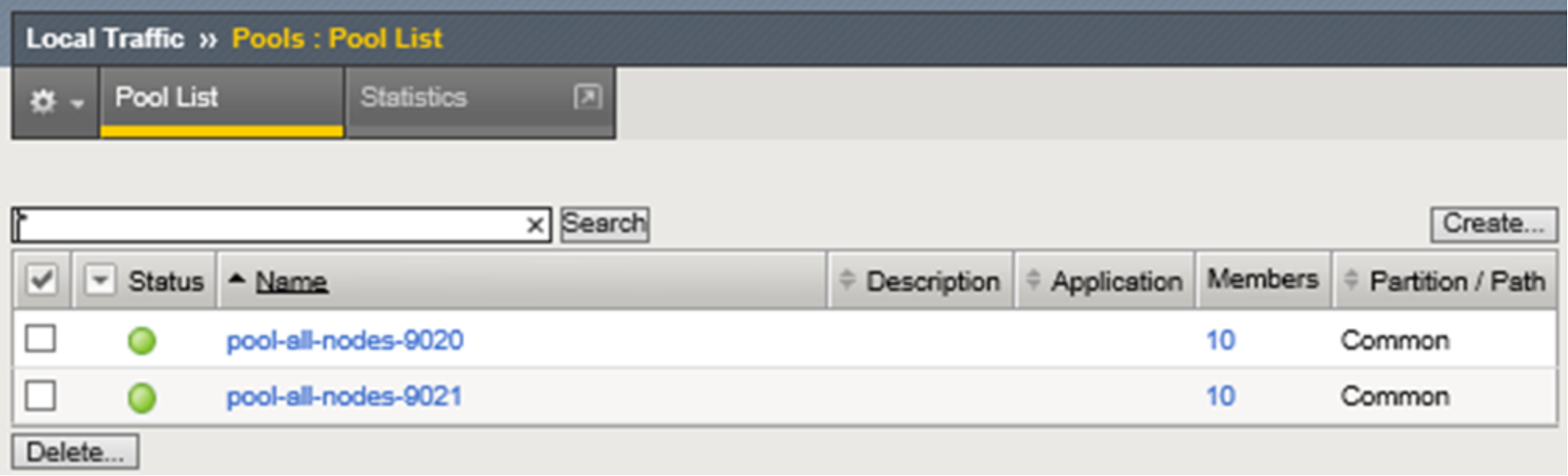
Figure 13. LTM S3-related pools
Next is the creation of a virtual server. Figure 14 below shows the assigned name, destination address, and service port for an S3 virtual server that serves non-encrypted traffic. A source address or network can optionally be added as well. The destination IP address shown is the Virtual IP address that will be created on the system. Client applications will point to this IP address. We optionally assign a name to the address in DNS to allow clients to use a FQDN.
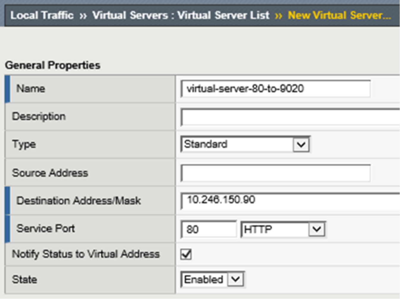
Figure 14. LTM new virtual server creation dialog
The type of virtual server we use is Standard. Several other types exist and Figure 15 shows the list of options provided in the GUI. F5 documentation should be reviewed to understand the available virtual server types. We choose Standard however using another type of virtual server, such as Performance (HTTP), may be more suitable for production access.
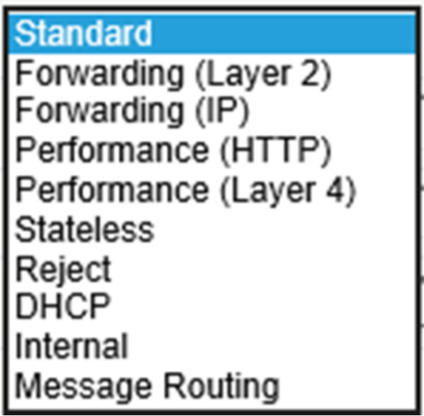
Figure 15. LTM virtual server options
The remaining values are not shown. For this example, TCP is selected for protocol. Other protocol options exist and are UDP, SCTP, or All. We’ll use “All” option when configuring NFS-related virtual servers in the NFS example. The pool we selected was pool-all-nodes-9020. We also selected a “Default Persistence Profile” of source_addr. Figure 16 below shows a list of available values for this setting. F5 documentation should be consulted for details of each to see if they are more appropriate for a given workload. We selected and recommend source_addr as the persistence profile because it keeps a client’s application traffic pinned to the same pool member which allows for efficient use of ECS cache. We generally recommend source_addr as the persistence profile for all virtual servers in use with ECS. Source address affinity persistence directs session requests to the same server based solely on the source IP address of a packet. In circumstances where many applications on a few number of clients connect to ECS through an LTM another persistence profile may be better suited because it could cause an uneven load distribution across ECS nodes. As with all configuration choices, be sure to understand the options available to make appropriate traffic management decisions for each workflow and architecture deployed.
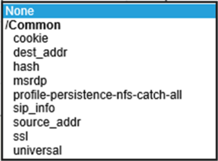
Figure 16. LTM persistence profile options
Figure 17 below shows the vitual server for non-encrypted S3 traffic and some other virtual servers configured to this point. Three other virtual servers exist on this LTM and are not covered in our example. By default BIG-IP LTM has a default deny all policy. In order for traffic to traverse through an LTM a rule must explicitly exist. The topology used in our lab does not have a router in the mix so we created virtual servers to allow traffic to be forwarded as needed. The additonal rules shown allow, for example, our two ECS VDCs to communicate with each other and for the underlying CentOS to access the Internet for application binaries and such.
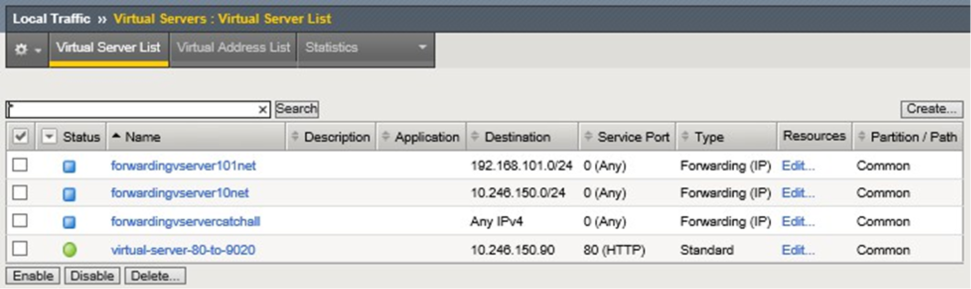
Figure 17. Configured virtual servers
Step 2: Configure second LTM, pair the devices for HA.
We add a second LTM to the same network as the first and configure the network interfaces similar to the first, using unique self IP addresses. To create the pair, in the WebUI, Device Management is selected and Device Trust then Device Trust Members is chosen. The Add button is selected in the Peer and Subordinate Devices section to add the peer device. This was done from our first LTM set up, however, it can be accomplished via either device. The second device’s management IP address, administrator username, and administrator password are entered. A retrieve Device Information button appears as shown below in Figure 18. Once clicked, some of the remote devices information is displayed. These actions are only required on one of the devices.
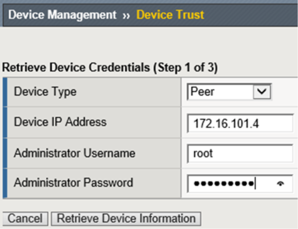
Figure 18. Retrieve device information button
After the two devices trust each other, a device group can be created. In our environment we called the device group device-group-a. The group type of Sync-Failover is chosen and both devices are added as members. The Network Failover box is checked. For now we will sync manually so none of the other boxes require check marks. A traffic group, traffic-group-1, is created automatically during this process.
Device Management, Devices, Device List, select (self), leads to Properties page along with Device Connectivity list menu. The list menu contains, ConfigSync, Failover Network and Mirroring. For the ConfigSync configuration we select our HA local address. For the Failover Network configuration, we choose HA for the unicast address. For Mirroring we chose HA IP address for the Primary, and vlanexternal address for the secondary. The connection state mirroring feature allows the standby unit to maintain all of the current connection and persistence information. If the active unit fails and the standby unit takes over, all connections continue, virtually uninterrupted.
With all of the required configuration we sync the first LTM to the group. This is done via Device Management, Overview, select self, choose sync device to group, and clicking Sync. Then we can sync the group to the second device.
Here is a table which provides a summary all configuration elements to this point.
Table 12. LTM configuration elements
Device Group
Device Management ›› Device Groups
Name
device-group-a
Group type
Sync-Failover
Sync type
Manual with incremental sync
Members
f5-ltm-s1-1, f5-ltm-s1-2
Traffic Group
Device Management ›› Traffic Groups
Name
traffic-group-1
Pools
Local Traffic ›› Pools
Name
pool-all-nodes-9020
Health monitors
tcp
Action on service down
Reject
Members
ecs-1-1:9020, ecs-1-2:9020, ecs-1-3:9020, ecs-1-4:9020, ecs-1-5:9020
Virtual Servers
Local Traffic ›› Virtual Servers
Name
virtual-server-80-to-9020
Type
Standard
Destination address
10.246.150.90
Service port
9020
Protocol
TCP
Default pool
pool-all-nodes-9020
Default persistence profile
source_addr
At this point we have two LTM devices configured for HA at Site 1. In this Active/Standby scenario only one device handles application traffic at any time. Client connections and application sessions are mirrored to the standby device to allow failover with minimal interruption. Applications point to the single virtual server name or IP address. With source_addr as the default persistence configuration chosen, connections from each client are directed by the LTM to a single ECS node. If that ECS node should fail the connections are reset and subsequent application traffic is pointed to the next indicated ECS node.
Table 13 below shows the LTM-related DNS entries.
Table 13. LTM-related DNS entries
DNS record entry
Record type
Record data
Comments
f5-ltm-s1-1.ecstme.org
A
10.246.150.86
F5 LTM Site 1 (1 of 2) self IP address
f5-ltm-s1-2.ecstme.org
A
10.246.150.87
F5 LTM Site 1 (2 of 2) self IP address
f5-ltm-s1-floater.ecstme.org
A
10.246.150.88
F5 LTM Site 1 floating self IP address
f5-ltm-s1-virtual.ecstme.org
A
10.246.150.90
F5 LTM Site 1 virtual IP address
Organizations may choose to consider a VDC unavailable if less than a required minimum number of nodes are up. A three node minimum may be chosen as it is the minimum number of nodes required for writes to complete. ECS customers decide on their own logic and configuration on how best to accomplish this.
One approach may involve the creation of an object whose existence can be queried on each node. A monitor which queries for the object on each node can be customized to look for a minimum number of successful responses in order to consider the pool healthy.
When considering this type of rule, it is important to understand the significance of enabling ADO during bucket creation. If enabled, objects can be accessed RW (or RO if file-enabled) after 15 minutes (by default) when the site where the object was written is not reachable. If not enabled, object access is unavailable if the object owner's site is not reachable.
If a rule exists to send requests to an alternate site when a subset of a site's nodes are unavailable, but the site remains reachable, a TSO wouldn't be triggered but some requests will fail even if they are sent to alternate site. Losing more than one node is rare so it is not generally recommended to create rules for this.
Example: LTM-terminated SSL Communication
Three primary configuration options are available for encrypting client traffic to ECS. They are:
- ECS-terminated SSL connectivity. End-to-end traffic encryption between client and ECS.
- LTM-terminated SSL connectivity. Encrypted traffic between the client and LTM. No encryption between LTM and ECS.
- ECS-terminated and LTM-terminated SSL connectivity. Traffic is encrypted twice, first between client and LTM, and second between LTM and ECS.
As previously mentioned, SSL termination is a CPU intensive task. LTM hardware has dedicated hardware processors specializing in SSL processing. LTM software also has mechanisms for efficient SSL processing. It is recommended, when appropriate, to terminate SSL on the LTM and offload encryption processing overhead off of the ECS storage. Each workflow should be assessed to determine if traffic requires encryption at any point in the communication path.
Generally, storage administrators use SSL certificates signed by a trusted Certificate Authority (CA). A CA- signed or trusted certificate is highly recommended for production environments. For one, they can generally be validated by clients without any extra steps. Also, some applications may generate an error message when encountering a self-signed certificate. In our example we generate and use a self-signed certificate.
Both the LTM and ECS software have mechanisms to produce the required SSL keys and certificates. Private keys remain on the LTM and/or ECS. Clients must have a means to trust a device’s certificate. This is one disadvantage to using self-signed certificates. A self-signed certificate is its own root certificate and as such client systems will not have it in their cache of known (and trusted) root certificates. Self-signed certificates must be installed in the certificate store of any machines that will access ECS.
The first step in configuring any of the three SSL connectivity scenarios described above is the generation of the required SSL keys and associated signed certificates. Each SSL key and certificate pair can then be added to a custom SSL profile on the BIG-IP LTM. Custom SSL profiles are part of the virtual server configuration.
SSL connectivity between a client and LTM requires the creation of a key and certificate pair for the LTM. This pair is then added to an SSL profile and associated with the virtual server which hosts the associated traffic.
Note: Although heavily CPU intensive, terminating a client's connection twice, both on the LTM and then again on an ECS node, may be required if complete end-to-end encryption is required, AND, http header information requires processing by the LTM. For example, when an iRule is used to hash an object's name to determine the destination pool for which to direct the application's request to
The simplest and most common use is for the client to LTM traffic to be encrypted and LTM to ECS is not. In this scenario the LTM offloads the CPU-intensive SSL processing from ECS.
Here is a general overview of the steps we’ll walk through in this example:
- Create SSL key and self-signed certificate on the LTM.
- Create a custom SSL profile and configure with the key/certificate pair.
- Create a virtual server for LTM-terminated SSL connectivity to ECS.
Step 1: Create SSL key and self-signed certificate on the LTM.
A single self-signed certificate is used for all three LTM devices in our lab deployment. Subject Alternate Names (SAN) are populated during the creation of the certificate to include all possible combinations of names and addresses that may be used during client connectivity through the LTM to ECS. Using a single certificate pair for all devices isn’t necessary. A key and certificate can be uniquely created for each BIG-IP device. Because self-signed certificates are used in our lab, additional client-side steps are required to allow the LTM to be trusted by the client. In production environments, or, when using widely recognized public signing authorities such as CA, there shouldn’t be any need for special client-side accommodations to accept the granting authority.
Creating a self-signed digital certificate on an LTM device can be done at the command prompt using OpenSSL, or, via the WebUI by clicking on the Create button located by navigating to the System, Certificate Management, Traffic Certificate Management, SSL Certificate List page.
A new SSL Certificate configuration page is presented and the Common Name (CN) and SAN fields are populated. The end result is a new self-signed certificate which is then exported and imported in to the other two LTM devices. Figure 19 shows the fields as used in the lab. The SSL key was also exported and imported to all three LTM under the same name for consistency, along with the new certificate.
Note: SSL keys can be generated on any device with the proper tools such as OpenSSL.
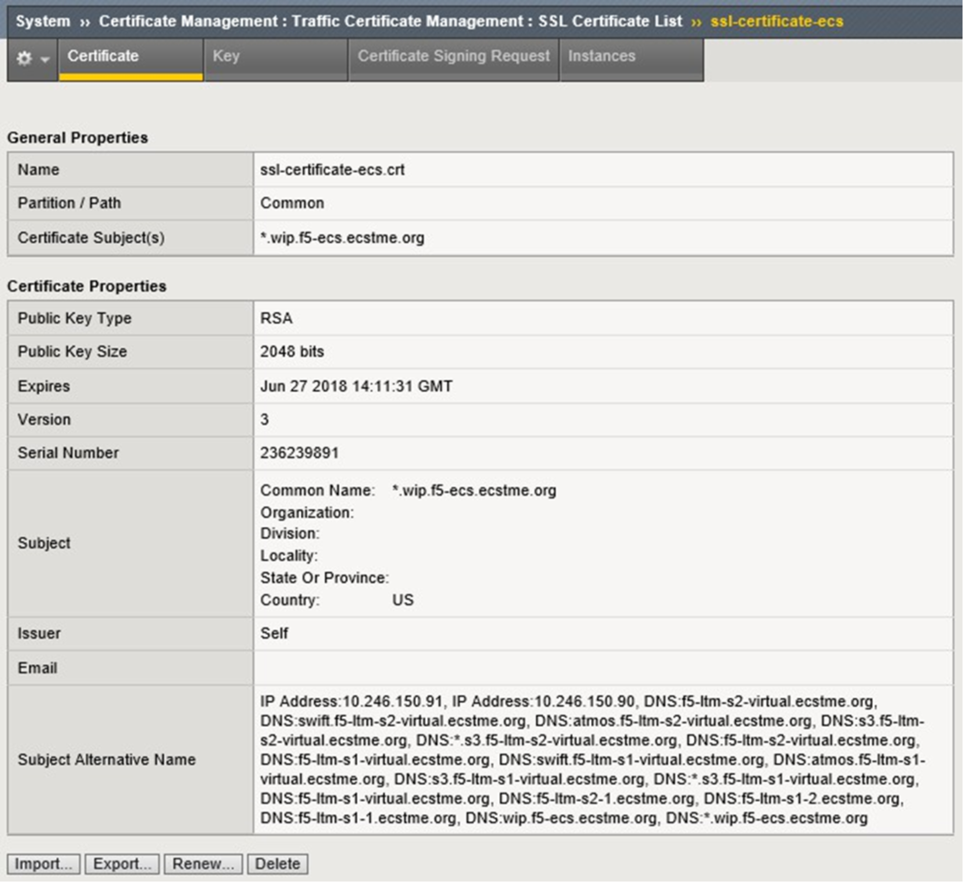
Figure 19. Custom SSL certificate fields
At this point a newly-created self-signed certificate exists on all three LTM in the lab deployment. Clients will be able to negotiate an encrypted session to any of the lab LTMs via SSL using any of the names or IP addresses in the SAN field.
Step 2: Create a custom SSL client profile and configure with the key/certificate pair. There are two types of SSL profiles for use in LTM virtual servers:
- Client SSL Profile. A client SSL profile is used to enable SSL from the client to the virtual server.
- Server SSL Profile. A server SSL profile is used to enable SSL from the LTM to the pool member.
In this example we create a new custom SSL client profile to allow for encrypted communication between the client and LTM.
A new profile can be generated by clicking the Create button on the Local Traffic, Profiles: SSL: Client page. Profile configuration has four sections: General Properties, Configuration (Basic or Advanced), Client
Authentication, and SSL Forward Proxy (Basic or Advanced). In the General Properties section a name is provided for the new profile along with the parent profile to be used which serves as a template. Figure 20 shows the values used for the example.
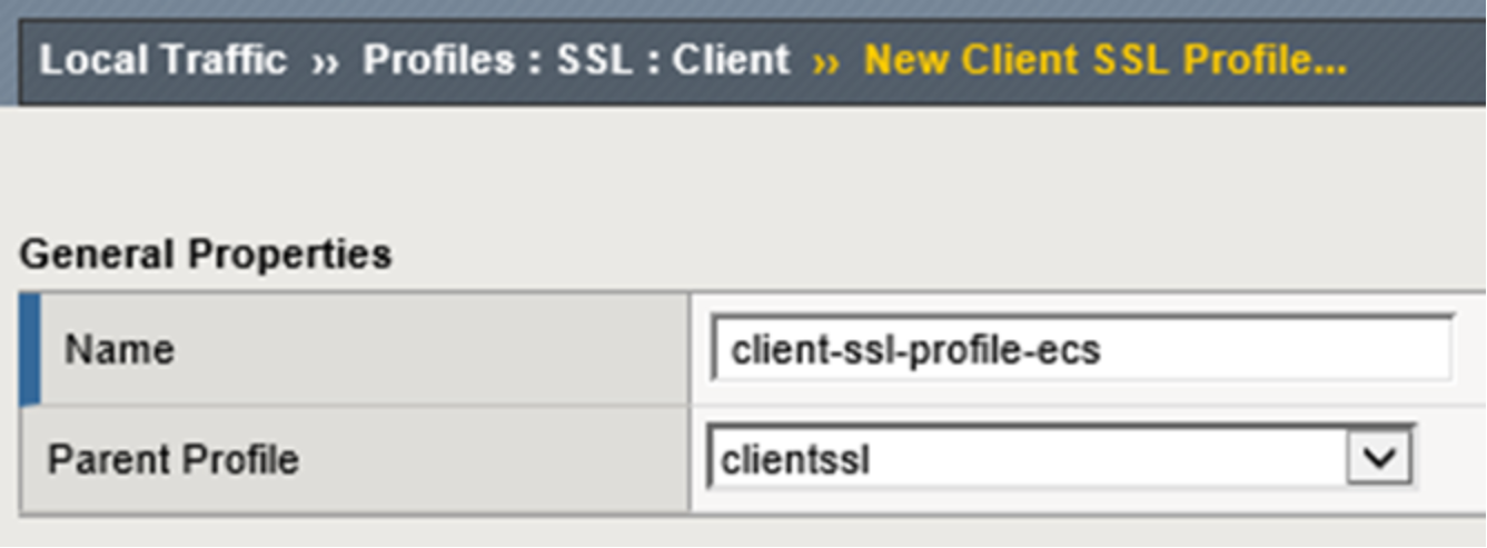
Figure 20. LTM client SSL profile naming
Only two other values are edited for the example, specifying the ssl-key-ecs.key and the ssl-certificate-ecs.crt files as shown in Figure 21 below.
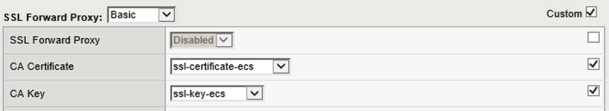
Figure 21. CA certificate and key selection
The custom SSL client profile is generated on all three LTM in our reference deployment. ConfigSync could also be used to deploy the profile. Each LTM has a similar new custom SSL Client profile. This profile can now be associated with a virtual server.
Step 3: Create a virtual server for LTM-terminated SSL connectivity to ECS.
A second S3 virtual server is created in this example to demonstrate the scenario where an LTM offloads the SSL processing. Using this virtual server client application traffic will be encrypted between the clients and LTM and unencrypted between the LTM and ECS.
Similar to the first virtual server creation in the example above, Figure 22 below shows the General Properties section with values used.
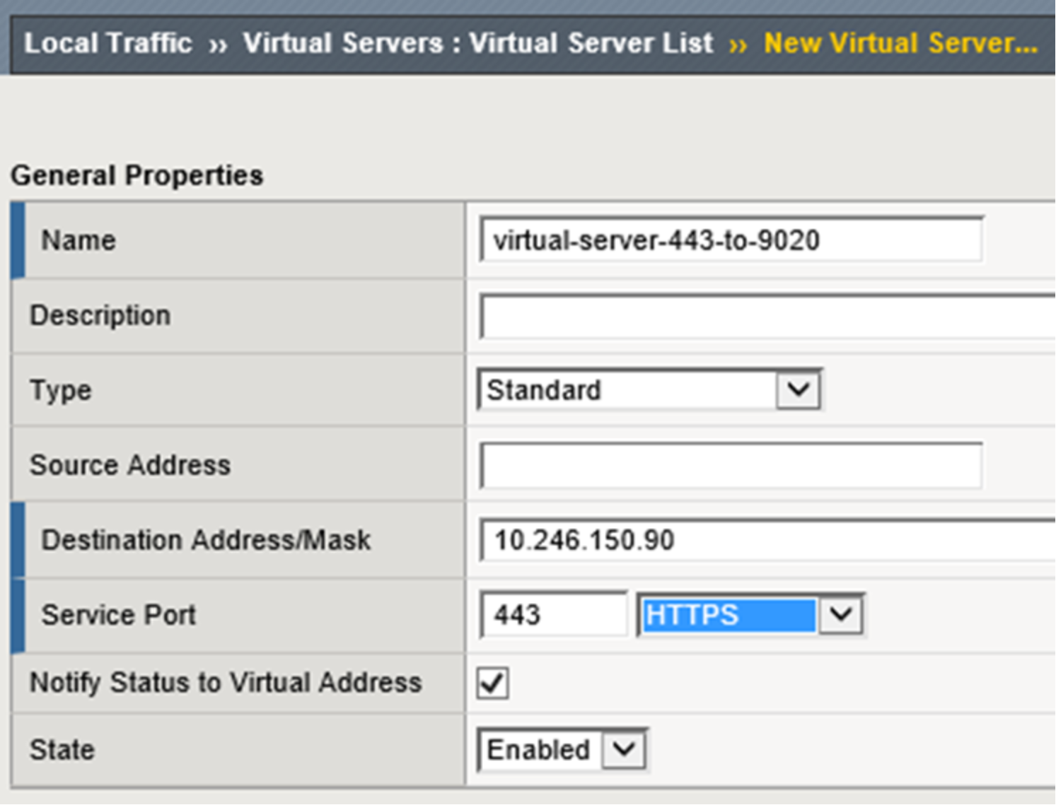
Figure 22. LTM virtual server general properties section
Only a single change is required in the configuration section, it is the addition of the SSL Profile (Client) value as shown in Figure 23 below.
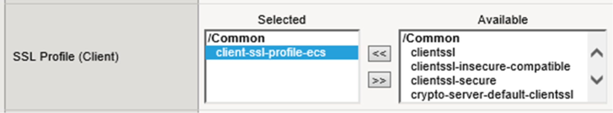
Figure 23. LTM virtual server with client SSL profile selection
The default pool and persistence profile are identical to those used during the creation of the virtual-server- 80-to-9020 as shown in Figure 24 below.
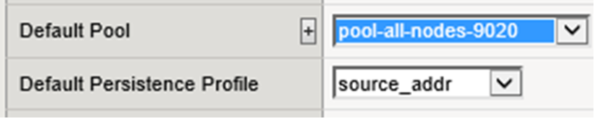
Figure 24. LTM default pool and persistence profile selection
This virtual server can also be created on site 2’s LTM. Site 1 configuration requires synchronization to the other LTM at this point.
Additional virtual servers can be created for S3 traffic. A SSL Server Profile can be created to allow encryption of traffic between the LTM and ECS nodes. When you apply a Server SSL profile to a virtual server, the BIG-IP system acts as an SSL client.
Another common virtual server used is for encrypting traffic between the client and ECS, where the LTM performs no SSL processing, and the LTM simply forwards traffic to the ECS as-is. ECS nodes establish sessions directly with the clients. This requires the use of a pool with members that service port 9021.
Similar to the virtual servers created for S3 application traffic, virtual servers can be created for Atmos and Swift protocols using the appropriate ports.
Example: NFS via LTM
It is not recommended to balance NFS traffic load across ECS nodes without using persistence. This is because ECS nodes locally cache specific metadata attributes that NFS clients often query and read ahead (prefetch) NFS file data. These caching mechanisms allow fewer trips to disk which reduces system response time and generally improve sequential read throughput. Load balancing each client's NFS traffic severely reduces the benefits of these ECS cache mechanisms.
A client application should be tied to a single ECS node for the duration of the session. Only during a failure should the connection between client and ECS be moved to another ECS node.
To configure an LTM to provide HA for NFS access to ECS, the basic configuration steps listed below should be performed. The steps can also be found with more detail at the following link: https://support.f5.com/kb/en-us/solutions/public/6000/700/sol6749. It is important to note the F5 link does not mention use of a health monitor during the creation of the NFS-specific pool. A pool configured without a monitor has no mechanism to trigger the LTM to direct clients to working nodes. It is possible to monitor a pool serving NFS-related services using one or more custom monitors, up to one for each protocol and port combination required, and the requirement for one or more of them to be available on a node to receive traffic. It is recommended and common practice to use one monitor for NFS pools for check TCP on port 2049.
A virtual server configured for all service ports listens for any traffic bound for any port which is not configured elsewhere. In the examples provided in this paper we have created virtual servers configured for ports 80, 443, 9020, 9021. Optionally additional virtual servers could be created for the ports used with Atmos and Swift applications. This example demonstrates an NFS wild card (all ports) virtual server that listens on all other ports. The NFS wild card (all ports) pool will direct all traffic, not just which is directed to the NFS- related ports, to pool members. As mentioned above iRules can be put in place to further configure actions to take for traffic received on ports that either is or isn’t explicitly serviced.
The overview of steps used in this example are as follows:
- Create an NFS custom monitor.
- Create the NFS pool.
- Create two NFS-related custom profiles.
- Create the NFS virtual server.
Step 1: Create the NFS custom monitor.
For health monitoring one custom monitor is created for TCP traffic to port 2049. The monitor is associated with the pool.
Note: A TCP monitor without receive string is ok as it only monitors the availability of the daemon, not its health. A UDP monitor requires a receive string to do anything at all. F5 documentation or experts should be referenced for detailed understanding. UDP monitors are not recommend for use with ECS.
Step 2: Create the NFS pool.
One pool is created for NFS traffic in our example. All ECS nodes are members of the pool and it is configured to listen on all ports. The NFS monitor associated with the pool and the action on service down value is set to reject.
Figure 25 below shows the Load Balancing Method (Least Connections) and member list for the pool.
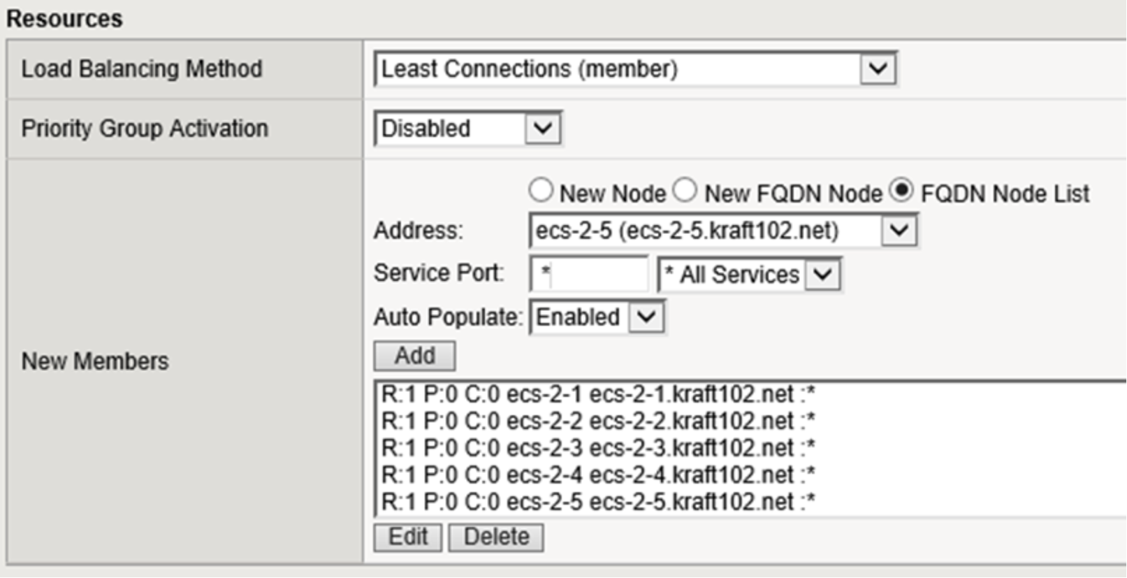
Figure 25. LTM pool load balancing and member selection
Step 3: Create two custom profiles.
A custom persistence profile is recommended for use by the NFS virtual server. Source Address Affinity as the Persistence Type is recommended along with a custom Timeout value of 86400 seconds to provide for a client to be persisted to the same NFS server for a 24-hour persistence period (adjust this value as appropriate for your environment). Figure 26 below shows the configuration used during the creation of the custom persistence profile.
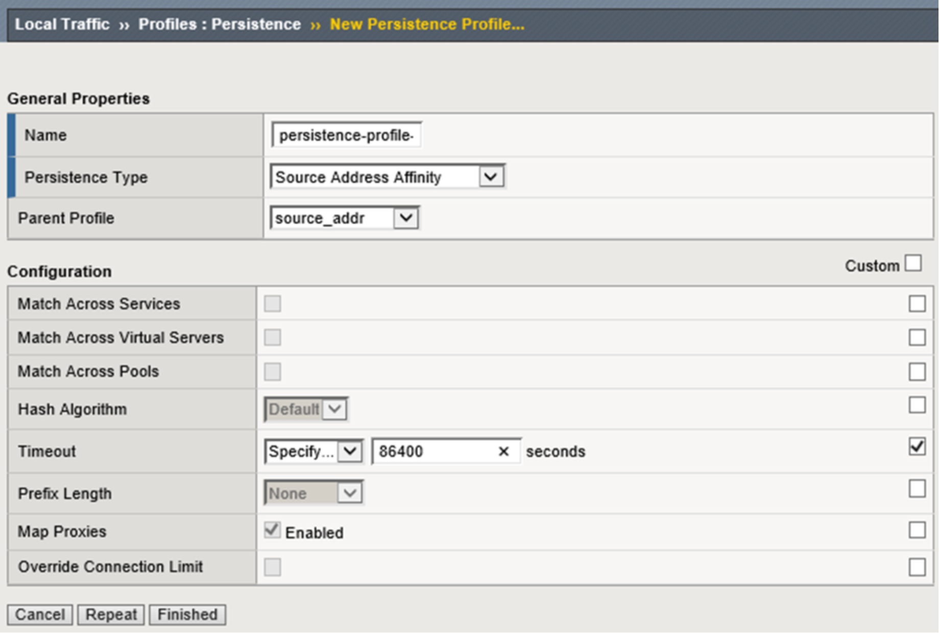
Figure 26. Custom persistence profile creation
A custom FastL4 protocol profile with an Idle Timeout value of 3600 seconds is recommended to be used by the NFS virtual server. This allows for a connection to be idle for 1 hour before the BIG-IP system will close the connection (adjust this value as appropriate for your environment). Figure 27 below shows the configuration used during the creation of the custom protocol profile.
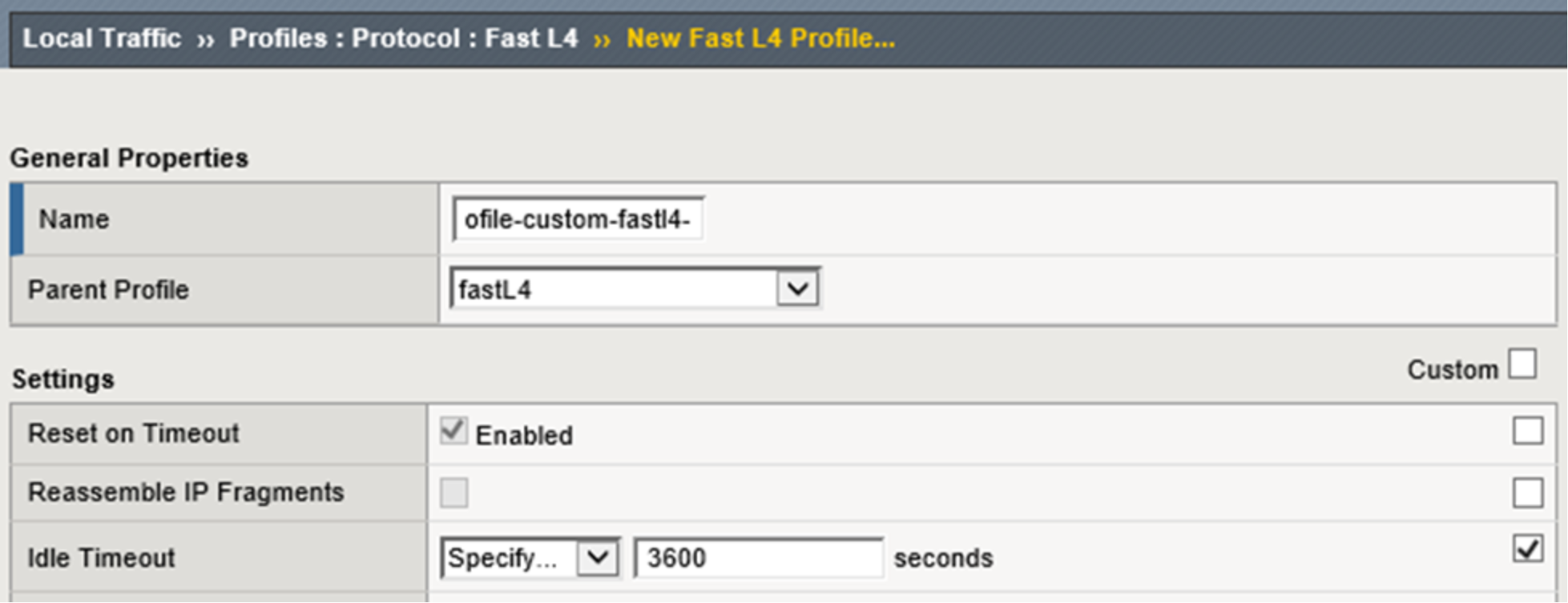
Figure 27. Figure 27 - Custom Fast L4 profile creation
Step 4: Create the NFS virtual servers.
A wildcard virtual server is configured as the NFS virtual server. Performance (Layer 4) as the Type. All ports are configured as the Service Port. Figure 28 below shows the General Properties configuration used for this example.
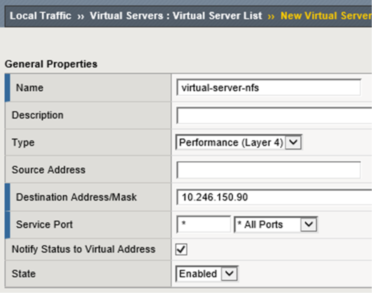
Figure 28. LTM NFS virtual server general properties configuration
Within the Configuration section *All Protocols as the Protocol and the newly-created custom FastL4 profile you created earlier as the Protocol Profile (Client). Figure 29 below shows the Configuration sections of the NFS-specific virtual server created.
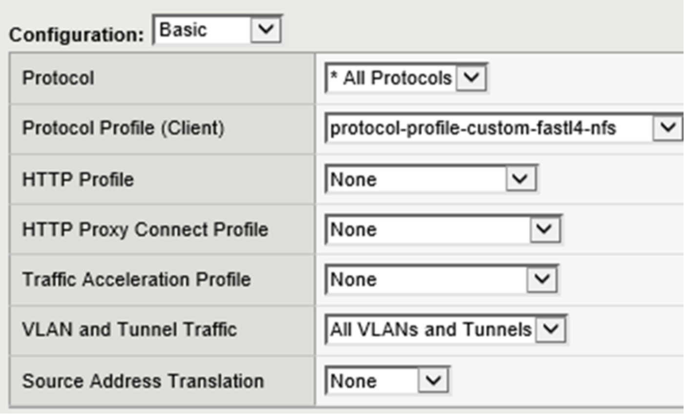
Figure 29. LTM NFS basic configuration selections
Within the Resources section select the NFS pool created earlier as the Default Pool and the Persistence profile created earlier as the Default Persistence Profile. Figure 30 below shows the Resources section of the Resources section where the pool for NFS is set as the default pool and the default persistence profile is configured.
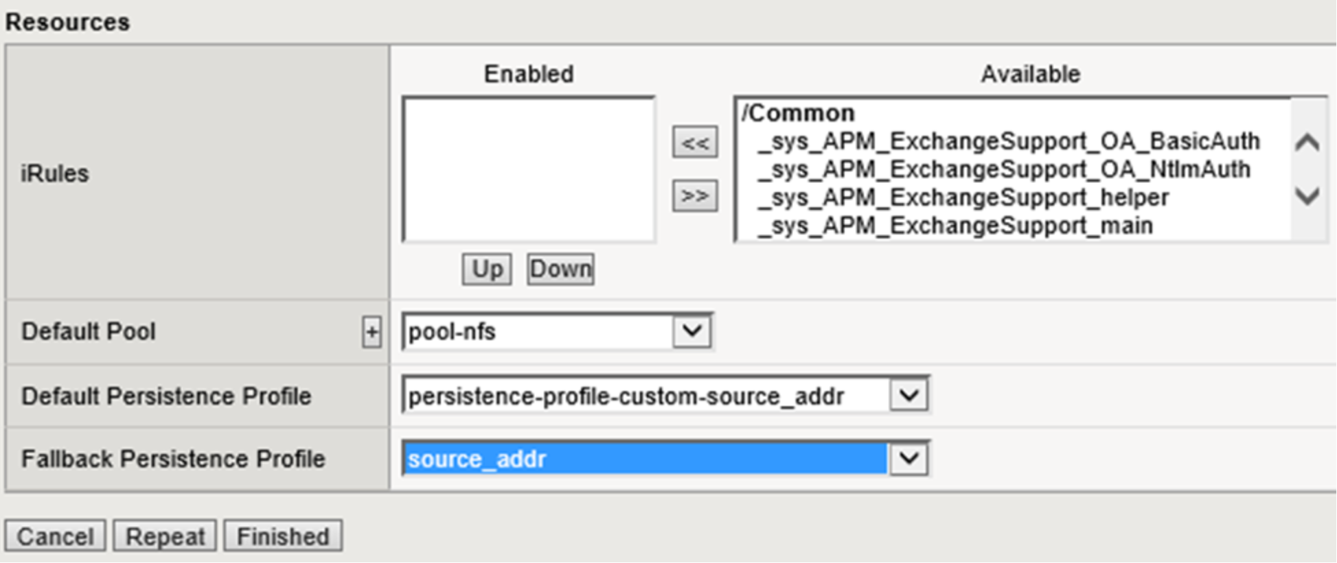
Figure 30. LTM NFS virtual server default pool and persistence profile selection
Regardless of the LTM configuration an ECS NFS export can be mounted directly via any ECS node at either site. This is the beauty of using file-enabled buckets within a federated namespace - a truly global NFS mount point.
Once the NFS monitors, pools, and virtual servers are configured on the LTM at both sites in our example deployment, we can also mount the ECS NFS exports via the LTM virtual server IP addresses. Listed below are a few commands we ran on our client. If the exports are mounted at both sites via the LTM and direct to ECS, performing a listing across the directories will show identical contents as expected.
Below are a few of the mount commands used on the client. The NFS export configured on ECS can be mounted using any of the ECS node IP or virtual server IP addresses or their associated DNS names. Listing the directory contents of all four mounts will reveal the same contents.
sudo mount -o"vers=3" 192.168.101.11:/webapp1/s3_webapp1 ~/f5-101-nfs-via-ecs/ sudo mount -o"vers=3" ecs-2-3.kraft102.net:/webapp1/s3_webapp1 ~/f5-102-nfs-via- ecs/
sudo mount -o"vers=3" f5-ltm-s1-virtual.ecstme.org:/webapp1/s3_webapp1 ~/f5-101- nfs-via-ltm/
sudo mount -o"vers=3" 10.246.150.91:/webapp1/s3_webapp1 ~/f5-102-nfs-via-ltm/
Below is the output from the showmount command. This command shows mount information for an NFS server.
Output of all commands are identical as expected. A single NFS export is created in our federated namespace. That export is available on any node in either of the sites. The export can be mounted by clients using either an ECS node IP address or via the LTM using one of the virtual server IP addresses.
ckraft@kraft-mint18 ~ $ showmount -e ecs-1-1.kraft101.net Export list for ecs-1-1.kraft101.net:
/webapp1/s3_webapp1 *
ckraft@kraft-mint18 ~ $ showmount -e ecs-2-1.kraft102.net Export list for ecs-2-1.kraft102.net:
/webapp1/s3_webapp1 *
ckraft@kraft-mint18 ~ $ showmount -e 10.246.150.90 Export list for 10.246.150.90:
/webapp1/s3_webapp1 *
ckraft@kraft-mint18 ~ $ showmount -e 10.246.150.91 Export list for 10.246.150.91:
/webapp1/s3_webapp1 *
Below is the output from the rpcinfo command. This command is used to report Remote Procedure Call (RPC) information.
Output of both commands are identical as expected. The first query used the IP address of an ECS node and the second query used the IP address of one of the LTM virtual servers.
ckraft@kraft-mint18 ~ $ rpcinfo -p 192.168.101.11
program vers proto port service
100000 4 tcp 111 portmapper
100000 3 tcp 111 portmapper
100000 2 tcp 111 portmapper
100000 4 udp 111 portmapper
100000 3 udp 111 portmapper
100000 2 udp 111 portmapper
100005 3 tcp 2049 mountd
100005 3 udp 2049 mountd
100003 3 tcp 2049 nfs
100024 1 tcp 2049 status
100021 4 tcp 10000 nlockmgr
100021 4 udp 10000 nlockmgr
ckraft@kraft-mint18 ~ $ rpcinfo -p 10.246.150.91
program vers proto port service
100000 4 tcp 111 portmapper
100000 3 tcp 111 portmapper
100000 2 tcp 111 portmapper
100000 4 udp 111 portmapper
100000 3 udp 111 portmapper
100000 2 udp 111 portmapper
100005 3 tcp 2049 mountd
100005 3 udp 2049 mountd
100003 3 tcp 2049 nfs
100024 1 tcp 2049 status
100021 4 tcp 10000 nlockmgr
100021 4 udp 10000 nlockmgr
Example: Geo-affinity via iRule on LTM
Some organizations may find it useful to configure their LTM with access to both local and remote ECS nodes. Applications generally experience the best performance when communicating with a local ECS. For applications that can tolerate additional latencies that come with remote site communication however, ECS can provide increased storage efficiency using XOR.
To take advantage of the storage efficiencies gained on ECS by XOR data must be written evenly across three or more sites. While writing data evenly across multiple sites leads to increased storage efficiency, reading data in a similar fashion may lead to increased WAN overhead and storage inefficiencies due to caching of remote data. This is because for ECS to provide data that is spread out across multiple sites in a strongly consistent manner, it maintains a record of each object’s owner. The object owner is a VDC which serves as the definitive source and ultimate authority for changes to an object. When an object is read from a non-owner site, ECS must communicate with the owner site across the WAN to determine the latest version of the object. By using the LTM to direct applications to the site where an object was originally written, WAN
traffic can be minimized and caching of ECS objects at non-owning sites eliminated or dramatically minimized. This results in higher performance for application workflow and minimal caching of remote data.
Globally balancing writes across ECS sites in a basic round robin fashion will lead to the highest XOR efficiency. However, applying the same basic round robin algorithm to reads would mean requests would most often be sent to a different site to where an object was written. This is where a geo-affinity algorithm is beneficial.
The geo-affinity algorithm provided in this example was validated using the S3 API. It results in the following behavior:
- Equivalent amount of data written to all sites. This leads to lower data protection overhead with XOR.
- Objects are always read from site where it was originally written. This leads to lower WAN traffic, higher performance, and no caching needed for remote data.
As shown in figures below, the rule performs a hash of the object’s path as seen in the URL to determine which pool to send the request to.
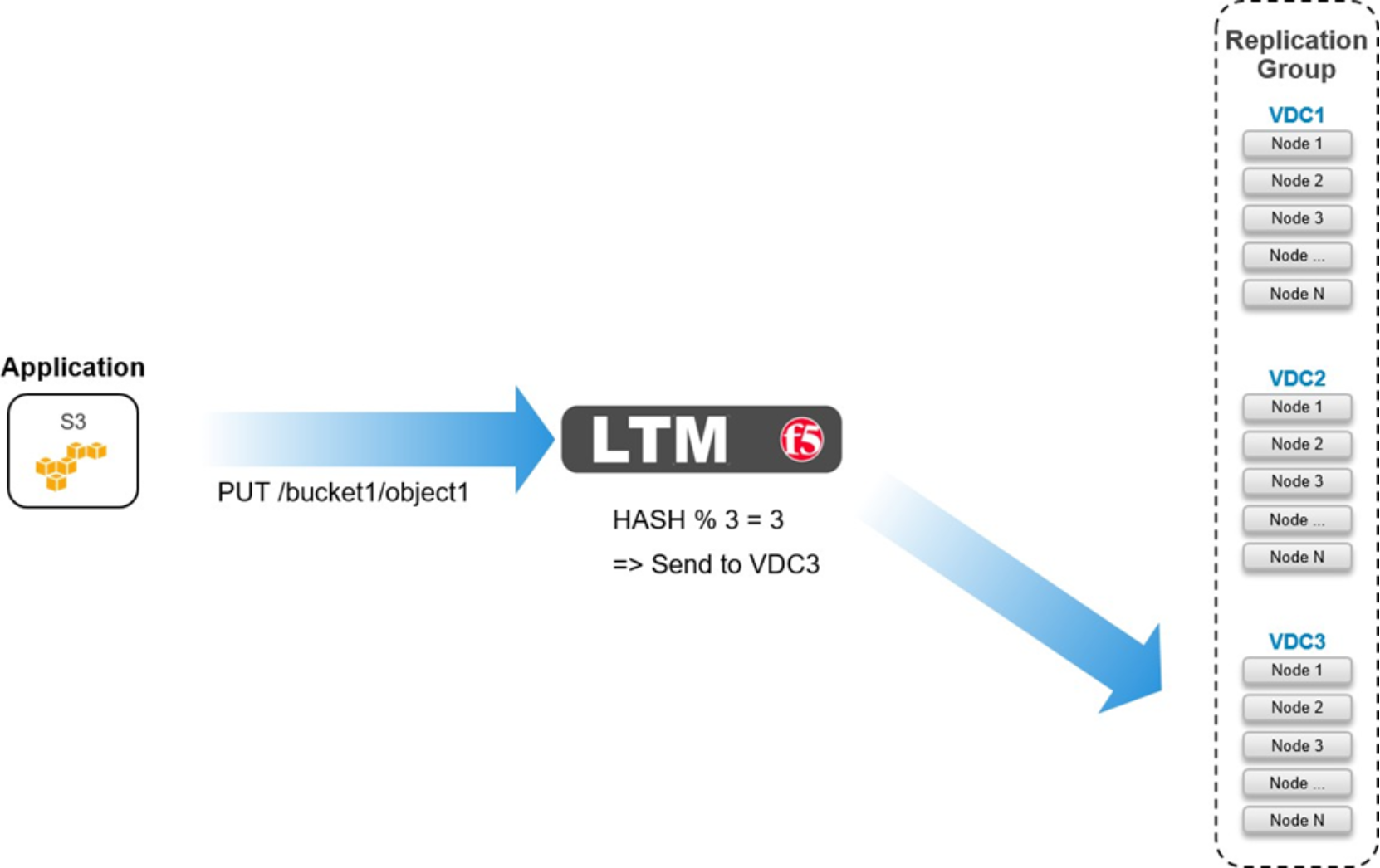
Figure 31. Geo-affinity on LTM for PUT
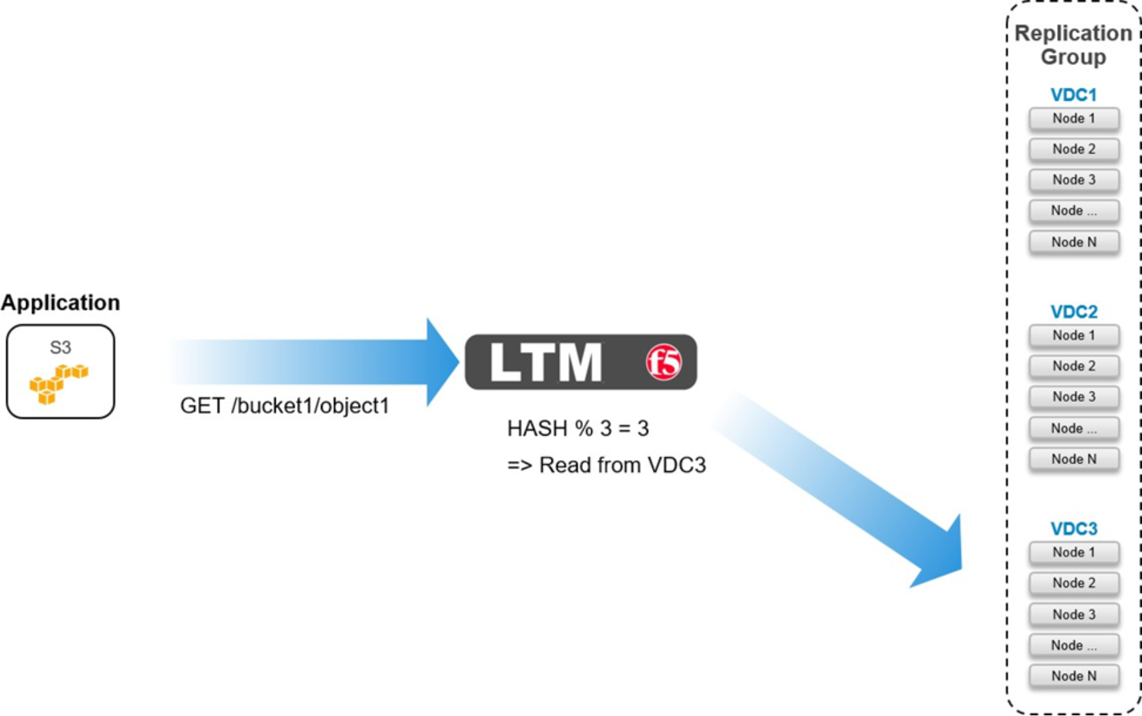
Figure 32. Geo-affinity on LTM for GET
Below is a code sample which shows an iRule configured on an LTM with three pools, one local and two remote to the LTM.
when HTTP_REQUEST {
if { [HTTP::path] ne {/} and [HTTP::path] starts_with {/} }{
if { [getfield [HTTP::host] {:} 1] ends_with ".<my base url>" or [getfield [HTTP::host] {:} 1] ends_with ".s3.amazonaws.com" }{
set path [string range [HTTP::path] 1 end]
}
else {
set pathList [split [HTTP::path] {/}] if { [llength $pathList] > 2 } {
set path [string range [join [lreplace $pathList 1 1] {/}] 1
end]
}
}
if { [info exists path] and $path ne {} } { binary scan [sha1 $path] H6 hash
switch -- [expr 0x$hash % 3 ] {
0 { pool /Common/pl-stor-ecs-vdc1-9020 }
1 { pool /Common/pl-stor-ecs-vdc2-9020 }
2 { pool /Common/pl-stor-ecs-vdc3-9020 }
}
}
}
}
Note: Administrators familiar with URL redirection, or URL forwarding, may consider implementing an iRule to direct clients to send traffic to ECS nodes based on information contained in HTTP requests, such as a bucket name, for example. This may work, however, extensive testing must be taken with each individual application to ensure the iRule works as expected. Simple tests show, at the time of publication, that Boto in Python works with redirects but S3 Browser does not.
Note: The ecs-object-client-java library on GitHub at https://github.com/EMCECS has geo-pinning built in. When an object is written a hash is calculated that allows the READ request to be directed back to the owning site.