
Physical network configuration
Physical network configuration
-
Single-rack networking
Dell EMC servers offer many network adapter options. In the simplified deployment, each server in the rack is connected to:
- A leaf switch with a single network interface of choice (10/25/100 GbE)
- A management switch (typically 1 GbE) for iDRAC connectivity
Leaf switches are connected to spine switches in a resilient manner.
Dell EMC PowerSwitch S5248F-ON
Each S5248F-ON switch provides six 100 GbE uplink ports. The ports enable high-speed connectivity to spine switches or directly to the data center core network infrastructure. They can also be used to extend connectivity to other racks.
The remaining 48 ports of 25 GbE are used for server connectivity. An OpenShift Container Platform cluster with up to 48 server nodes can easily be accommodated using a pair of S5248F-ON switches. Expansion of an OpenShift Container Platform single-rack cluster beyond 48 nodes is managed in one of two ways: add a second S5248F-ON switch or use the S5232F-ON switch.
Dell EMC PowerSwitch S5232F-ON
The S5232F-ON switch also supports ONIE for zero-touch installation of network operating systems. In addition to its use in 100 GbE leaf-spine deployments, the S5232F-ON switch can be used in high-density deployments, using breakout cables, to achieve up to 128 x 10 GbE or 128 x 25 GbE ports.
Resilient networking
The network architecture employs a VLT connection between the two top-of-rack (ToR) switches. In a non-VLT environment, redundancy requires idle equipment, which drives up infrastructure costs and increases risks. In a VLT environment, all paths are active, adding immediate value and throughput while still protecting against hardware failures.
VLT technology allows a server or bridge to uplink a physical trunk into more than one Dell PowerSwitch switch by treating the uplink as one logical trunk. A VLT-connected pair of switches acts as a single switch to a connecting bridge or server. Both links from the bridge network can actively forward and receive traffic. VLT provides a replacement for Spanning Tree Protocol (STP)-based networks by providing both redundancy and full bandwidth utilization using multiple active paths.
The major benefits of VLT technology are:
- Dual control plane for highly available, resilient network services
- Full utilization of the active link aggregation (LAG) interfaces
- Active-active design for seamless operations during maintenance events
The VLTi configuration in this architecture uses two 100 GbE ports from each ToR switch. You can also use 100 GbE ports for high-speed connectivity to spine switches or directly to the data center core network infrastructure. You can also use them to extend connectivity to other racks.
Scaling
You can scale container solutions by adding multiple application and storage nodes. Your solution might contain multiple racks of servers. To create a nonblocking fabric to meet the needs of the microservices data traffic, we used a leaf-spine network.
Leaf-spine overview
The following concepts apply to Layer 2 and Layer 3 leaf-spine topologies:
- Each leaf switch connects to every spine switch in the topology.
- Servers, storage arrays, edge routers, and similar devices always connect to leaf switches, but never to spines.
We used a single leaf switch at the top of each rack. We employed VLT in the spine layer, which allows all connections to be active while also providing fault tolerance. As administrators add racks to the data center, leaf switches are added to each new rack.
The total number of leaf-spine connections is equal to the number of leaf switches multiplied by the number of spine switches. You can increase the bandwidth of the fabric by adding connections between leaves and spines if the spine layer has capacity for the additional connections.
Layer 3 leaf-spine
In a layer 3 leaf-spine network, traffic is routed between leaves and spines. The layer 3-layer 2 boundary is at the leaf switches. Spine switches are never connected to each other in a layer 3 topology. Equal cost multipath routing (ECMP) is used to load-balance traffic across the layer 3 network. Connections within racks from hosts to leaf switches are layer 2. Connections to external networks are made from a pair of edge or border leaves, as shown in the following figure:
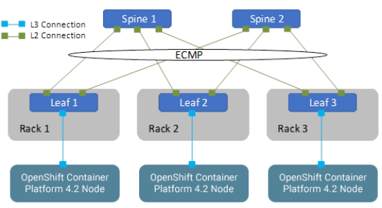
Figure 5. Leaf-spine network configuration
Networking limitation
In our development work, we were unable to deploy bonded multi-NIC configuration of cluster nodes. Two methods can be used to deploy multiple NICs on a cluster node: one method makes use of the ignition control file, and the other requires passing kernel parameters to the Linux kernel that boots each node. Editing the ignition control file is beyond the scope of an automated deployment currently. When we added the NIC bonding parameters to the kernel command line, the nodes entered a continuous boot cycle. To address the difficulties, we used a single leaf switch at the top of each rack. Dell EMC recognizes the importance of bonded multi-NIC support for HA in the network infrastructure. With HA network configuration, each rack has a pair of switches configured with VLTi at the leaf level.
Configuring Dell EMC PowerSwitch switches
This section describes how to configure the PowerSwitch switches that are used for an OpenShift deployment at various scales.
Configuring VLT
The VLT configuration involves the following high-level steps:
- Enable Spanning Tree on the VLT peer switches. Spanning Tree is enabled by default and is recommended to prevent loops in a VLT domain. RPVST+ (the default) and RSTP modes are supported on VLT ports.
- Create a VLT domain and configure the VLT interconnect (VLTi).
- Configure the VLT Priority, VLT MAC Address, and VLT Backup Link.
- Configure the LAG for the connected device.
- Verify and monitor the status of VLT and mismatches by using appropriate OS10 show commands.
Installation with Ansible
Dell EMC Networking modules are supported in Ansible core from Ansible 2.3. You can use these modules to manage and automate Dell EMC switches running OS10. The modules are currently run in local connection mode, using CLI and SSH transport.
For an example of Clos fabric deployment based on Border Gateway Protocol (BGP), see Provision CLOS fabric using Dell EMC Networking Ansible modules example.