
Physical network design
Physical network design
-
Design principles
OpenShift Container Platform 4.10 introduces advanced networking features to enable containers for high performance and monitoring. Dell networking products are designed for ease of use and to enable resilient network creation. Dell Technologies recommends designs that apply the following principles:
- Meet network capacity and the separation requirements of the container pod.
- Configure dual homing of the OpenShift Container Platform node to two Virtual Link Trunked (VLT) switches.
- Create a scalable and resilient network fabric to increase cluster size.
- Allows monitor and trace container communications.
Container network capacity and separation
Container networking takes advantage of the high speed (25/100 GbE) network interfaces of the Dell server portfolio. Also, to meet network capacity requirements, pods can attach to more networks by using available CNI plug-ins.
Additional networks are useful when network traffic isolation is required. Networking applications such as Container Network Functions (CNFs) have control traffic and data traffic. These different types of traffic have different processing, security, and performance requirements.
Pods can be attached to the SR-IOV virtual function (VF) interface on the host system for traffic isolation and to increase I/O performance.
Dual homing
Dual homing means that each node that makes up the OpenShift cluster has at least two NICs, each connected to at least two switches. The switches require VLT connections so that they operate together as a single unit of connectivity to provide redundant data paths for network traffic. The NICs at each node and the ports that they connect to on each of the switches can be aggregated using bonding to assure HA operation.
Network fabric
A nonblocking fabric is required to meet the needs of the microservices data traffic. Dell Technologies recommends deploying a leaf-spine network.
Monitoring and tracing
OpenShift Container Platform 4.10 supports Service Mesh. Users can monitor container traffic by using Kiali and perform end-to-end tracing of applications by using Jaeger.
Resilient networking
Each server that has many NIC options in the rack is connected to:
- Two leaf switches with a network interface of choice: 10 GbE, 25 GbE, or 100 GbE
- A management switch (typically, 1 GbE) for iDRAC connectivity
Our network design employs a VLT connection between the two leaf switches. In a VLT environment, all paths are active; therefore, it is possible to achieve high throughput while still protecting against hardware failures.
VLT technology allows a server to uplink multiple physical trunks into more than one PowerSwitch switch by treating the uplinks as one logical trunk. A VLT-connected pair of switches acts as a single switch to a connecting server. Both links from the bridge network can forward and receive traffic. VLT replaces Spanning Tree Protocol (STP) networks by providing both redundancy and full bandwidth utilization using multiple active paths.
The major benefits of VLT technology are:
- Dual control plane for highly available, resilient network services
- Full utilization of the active link aggregation (LAG) interfaces
- Active/active design for seamless operations during maintenance events
The VLTi configuration in this design uses two 100 GbE ports between each ToR switch. The remaining 100 GbE ports can be used for high-speed connectivity to spine switches, or directly to the data center core network infrastructure.
Scale out with leaf-spine fabric
You can scale container solutions by adding multiple compute nodes and storage nodes. A container cluster can have multiple racks of servers. To create a nonblocking fabric that meets the needs of the microservices data traffic, we used a leaf-spine network.
Leaf-spine overview
Layer 2 and Layer 3 leaf-spine topologies employ the following concepts:
- Each leaf switch connects to every spine switch in the topology.
- Servers, storage arrays, edge routers, and similar devices connect to leaf switches, but never to spines.
Our design used dual leaf switches at the top of each rack. We employed VLT in the spine layer, which allows all connections to be active while also providing fault tolerance. As administrators add racks to the data center, leaf switches are added to each new rack.
The total number of leaf-spine connections is equal to the number of leaf switches multiplied by the number of spine switches. Administrators can increase the bandwidth of the fabric by adding connections between leaf switches and spine switches if the spine layer has capacity for the additional connections.
Layer 3 leaf-spine network
In a Layer 3 leaf-spine network, traffic is routed between leaf switches and spine switches. The boundary between Layer 3 and Layer 2 is at the leaf switches. Spine switches are never connected to each other in a Layer 3 topology. Equal cost multipath routing (ECMP) is used to load-balance traffic across the Layer 3 network. Connections within racks from hosts to leaf switches are Layer 2. Connections to external networks are made from a pair of edge or border leaf switches, as shown in the following figure:
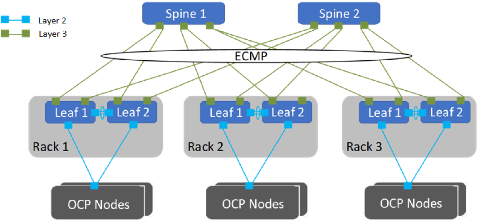
Figure 6. Leaf-spine network configuration
PowerSwitch configuration
Dell’s high-capacity network switches are cost-effective and easy to deploy. The switches provide a clear path to a software-defined data center, offering:
- High density for 25, 40, 50, or 100 GbE deployments in top-of-rack (ToR), middle-of-row, and end-of-row deployments
- A choice of S5048F-ON, S5148F-ON, S5212F-ON, S5224F-ON, S5248F-ON, S5296F-ON, and S5232F-ON 25 GbE and 100 GbE switches; and the S6100-ON
10 GbE, 25 GbE, 40 GbE, 50 GbE, or 100 GbE modular switch - S6100-ON modules that include: 16-port 40 GbE QSFP+; eight-port 100 GbE QSFP28; combo module with four 100 GbE CXP ports and four 100 GbE QSFP28 ports
For our solution design, we used Dell Network Operating System OS10. OS10 allows multilayered disaggregation of network functions that are layered on an open-source Linux-based operating system.
High availability and load balancing
This solution uses the following HA features:
- Red Hat OpenShift Container Platform 4.10: Multiple control-plane nodes and infrastructure nodes
- Resilient load balancing: Two CSAH nodes running HAProxy and KeepAlived
- Dell cloud-native infrastructure: PowerEdge servers with dual NICs
- Dell PowerSwitch: Spine-leaf fabric with VLT
Keepalived
Keepalived is an open-source project that implements routing software using the Virtual Router Redundancy Protocol (VRRP). VRRP enables a switchover to a backup server if the primary server fails. This switchover is achieved by using VIP.
To configure keepalived on both servers:
- Configure one server as “MASTER” with high priority. This will be the primary server.
- Configure the other server as “BACKUP” with lower priority.
Always make external traffic paths highly available to create a complete solution. The cluster administrator can use an external L4 load-balancer in a highly available manner or deploy HAProxy in resilient mode. Deploying a resilient HAProxy requires one additional server. As shown in the following figure, the components of a highly available load-balancer design using HAProxy are:
- Keepalived and HAProxy running on CSAH
- Keepalived and HAProxy running on an additional server
For both components, configure VIP on a suitable network interface.
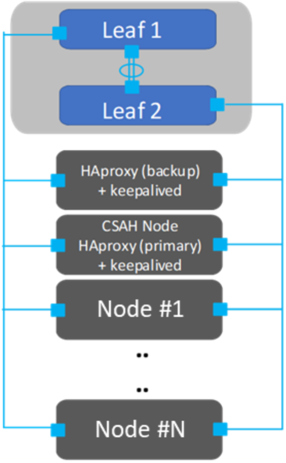
Figure 7. Highly available load balancing