
Validated hardware configuration options
Validated hardware configuration options
-
Introduction
For validation tests in our laboratories, we used various server configurations for the Ready Stack for OpenShift Container Platform 4.3. Dell Technologies recommends selecting server configurations that are known to provide a satisfactory deployment experience and to meet or exceed Day-2 operating experience expectations. This section provides guidelines for Intel microprocessor selection, memory configuration, local (on-server) disk storage, and network configuration.
Selecting the server processors
The Intel Xeon Gold processor family provides performance, advanced reliability, and hardware-enhanced security for demanding compute, network, and storage workloads.
For clusters of 30 or more nodes, Dell Technologies recommends Intel Xeon Gold series CPUs in the range of the 6226 to 6252 models. This selection is based on experience that we gained from deployment and operation of OpenShift Container Platform 4.3 running on PowerEdge R640 and R740xd servers. The design information in this guide is based on clusters of servers with either Intel Gold 6240 or Intel Gold 6238 processors.
Dell Technologies realizes that many sites prefer to use a single-server configuration for all node types. However, this option is not always cost-effective, nor is it always practical.
When selecting a processor, consider the following recommendations:
- Processor core count—The processor core count must be adequate to ensure satisfactory performance of the workload operations and base services that are running on each node.
- Thermal design power (TDP)—The CPU must be able to accommodate the amount of heat that needs to be removed from the server through the heat sinks and cooling air flow.
- Ability to dissipate heat—During validation work with high-core-count, high-TDP processors, the thermal delta (air discharge temperature minus air intake temperature) across a server was recorded at 65°F. Excessive air discharge (egress) temperature from the server might lead to a premature server-component or system failure.
- The design of compute (worker) nodes for use as part of your OpenShift Container Platform cluster can implement many compute node configurations. Worker nodes can use Intel or AMD-based CPU platforms. The processor architecture and core count per node selection can have significantly affect the acquisition and operating cost of the cluster that is needed to run your organization’s application workload.
When ordering and configuring your PowerEdge servers, see the Dell EMC PowerEdge R640 Technical Guide and Dell EMC PowerEdge R740 and R740xd Technical Guide.
For CPU information, see Intel Xeon Gold Processors.
Per-node memory configuration
The Dell Technologies engineering team designated 192 GB, 384 GB, or 768 GB of RAM as the best choice based on memory usage, DIMM module capacity for the current cost, and likely obsolescence over a five-year server life cycle. We chose a midrange memory configuration of 384 GB RAM to ensure that the memory for each CPU has multiples of three banks of DIMM slots populated to ensure maximum memory-access cycle speed. You can alter the memory configuration to meet your budgetary constraints and operating needs.
Also, consult OpenShift architectural guidance and consider your own observations from running your workloads on OpenShift Container Platform 4.3. For guidance about server memory population (location of DIMM modules in DIMM slots), particularly the use of the firmware setting for “Performance Optimized” mode, see the following Dell Technologies Knowledge Base article: Dell EMC PowerEdge–14G Memory Population Rules updated for certain server's configurations.
Disk drive capacities
The performance of disk drives significantly limits the performance of many aspects of OpenShift cluster deployment and operation. We validated deployment and operation of OpenShift Container Platform using magnetic storage drives (spinners), SATA SSD drives, SAS SSD drives, and NVMe SSD drives.
Our selection of all NVMe SSD drives was based on a comparison of cost per GB of capacity divided by observed performance criteria such as deployment time for the cluster and application deployment characteristics and performance. While there are no universal guidelines, over time users gain insight into the capacities that best enable them to meet their requirements. Optionally, you can deploy the cluster with only HDD disk drives. This configuration has been shown in testing to have many adverse performance consequences.
Network controllers and switches
When selecting the switches to include in the OpenShift Container Platform cluster infrastructure, consider the overall balance of I/O pathways within server nodes, the network switches, and the NICs for your cluster. When you choose to include high-I/O bandwidth drives as part of your platform, consider your choice of network switches and NICs so that adequate network I/O is available to support high-speed, low-latency drives:
- HDD drives—These drives have lower throughput per drive. You can use 10 GbE for this configuration.
- SATA/SAS SSD drives—These drives have high I/O capability. SATA SSD drives operate at approximately four times the I/O level of a spinning HDD. SAS SSDs operate at up to 10 times the I/O level of a spinning HDD. With SSD drives, configure your servers with 25 GbE.
- NVMe SSD drives—These drives have high I/O capability, up to three times the I/O rate of SAS SSDs. We populated each node with 4 x 25 GbE NICs, or 2x 100 GbE NICS, to provide optimal I/O bandwidth.
The following table provides information about selecting NICs to ensure adequate I/O bandwidth and to take advantage of available disk I/O:
Table 9. NIC selection to optimize I/O bandwidth
NIC selection
Worker node storage device type
2 x 25 GbE
Spinning magnetic media (HDD)
2 x 25 GbE or 4 x 25 GbE
SATA or SAS SSD drives
4 x 25 GbE or 2 x 100 GbE
NVMe SSD drives
True network HA fail-safe design requires that each NIC is duplicated, permitting a pair of ports to be split across two physically separated switches. A pair of PowerSwitch S5248F-ON switches provides 96 x 25 GbE ports, enough for a total of approximately 20 servers. This switch is cost-effective for a compact cluster. While you can add another pair of S5248F-ON switches to scale the cluster to a full rack, consider using PowerSwitch S5232F-ON switches for a larger cluster.
The PowerSwitch S5232F-ON provides 32 x 100 GbE ports. When used with a four-way QSFP28 to SFP28, a pair of the switches provides up to 256 x 25 GbE endpoints, more than enough for a rackful of servers in the cluster before more complex network topologies are required.
Low latency in an NFV environment
NFV-centric data centers require low latency in all aspects of container ecosystem design for application deployment. This requirement means that you must give attention to selecting low-latency components throughout the OpenShift cluster. We strongly recommend using only NVMe drives, NFV-centric versions of Intel CPUs, and, at a minimum, the PowerSwitch S5232F-ON switch. Consult the Dell Technologies Service Provider support team for specific guidance.
Power configuration
Dell Technologies strongly recommends that all servers are equipped with redundant power supplies and that power cabling provides redundant power to the servers. Configure each rack with pairs of power distribution units (PDUs). For consistency, connect all right-most power supply units (PSUs) to a right-side PDU and all left-most PSUs to a left-side PDU. Use as many PDUs as you need, in pairs. Each PDU must have an independent connection to the data center power bus.
Figure 7 shows an example of the power configuration that is designed to assure redundant power supply to each cluster device.
Storage configuration
Consult the PowerMax 2000 or 8000 Guide or Isilon H500 guides for detailed cabling with appropriate Fibre Channel cables and for operations and management of the storage arrays.
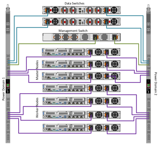
Figure 7. PSU to PDU power template
Note: This diagram is for reference only and does not depict the storage arrays that were configured.