
None
None
-
Overview
Deploying PostgreSQL on-premises with PowerFlex as the software defined storage, offers organizations a self-hosted solution for managing their databases while supplying a robust and reliable solution for managing their data. PostgreSQL provides customers complete control over their data and infrastructure. PostgreSQL also enables the customer to use existing supported hardware and storage resources, optimizing cost-efficiency, and performance.
Logical architecture
The following figure describes the logical architecture of PostgreSQL database that is deployed on Dell PowerFlex 4.0 with a two-layer deployment architecture:
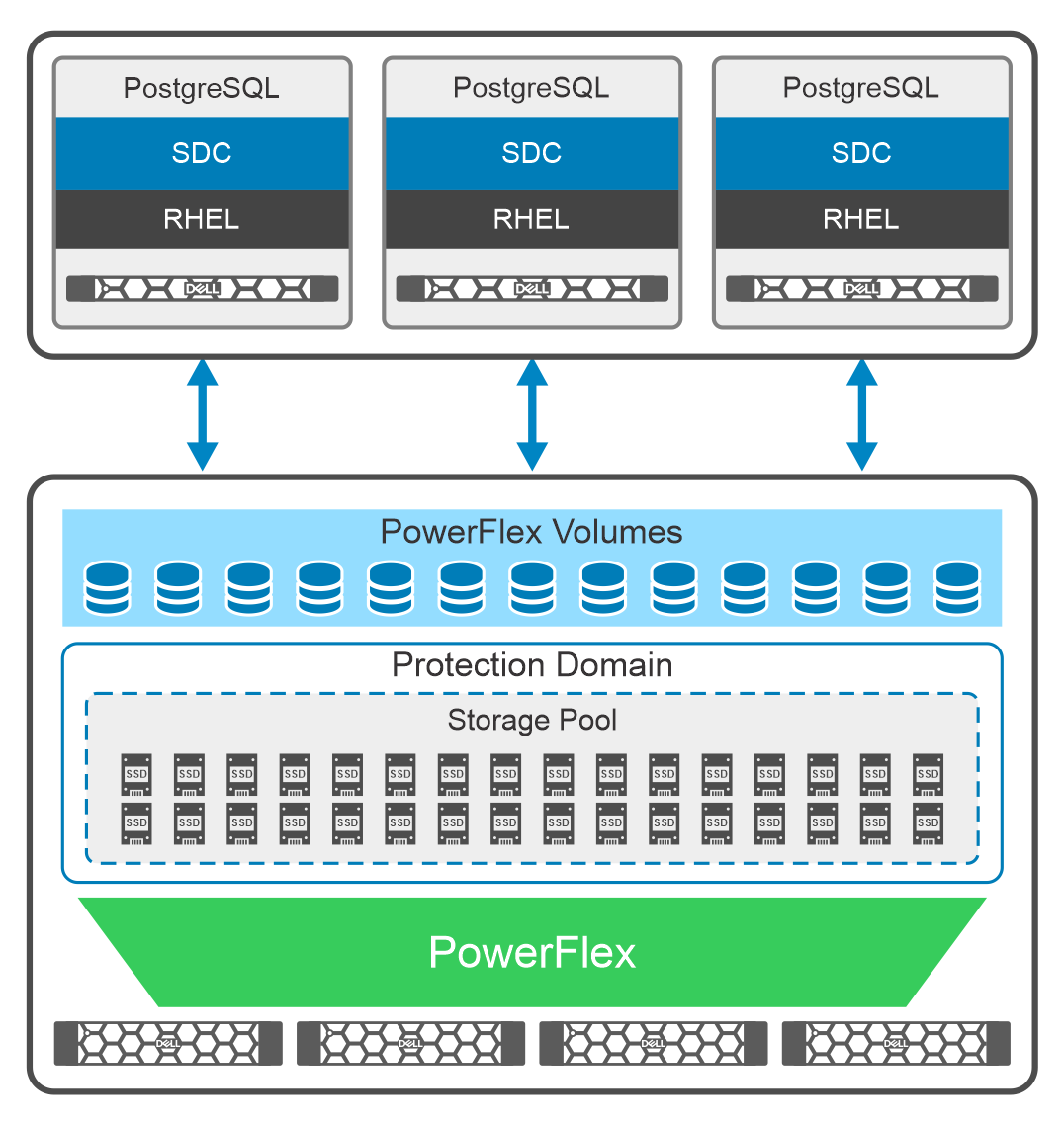
Figure 6. Logical architecture: PostgreSQL on PowerFlex two-layer deployment
PowerFlex deployment is configured as a two-layer architecture with a single PowerFlex protection domain that consists of four SDSs, and one storage pool within the protection domain. The PostgreSQL database volumes are created from this storage pool.
Four PowerFlex R750 servers, each with SAS SSDs disks, are used as storage only nodes. The PowerFlex SDS components are installed on each of these servers which contribute to the PowerFlex storage pool. These SAS disks provide an aggregated storage pool capacity of 26 TB within a single protection domain.
In the on-premises lab environment, three PowerFlex R650 servers in bare metal configuration are used as compute only nodes with Red Hat Enterprise Linux operating system. The PowerFlex SDC component is installed on each of these servers and provides access to the volumes created in the storage pool. The PostgreSQL databases are then deployed on these servers using the PowerFlex volumes.
For more information about the software and hardware that is used in the lab tests, see PowerFlex Node specifications.
Note: Many best practices described in this paper, also apply to the virtualized, and container-based PostgreSQL deployments with PowerFlex.
Network architecture
The following diagram shows the network architecture of this solution:
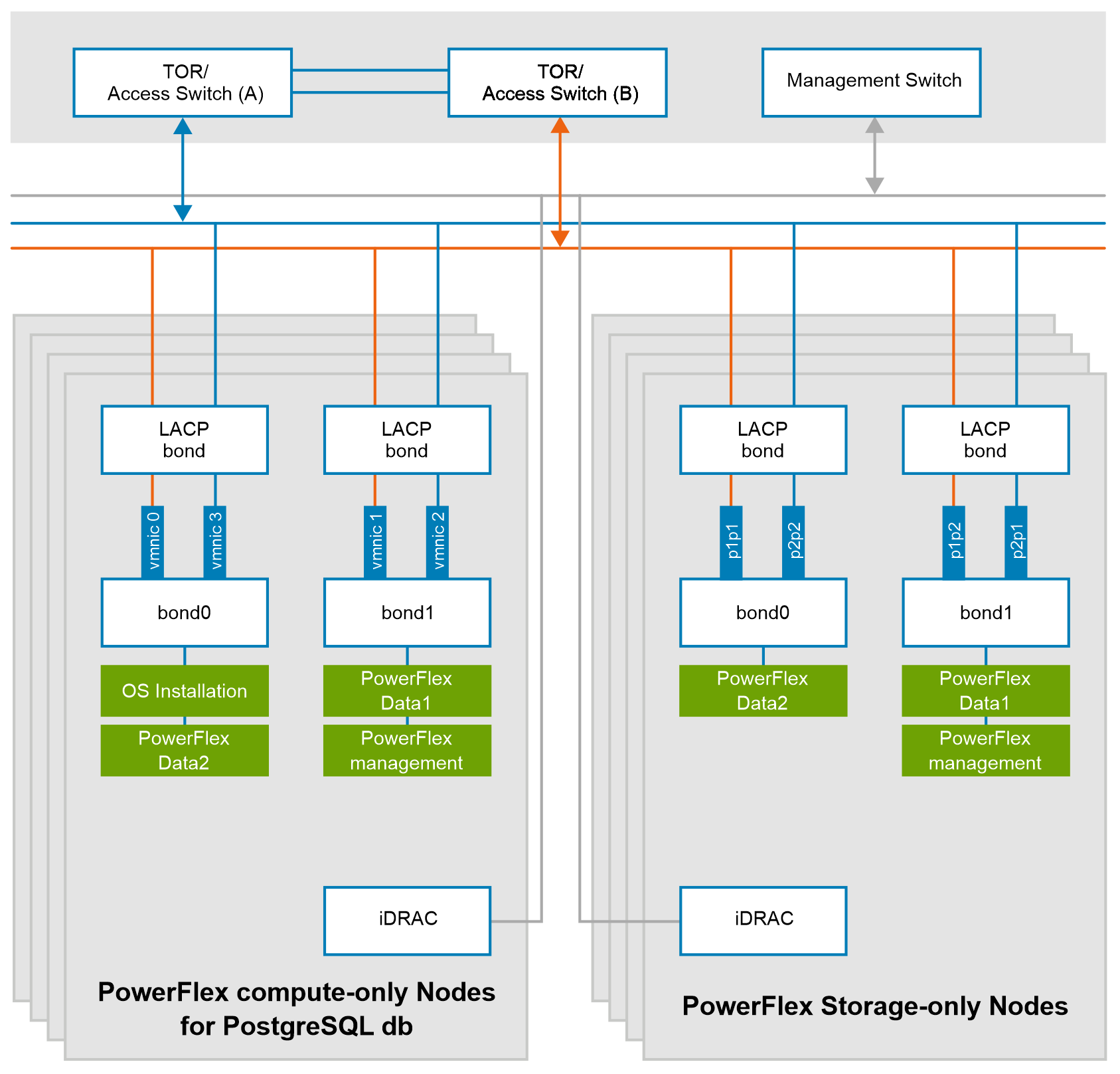
Figure 7. Network design of PowerFlex nodes
At the physical layer, two supported Top of Rack (TOR) switches are used for redundancy and load-balancing purpose. A peer link is configured on both the TOR switches.
The network ports of different network interfaces on each PowerFlex node are configured to carry PowerFlex management and PowerFlex data traffic. An LACP bond is configured at the host level with two network interfaces to form a single-bonded (logical) interface for increased bandwidth and redundancy.
The bond0 and bond1 are the LACP bonded interfaces and are configured with multiple VLAN tagged interfaces for all the PowerFlex networks. The traffic is logically separated by creating VLANs which segregates different traffic on the bond interfaces as shown in the preceding figure.