
None
None
-
The following diagram shows the logical architecture of the containerized SQL Server instances that is deployed on eight PowerFlex hyperconverged nodes with Red Hat OpenShift cluster. It also illustrates the OpenShift cluster that has three control planes and eight worker nodes. Same PowerFlex cluster nodes are acting as worker nodes in the setup. There are three deployments that are involved in this architecture:
- PowerFlex deployment
- OpenShift Cluster deployment
- SQL Server pod/container deployment
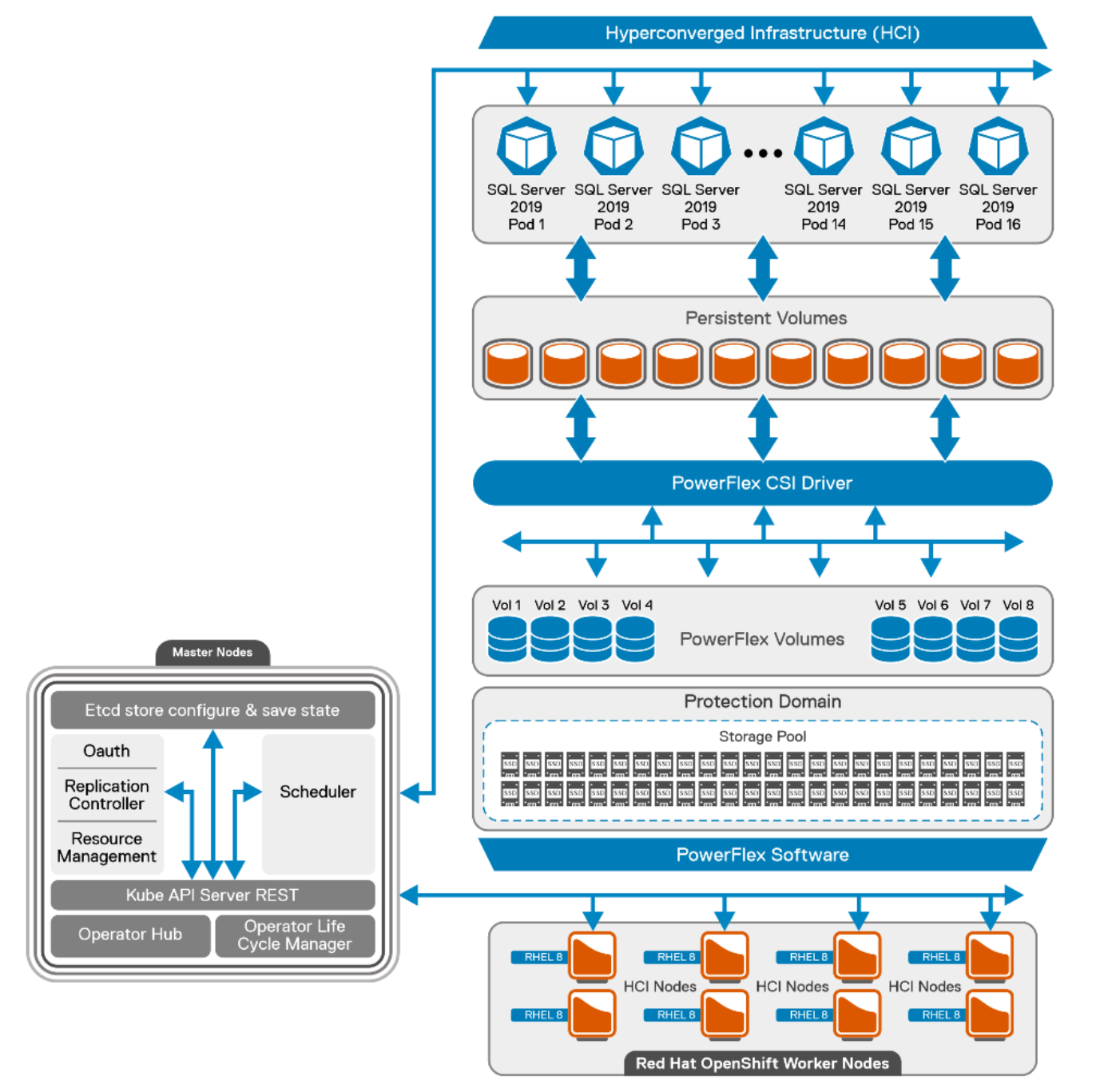
Figure 2. Logical architecture of SQL Server 2019 with OpenShift containers
PowerFlex deployment
The PowerFlex cluster is built from eight bare-metal nodes that are configured in the hyperconverged deployment model. PowerFlex cluster leverages its storage data server (SDS) component to provide resilient storage layout.
Each node is populated with ten solid state drives (SSDs) of size 960 GB. These total 64 disks from eight nodes are aggregated to make one resilient storage pool and the usable storage volumes are carved out as required. SDSs are optimized for rebuild, rebalance, and I/O parallelism. The user data layout among SDS components is managed through storage pools, protection domains, and Volumes. PowerFlex storage layout for this reference architecture is as follows:
- Single Protection Domain (domain 1) is allocated from the SSDs in the eight PowerFlex nodes.
- Single Storage pool (SP-SSD-1) is created on a new protection domain and then persistent client volumes are created from this Storage Pool.
All the SQL Server pod volumes are provisioned by the PowerFlex software from the storage pool as requested by the PowerFlex CSI driver. For more information about PowerFlex recommendations, see PowerFlex Best Practices.
For more information about the configuration of PowerFlex nodes and VM configuration, see Appendix Configuration details.
OpenShift cluster deployment
This section outlines the basic constructs of an OCP deployment on PowerFlex family.
The OpenShift cluster contains the following important elements:
- Helper node
- Bootstrap node
- Control plane node
- Worker node
Helper node
The Helper node is the intermediate host that helps to deploy and manage the OCP cluster. It is a Linux host with OpenShift binaries that are installed to deploy and manage the cluster. In this guide, the helper node is seen as the service node and is deployed on to a separate VM.
All CLI-based commands are run from the service node. This guide uses Red Hat Enterprise Linux 8 minimal ISO for operating system installation. The service node is configured to host the OpenShift installation binaries and to generate the ignition file to deploy all the nodes of the cluster.
Bootstrap node
The bootstrap node is the first node to be booted to the custom ISO. The purpose of the bootstrap node is to configure the control plane and install the control plane components on the active nodes. This configuration is achieved by creating a temporary OCP cluster for deploying the control plane API and the control plane nodes. Once the master nodes are up and the bootstrapping process is complete, the bootstrap node is used for the OCP installation process. In this architecture, the bootstrap node is deployed on the VM.
Control plane nodes
Control plane nodes create, schedule, and manage all aspects of the OCP cluster. control plane nodes can be configured to allow for pods to be scheduled on them, that is, for them to serve as worker nodes. This solution does not schedule workloads on control planes. The following is a list of the other main services that the control plane nodes are needed for:
- API interface
- Authentication or authorization
- Container scheduling
- Controller management
- Configuration database and etcd
Kubernetes manages the containers using a declarative model where the required state of the cluster is maintained. The control plane (Master nodes/API) continuously monitors the state. Controllers check for the current and the required state in loops. When a configuration change is detected, the control plane responds by updating the state of the resource. For example, to change any kubelet on OpenShift nodes a machine configuration YAML resource file is applied to the cluster. Once the control plane realizes that the required state of the nodes no longer matches the running state, it corrects the state by implementing the change that is applied using the machine configuration file.
Three control plane nodes are hosted on separate VMs to avoid using the resources from the PowerFlex HCI nodes. Red Hat Enterprise Linux Core operating system (RHCOS) is the default operating system on all the control plane machines.
Worker nodes
In the OpenShift Container Platform 4.9, you have the option of using the Red Hat Enterprise Linux (RHEL) machines as a compute machine that is also known as worker machines, in a user-provisioned infrastructure installation method of cluster deployment.
This reference architecture uses the PowerFlex HCI nodes as worker nodes that are deployed with the Red Hat Enterprise Linux operating system. Eight worker nodes are used to host the SQL Server 2019 workload.
Following are some of the pre-requisites before adding the Red Hat Enterprise Linux based compute or worker nodes to the cluster:
- Must have a valid OpenShift container platform subscription with the Red Hat account.
- Base operating system on the worker nodes should be RHEL 8.4.
- Separate RHEL 7 machine is required to run an Ansible playbook and add the worker node to the cluster.
- Must have OpenShift CLI installed on the RHEL 7 machine.
- Ensure that the RHEL 7 machine can access all the worker nodes and the helper nodes.
- Enable the password less SSH to all the worker nodes and the helper node.
For more information about adding an RHEL worker node in the OCP, see adding RHEL compute nodes to a cluster.
This reference architecture follows the user-provisioned method of cluster deployment. Every node, component is deployed manually by the user and not with the installer based provisioned installer. The following table shows the different nodes that are deployed in the cluster:
Table 2. OpenShift cluster node details
Name
Status
Roles
node1.hci
Ready
worker
node2.hci
Ready
worker
node3.hci.lab
Ready
worker
node4.hci
Ready
worker
node5.hci
Ready
worker
node6.hci
Ready
worker
node7.hci
Ready
worker
node8.hci
Ready
worker
ocp-cp-1.lab.ocp.lan
Ready
control plane
ocp-cp-2.lab.ocp.lan
Ready
control plane
ocp-cp-3.lab.ocp.lan
Ready
control plane
Note: For more information about the configuration of OpenShift nodes and VM configuration, see Appendix Configuration details
PowerFlex CSI deployment
The PowerFlex CSI driver is used to provide persistent storage to OCP through the PowerFlex storage system. The CSI driver installs the custom resource definition (CRD) in the storage.dell.com API group and requires a few input parameters to be provided such as: the PowerFlex end point (gateway details) and the system name to connect to the PowerFlex cluster. A secret key is created in the namespace to connect to the end point. This secret key stores the credentials to connect to the PowerFlex cluster. Upon successful deployment of the CRD.
The following table shows the storage controller and CSI pods that are deployed in the cluster:
Table 3. Controller and CSI pod details
Name
Status
Node
vxflexos-controller-5759bc87c5-gwm7w
Running
node5.hci
vxflexos-node-4m4fx
Running
node5.hci
vxflexos-node-9w56f
Running
node2.hci
vxflexos-node-cs6d8
Running
node7.hci
vxflexos-node-l7kjj
Running
node4.hci
vxflexos-node-ndqcn
Running
node8.hci
vxflexos-node-qzlzg
Running
node3.hci
vxflexos-node-w59wf
Running
node6.hci
Each CSI pod facilitates the storage provisioning and the file system creation on the worker nodes. CSI uses the storage classes to dynamically provision the volumes. A storage class is an object that describes the policy for the quality-of-service levels. These policies define the provisioner reclaim policy and driver details. The PowerFlex CSI provides YAML files to deploy the storage classes. EXT4 and XFS are the two standard storage class templates by PowerFlex CSI. It is recommended by Microsoft to use XFS for database volumes. Hence, the XFS storage class is deployed to provision the volumes with the XFS file system.
Table 4. CSI storage class
Name
Provisioner
Reclaim
policy
Volume
binding mode
Allow volume expansion
Age
vxflexos-xfs
csi-vxflexos.dellemc.com
Delete
Immediate
true
102d
The CSI driver for Dell PowerFlex can be deployed by using the provided Helm v3 charts and installation scripts on both Kubernetes and OpenShift platforms. For more information about the PowerFlex CSI installation using Helm charts, see PowerFlex CSI Documentation.
SQL Server pod/container deployment
This reference architecture deploys the SQL Server as a stateful application. SQL pods are deployed across eight worker nodes. Each node hosts two SQL Server pods. Each pod is hosting a single container image of the SQL Server 2019 instances and the data is stored on the persistent volume provisioned by the PowerFlex CSI plug-in. The controller verifies if the current state matches the wanted deployment state, and creates a ReplicaSet if necessary, and then creates the pods.
The following table shows the deployment of the SQL server pods on the OCP cluster:
Note: The names may be different in your environment.
Table 5. SQL Server pod details
Name
Status
Node
sql1-58b97fb88f-jw54v
Running
node1.hci
sql10-778d847d7-k78lq
Running
node3.hci
sql13-7b4cc476f4-fgm2s
Running
node4.hci
sql14-5dc4d4c65b-lnlst
Running
node4.hci
sql17-8d6d7fbf5-8prqh
Running
node5.hci
sql18-6b8c59645c-bz9r9
Running
node5.hci
sql2-6d7b874595-mbsjh
Running
node1.hci
sql21-7bdd69cbbb-dnmh8
Running
node6.hci
sql22-f55796588-l66r9
Running
node6.hci
sql25-7bdbc6576c-grll7
Running
node7.hci
sql26-78d5bd4777-kz9cv
Running
node7.hci
sql29-7796c56476-fbprb
Running
node8.hci
sql30-6f87df878d-qjsqz
Running
node8.hci
sql5-77c4cfd88d-x7gsv
Running
node2.hci
sql6-694d44bcf8-nstkx
Running
node2.hci
sql9-85f87548d7-7ks5k
Running
node3.hci
SQL server ConfigMap
This solution uses the ConfigMap object to pass the SQL Server startup parameters. This ConfigMap file provides a few important parameters for each SQL Server pod. It defines the default data and log directory path to the pod. This is an important Kubernetes object used to pass the required information to the application deployed.
The ConfigMap is like the secret key, but it is designed to support working more conveniently with strings that do not contain sensitive information.
SQL server pod database layout
To get an optimal database performance it is a good practice to design the database layout. The SQL Server Database files are mostly categorized as random and sequential files. Storing all the files in one partition/drive is a sign of bad database design. To fully use the SDS storage pool capacity and I/O performance, database and log files are separated across different volumes for better I/O throughput.
The following figure shows the SQL server pod database layout. The layout includes database files; transaction log files and temp files distributed across different volumes.
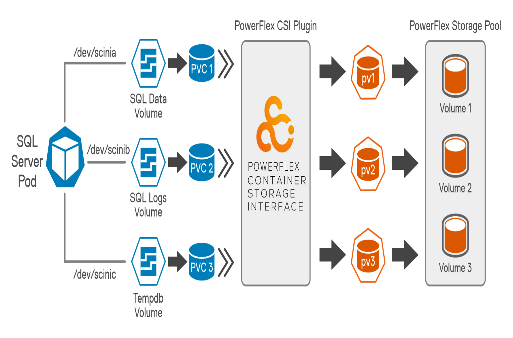
Figure 3. SQL server Pod database layout
As a best practice, The TempDB files are moved from their default location to another persistent volume to optimize the database performance. Preallocating space for TempDB and assigning a large file size accommodates most typical workloads and results in optimized performance. Also, increasing the number of tempdb files reduces the database contention. This reference architecture recommends configuring 16 tempdb files to improve the database performance.
The following table shows both the volume size and file systems used for this solution to store a sample database:
Table 6. Pod storage details
Volume name
Size
File system
Purpose
/dev/scinia
304 GB
xfs
SQL data volume to store datafiles
/dev/scinib
200 GB
xfs
SQL log volume to store database transaction log files
/dev/scinic
304 GB
xfs
SQL temp volume to store tempdb files