
None
None
-
The following diagram shows the network architecture of this solution.
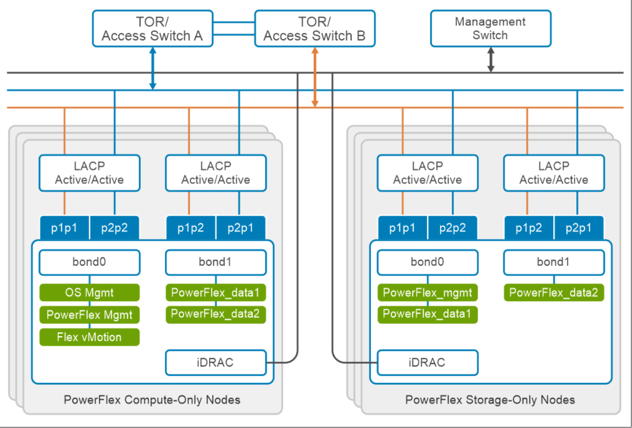
Figure 6. Network design of Delphix DevOps appliance with Dell PowerFlex
At the physical layer, two Top of Rack (TOR) switches are used for redundancy and load-balancing purposes at each site. A peer link is configured on both the TOR switches.
The network ports of different network interfaces on each PowerFlex nodes are configured to carry PowerFlex management, PowerFlex data1, and PowerFlex data2. An LACP bond is configured at the host level with two network interfaces to form a single-bonded (logical) interface for increased bandwidth and redundancy.
The bond0 and bond1 are the LACP bonded interfaces and are configured with multiple VLAN tagged interfaces for all the PowerFlex networks. The traffic is logically separated by creating VLANs which separate different traffic on the bond interfaces as shown in the preceding figure. PowerFlex data1 and data2 are used for data traffic.
The Delphix DevOps appliance uses the operating system management network to communicate between the Delphix engine, source, staging, and target environments.
The following table shows the different networks that are configured for this solution. For more information, see the Dell PowerFlex Appliance with PowerFlex 4.x Network Planning Guide | Dell US.
Table 1. Network details
Network type
VLAN ID
OS management
105
PowerFlex management
150
PowerFlex Data 1
151
PowerFlex Data 2
152
vMotion
106