
None
None
-
PowerFlex deployment is performed in a two-layer architecture with the help of PowerFlex Manager that automates the whole process. The Compute Only (CO) nodes of PowerFlex have ESXi 7.0.3 hypervisor installed on them while the Storage Only (SO) Nodes are built on an embedded operating system. Each of the SO Nodes is populated with ten 894 GB SAS SSD drives. For more information about specifications of the PowerFlex nodes, see PowerFlex Node specifications.
After the PowerFlex Manager deploys PowerFlex, a single PowerFlex Protection Domain is created that consists of four SDSs, and then one Storage Pool is created from the SSDs that has 40 physical storage devices within the PD. Two PowerFlex volumes of 3 TB each are created out from this storage pool. The PowerFlex client software (SDC) on each ESXi host then accesses the volumes created in the storage pool. The volumes created in PowerFlex are mapped to all the SDC’s that are used to create the datastores.
The following figures show a sample PowerFlex dashboard and resource information.
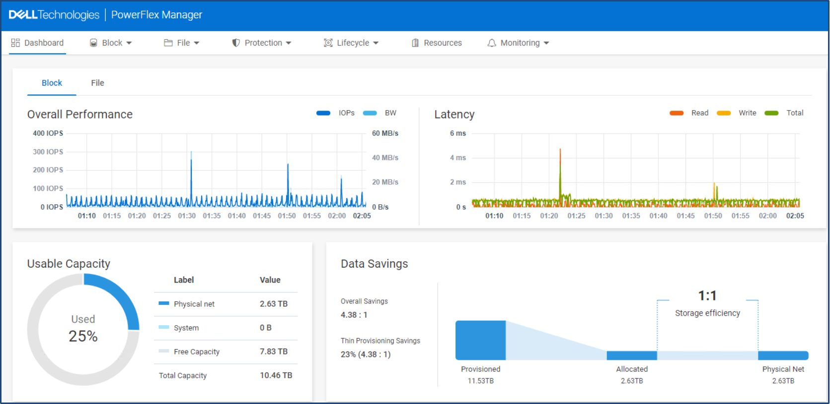
Figure 9. PowerFlex 4.0 dashboard
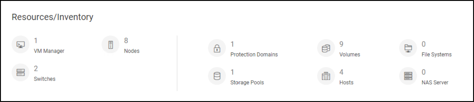
Figure 10. PowerFlex 4.0 Resources/Inventory information
The following figure shows the overall logical architecture of this solution.
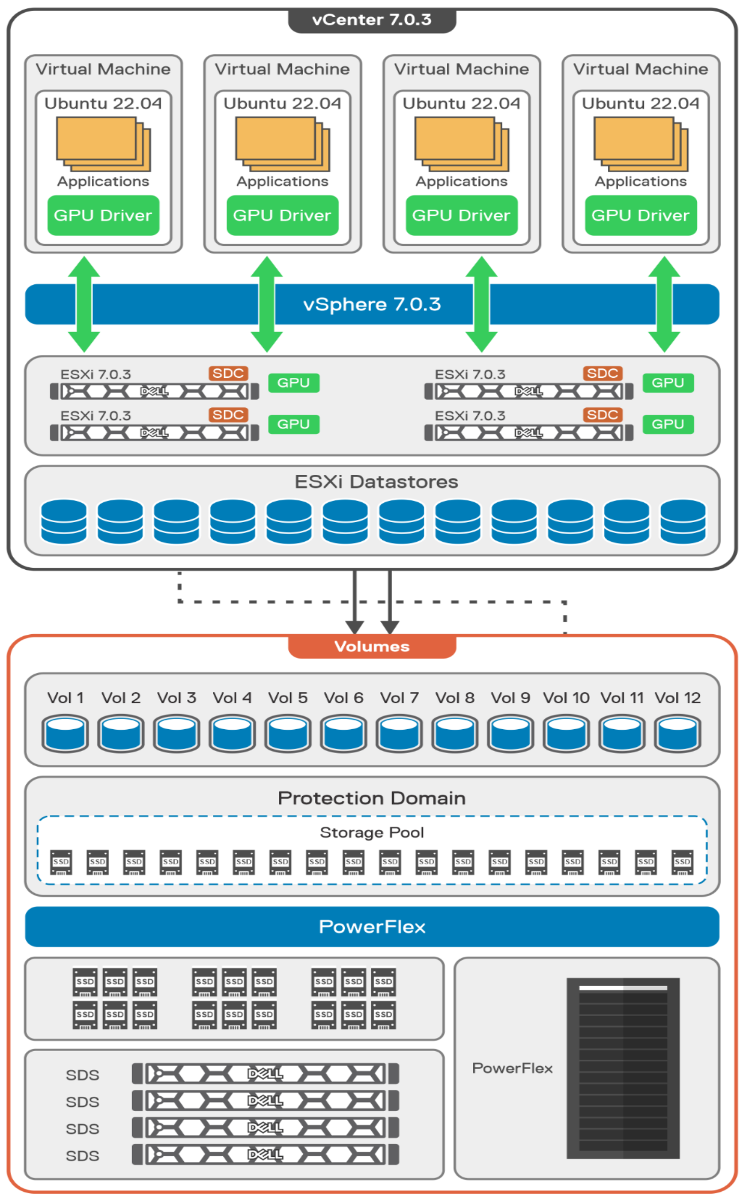
Figure 11. Logical architecture
On the client side, there are four ESXi hosts that are managed by vCenter 7.0.3. Each of these CO nodes contain a single A100 GPU. Four VMs are then created and reside on each of the ESXi hosts. A vGPU profile of grid_a100-7-40c is configured for each VM. The VMs have Ubuntu 22.04 operating system installed. For more information about the configuration of the VMs, see VM Configuration.