
Disk Processor Enclosure (DPE) – 480/F, 680/F, 880/F
Disk Processor Enclosure (DPE) – 480/F, 680/F, 880/F
-
Dell Unity’s Disk Processor Enclosure (DPE) for Unity XT Series models use a 25-drive 2U DPE using 2.5” drives. Note, though, that the Unity XT 480/F, 680/F, and 880/F models use a different physical chassis than the 380/F. The following figures and related information are specific to 480/F, 680/F, and 880/F models. For information about the DPE for the 380/F model, see the section Disk Processor Enclosure (DPE) – 380/F.
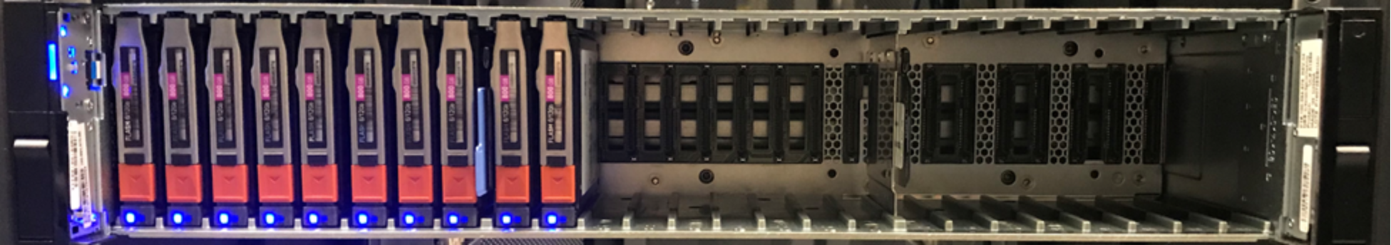
Figure 10. 25-Drive 2U DPE (480/F, 680/F, 880/F)
For 480/F, 680/F, and 880/F systems, on the front of the DPEs (see Figure 10) are LEDs for both the enclosure and drives to indicate status and faults. The first four drives of the DPE are known as system drives, and contain data used by the operating environment. While they can be used in Pools to hold user data, the entire formatted capacity of the system drives will not be available as some space is reserved for the system. These drives should not be moved within the DPE or relocated to another enclosure and should be replaced immediately in the event of a fault. A system drive cannot be used as a traditional pool hot spare for a non-system drive. For this reason, the minimum number of drives in a system is 5 with system drives configured in a RAID 1/0 (1+1 or 2+2) configuration including a non-system drive traditional pool hot spare.
The rear of the DPE reveals the Storage Processors (SP) and their connectivity options (see Figure 11). Each SP has 1x 1GbE management port, 1x 1GbE service port, 1x 4-port mezzanine card (optional), 2x I/O module slots (optional), and 2x 12Gb SAS ports, used for connecting additional storage and each SAS port has a 4-lane configuration. For management and service, each SP has a dedicated 1GbE BaseT management port and a dedicated 1GbE BaseT service port; both ports can operate at 1Gb/100Mb/10Mb speeds. In Dell Unity OE version 5.1, management port settings can be customized to match the environment by manually changing MTU, port speed and/or duplex settings. The range of these settings include MTU of 1280 through 9000, port speeds of 1Gbps, 100Mbps, or 10Mbps, and advertised duplex of full, half, or auto. These settings can be changed using svc_network service command. For front-end connectivity, the SPs have the option of a 4-port mezzanine card which have the option of being a 4-port 25GbE Optical, 4-port 10GbE BaseT, or blank filler based on how the system is ordered. For the 4-port 25GbE Optical option, the port speed is based on the SFP installed in each of the ports. You can mix the types of SFPs on the same card as needed. For the 4-port 10GbE option, the ports can auto-negotiate between 10Gb/1Gb/100Mb speeds as needed. The 4-port card slots can be populated at a later point in time if the system is ordered with blank fillers for those slots.
The DPE on 480/F, 680/F, and 880/F systems is internally connected to Bus 99 which is the separate bus than the first SAS expansion port is connected to which is Bus 0. Therefore, the DPE is recognized by the system as “Bus 99 Enclosure 0” while the first DAE connected to the first SAS expansion port would be “Bus 0 Enclosure 0”. This is different than X00/F, X50F, and 380/F systems. Furthermore, this means that the twenty-five drives in front of the DPE for 480/F, 680/F, and 880/F systems are internally recognized as “Bus 99 Enclosure 0 Drive 0” – “Bus 99 Enclosure 0 Drive 24”. Although in Unisphere, the drives are seen “DPE Drive 0” – “DPE Drive 24”.
For a detailed description of hardware for 480/F, 680/F, and 880/F systems, see the Unity XT Hardware Information Guide on Dell Online Support.
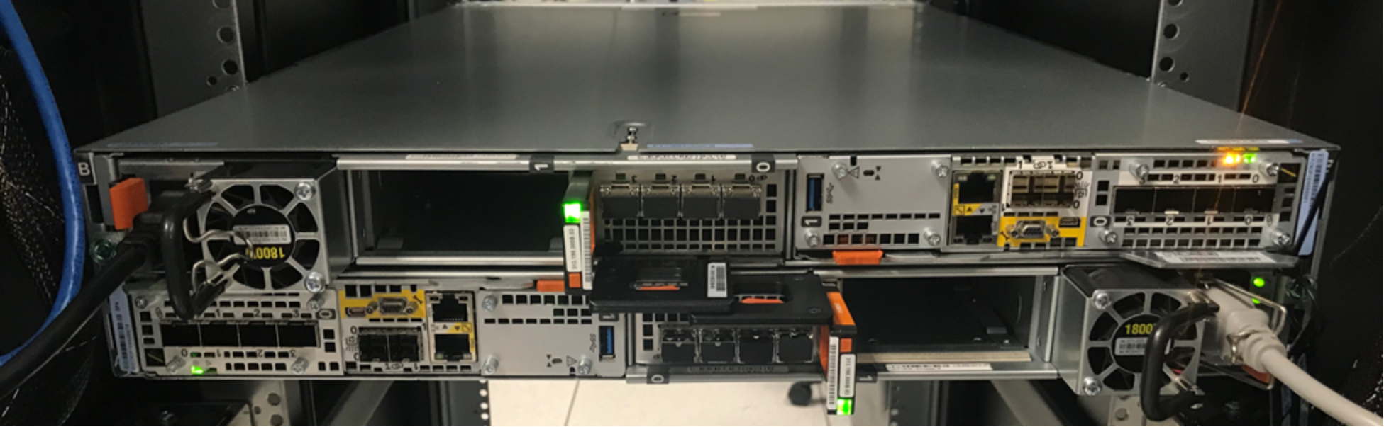
Figure 11. Rear of DPE (480/F, 680/F, 880/F)
Storage Processor – 480/F, 680/F, 880/F
The purpose-built Unity XT platform for 480/F, 680/F, and 880/F systems are powered by an Intel® Xeon® Processor utilizing Intel’s Skylake architecture, depending on the system model and the core count will vary between 8 to 18 cores per CPU with two CPUs per Storage Processor. Each purpose-built system contains two Storage Processors (SP), which are used for high availability and load balancing purposes.
M.2 SSD – 480/F, 680/F, 880/F
There are two M.2 SSD devices, one connected using SATA protocol and one connected using NVMe protocol, located inside each Storage Processor for 480/F, 680/F, and 880/F systems. The devices serve two separate purposes; one as a backup device in the event of an SP failure (Figure 12) and one as a boot device for the system operating environment (Figure 13). In the event of an SP failure, the memory contents of the SP’s cache are written to the M.2 NVMe SSD device so the data can be recovered once the SP is restored. If the M.2 NVMe SSD device itself encounters a failure, cache data can be recovered from the peer Storage Processor. The M.2 SATA SSD device holds the boot image that is used to boot the operating environment.
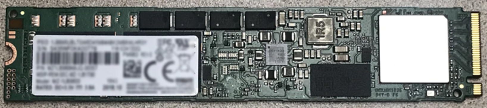
Figure 12. M.2 NVMe SSD Device (480/F, 680/F, 880/F)
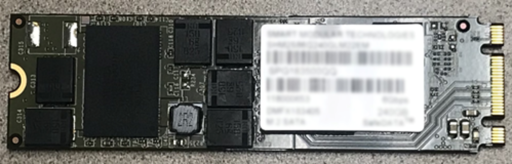
Figure 13. M.2 SATA SSD Device (480/F, 680/F, 880/F)
Cooling Modules – 480/F, 680/F, 880/F
Cooling modules or fan packs are used to provide cool airflow to the Storage Processor’s interior. There are six counter-rotating cooling modules in a Storage Processor for 480/F, 680/F, and 880/F systems. A Storage Processor can tolerate a single cooling module fault; the surviving fans will increase their speed to compensate for the faulted module. If a second cooling module faults, the Storage Processor will gracefully save write cache content and shut down.
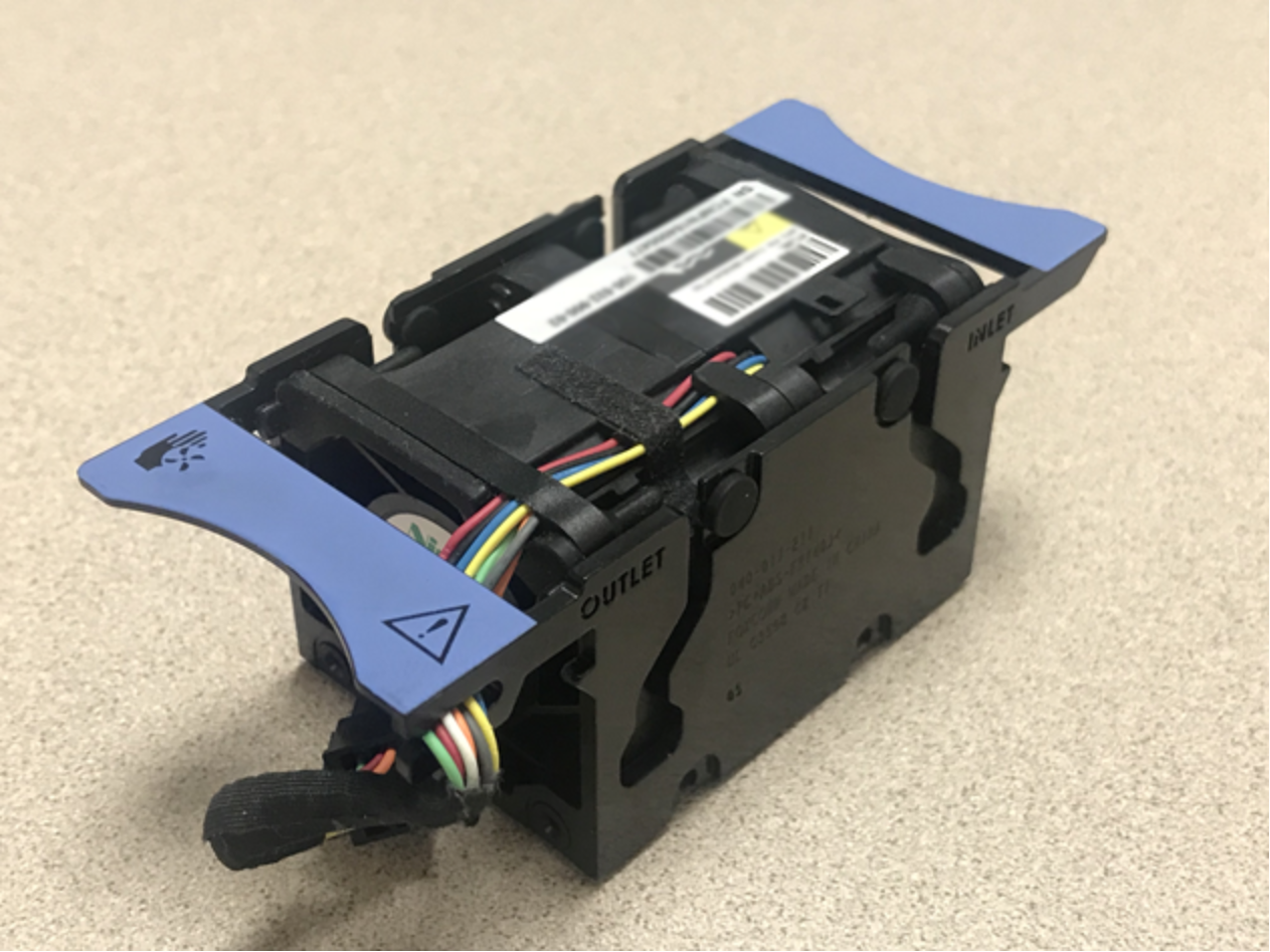
Figure 14. Cooling Module (480/F, 680/F, 880/F)
Battery Backup Unit (BBU) – 480/F, 680/F, 880/F
The Battery Backup Unit (BBU) provides power to the Storage Processor if cabinet power is lost. The BBU is designed to power the SP long enough for the system to store SP cache content to the M.2 SSD devices before powering down. The BBU includes sensors which communicate its charge and health status to the SP. In the event the BBU is discharged, the SP will disable cache until the BBU has recharged. In the event the BBU has faulted or cannot sustain enough charge, an alert will be generated.
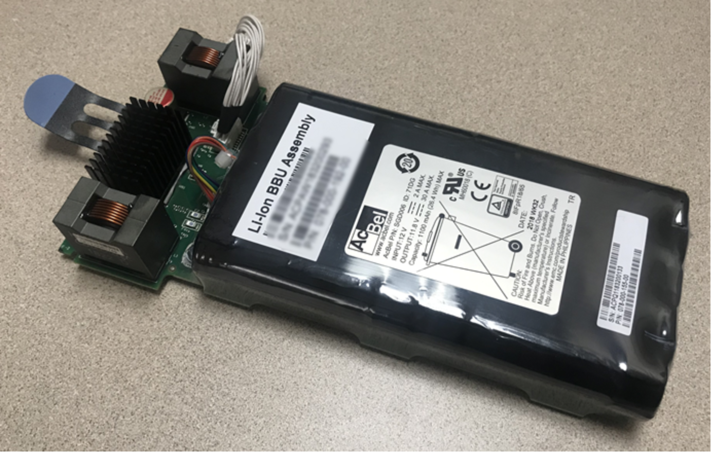
Figure 15. Battery Backup Unit (480/F, 680/F, 880/F)
Baffle – 480/F, 680/F, 880/F
The baffle directs airflow within the Storage Processor. Cool air drawn in from the cooling modules is directed to the processor and DIMMs for effective thermal management.
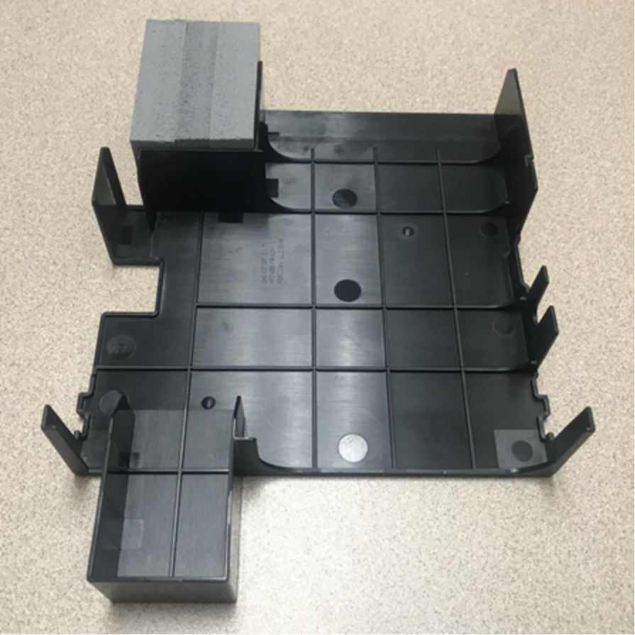
Figure 16. Baffle (480/F, 680/F, 880/F)
Dual-Inline Memory Module (DIMM) – 480/F, 680/F, 880/F
There are twenty-four Dual-Inline Memory Module (DIMM) slots on a Storage Processor. These are filled with up to 12 DIMMs depending on model. An example DIMM is represented in Figure 17. DIMMs are between 16 and 32GB in size and use error-correcting code (ECC) to protect against data corruption. If a DIMM is faulted, the system will boot into Service Mode so the faulted DIMM can be replaced.
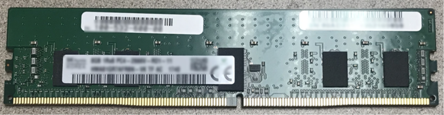
Figure 17. Dual-Inline Memory Module (DIMM) (480/F, 680/F, 880/F)
Power Supply – 480/F, 680/F, 880/F
There are two power supply modules in a Disk Processor Enclosure (DPE). A single power supply is capable of powering the entire DPE. Power supplies can be replaced without having to remove the Storage Processor. Power supplies are offered for AC power only.
Dell Unity OE version 5.2 introduced DC variant power supplies for Dell Unity XT 380/F and 480/F models which are NEBS compliant. DC power supplies are not available for the 680/F and 880/F. For Unity XT 380 and 480 DC powered systems, 600GB and 1.8TB 10k SAS NEBS drives as well as 800GB 3WPD SSD NEBS certified drives are available. For Unity XT 380F and 480F DC powered systems, 1.92TB and 3.84TB 1WPD SSD NEBS drives are available.
For more information about Dell Unity DC-powered systems, see the technical paper called Dell Unity DC-Powered Enclosures Installation & Operation Guide.
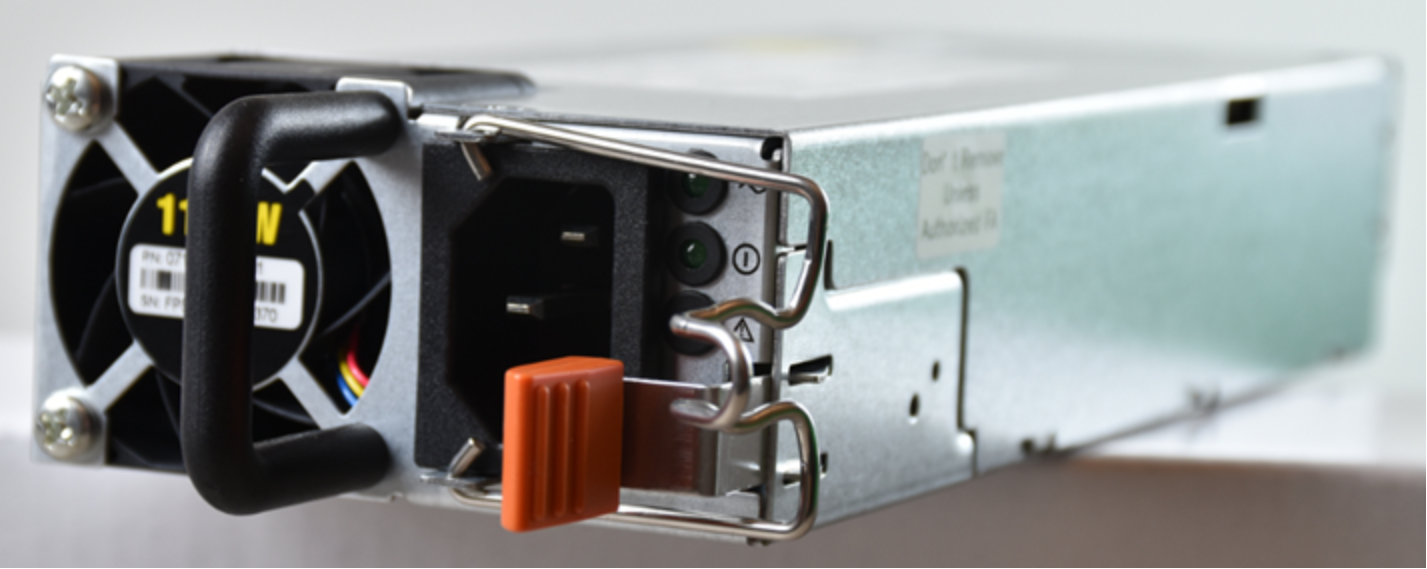
Figure 18. Power Supply (480/F, 680/F, 880/F)