
Introduction
Introduction
-
The Dell SRM solution has three logical layers:
- Presentation layer (Frontend servers)
- Database layer (Primary and Additional Backend servers)
- Collection layer (Collector servers)
The following figure shows the application components deployed within each of the three layers:
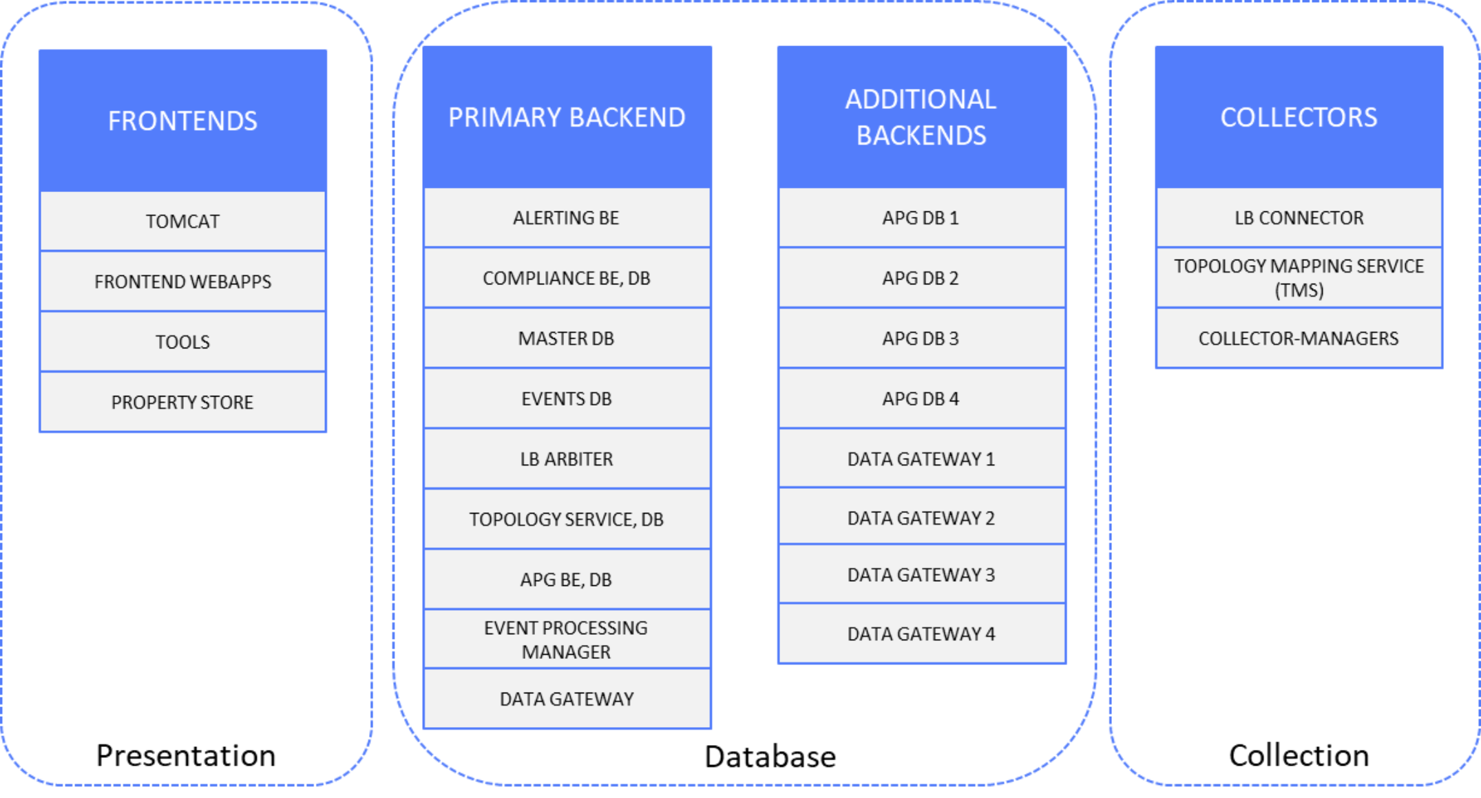
Figure 1. SRM logical layers
A description of each component and its communication with other components follows:
- Presentation layer
- Tomcat
Web server (mandatory on all Frontend servers where some Frontend webapps must run)
- Frontend webapps (FE)
Webapps deployed under Tomcat web server instance. Some well-known webapps are:
- APG-Frontend (reporting frontend)
- APG-Web-Service (webservice API for data retrieval from database or report)
- Alerting-Frontend (manage alert rules that are processing alerts received by alerting BE)
- Centralized-Management (SRM administrator UI)
- Compliance-Frontend (storage compliance frontend)
- Device-Discovery (device discovery UI)
- APG-REST-API
- Tools (TOOLS)
Frontend-report-generator tool for scheduled reports
- Property store (PS)
Storage engine that caches properties locally
Deployed on frontend server with various webapps that are using database queries
Accessed by collectors for data enrichment
- Database layer
- Alerting backend (ABE)
Receives raw values on a socket from collector managers (CM)
Receives events on a socket from event processing manager (EPM)
- Compliance backend (CBE), compliance database (CDB)
Provides data to compliance frontend
Feeds compliance database
- Master database (master)
Keeps local database authentication credentials for users, roles, and profiles information; database resources; and report templates loaded by frontend webapp
Updated from Admin UI of frontend webapp (users/roles/profiles), upon any changes in report tree (that is, report template modifications) or by adding or modifying database resources using frontend command manage-resources
Communicated by each frontend server to keep all users with respective reports synchronized across all frontends
- Events database (events_db)
Keeps the following “events” database tables used by Alert Consolidation instance of EPM component (see the EPM description later in this list):
- genericevents_live
- genericevents_archive
- Load Balancer Arbiter (LBA)
Single instance needed per site (PROD and DR)
Communicates with backend instances and provides balancing keys (such as device-to-backend mapping) and backend sockets details to underlying Load Balancer Connectors (LBC)
- Topology service (TS), topology database (RDF)
Aggregates topology graph data generated by each remote TMS (on Collector servers)
Provides a SPARQL endpoint for PTF queries from collectors, and provides capability to create REST resources
- APG backend (BE)
Time-series backend receives raw values on a socket from collector managers
Writes data to time-series APG database (mysql)
Accessed by frontend for metrics removal (Management of Database Metrics UI)
- APG database (DB)
Persistent storage for time-series data
Keeps data in the following tables:
- data_variable (keeps unique variable ID and unique variable name)
- data_property (keeps properties related to unique variable name)
- cache_group_* (keeps raw values and timestamp for variable IDs from data_variable table)
Accessed by most of frontend webapps
- Event Processing Manager (EPM) – focus is on Alert-Consolidation instance
Receives events and SNMP traps from underlying sources, processes them, and sends them to alerting backend
Writes processed events to events database
Sends events to compliance backend for impact analysis
- Collection layer
- Load Balancer Connector (LBC)
Single instance needed per Collector server
Communicates with LBA over webservice gateway and retrieves balancing keys (such as device-to-backend mapping), and backends socket details
Sends raw values to remote backend instances directly
Sends alerts to alerting backend
- Data Gateway (DGW)
Collector manager with optional filters, used to replicate raw data over two or more socket connectors
- Topology-Mapping-Service (TMS)
Receives raw values on a socket from collector managers and converts them to topology objects into RDF cache
Sends generated topology objects to Topology backend over its webservice gateway socket
- Collector-Managers (CM)
Collector managers containing various collectors that generate raw time-series values
Sends raw values to LBC and TMS
Queries Property Store on frontend servers for data enrichment
Queries Topology Service on primary backend server for data enrichment