
SRDF/Metro
SRDF/Metro
-
This solution focuses on SRDF/Metro, which significantly changes the behavior of SRDF/S mode regarding remote device availability to better support host application in high availability environments. With SRDF/Metro, the secondary SRDF device (the R2) is also read/write-accessible to the host and takes on the federated personality of the primary device (the R1): geometry, device WWN, and so on.
Because they provide a federated personality on the R2 device, both R1 and R2 devices can appear as a single virtual device across the two SRDF paired arrays for host presentation. The host (or hosts, in a cluster) can read and write to both devices. SRDF/Metro ensures that each copy remains current and consistent and addresses any write conflicts that might occur between the paired SRDF devices.
The following figure shows two SRDF/Metro configurations. The top half shows an SRDF/Metro configuration with a stand-alone host. The host has visibility to both the R1 and R2 arrays by using multipathing software such as Dell PowerPath technology to enable parallel reads and writes to each array. The lower half of the graphic shows a clustered host environment, where each cluster node has dedicated access to an individual PowerMax array.
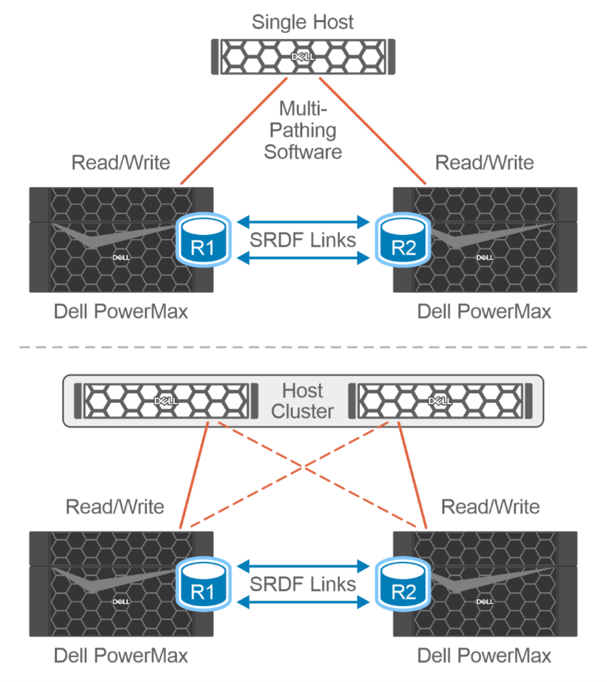
Figure 5. SRDF/Metro configurations: Stand-alone and clustered hosts
In both the stand-alone host environment and the clustered host environment, writes to the R1 or R2 devices are synchronously copied to their SRDF paired devices. If a conflict occurs between writes to paired SRDF/Metro devices, the conflicts are internally resolved to ensure that a consistent image between paired SRDF devices is maintained to the individual host or host cluster.
You can select and manage SRDF/Metro through Dell Solutions Enabler SYMCLI or Dell Unisphere for PowerMax (Unisphere) client software. You must install a separate SRDF/Metro license on each of the PowerMax systems to be managed.
SRDF/Metro uses the SRDF link between the two sides of the SRDF device pair to ensure consistency of the data on the two sides. If the status of the SRDF device pair becomes Not Ready (NR) on the SRDF link, SRDF/Metro must respond. SRDF/Metro chooses one side of the SRDF device pair to remain accessible to the host or hosts, while making the other side of the SRDF device pair inaccessible. The bias and witness options enable this choice. Both these options prevent data inconsistencies between the two sides of the SRDF device pair.
For more information, see the following documentation:
Bias
Bias is a function of the two PowerMax systems in the SRDF/Metro configuration and is a required and integral component of the configuration. The Create Pair operation places an SRDF device pair into an SRDF/Metro configuration and preconfigures the bias to the R1 side of the pair. You can change the bias when all SRDF device pairs in the SRDF group have reached the active/active SRDF pair state.
If the Remote Data Facility (RDF) device pair becomes NR on the RDF link, the nonbias side is inaccessible to the hosts while the bias side remains accessible to them.
Witness
Witness is an optional physical or virtual component of SRDF/Metro. The physical witness requires a third PowerMax array or a PowerMax array with the correct code. It is enabled through a special witness SRDF group that is created on each SRDF/Metro array and paired with the third witness array.
This solution uses a virtual Witness (vWitness), which is a virtual appliance (vApp) running on an ESXi host. The vApp maintains multiple IP connections to redundant management guests on both the primary and secondary SRDF/Metro-managed arrays. These IP connections use TLS/SSL to ensure connectivity between the vWitness and SRDF/Metro paired arrays, as shown in the following figure. When configured, a witness system supersedes the bias functionality unless a failure situation requires specific knowledge of the bias system. In such cases, the system defaults to the bias functionality.
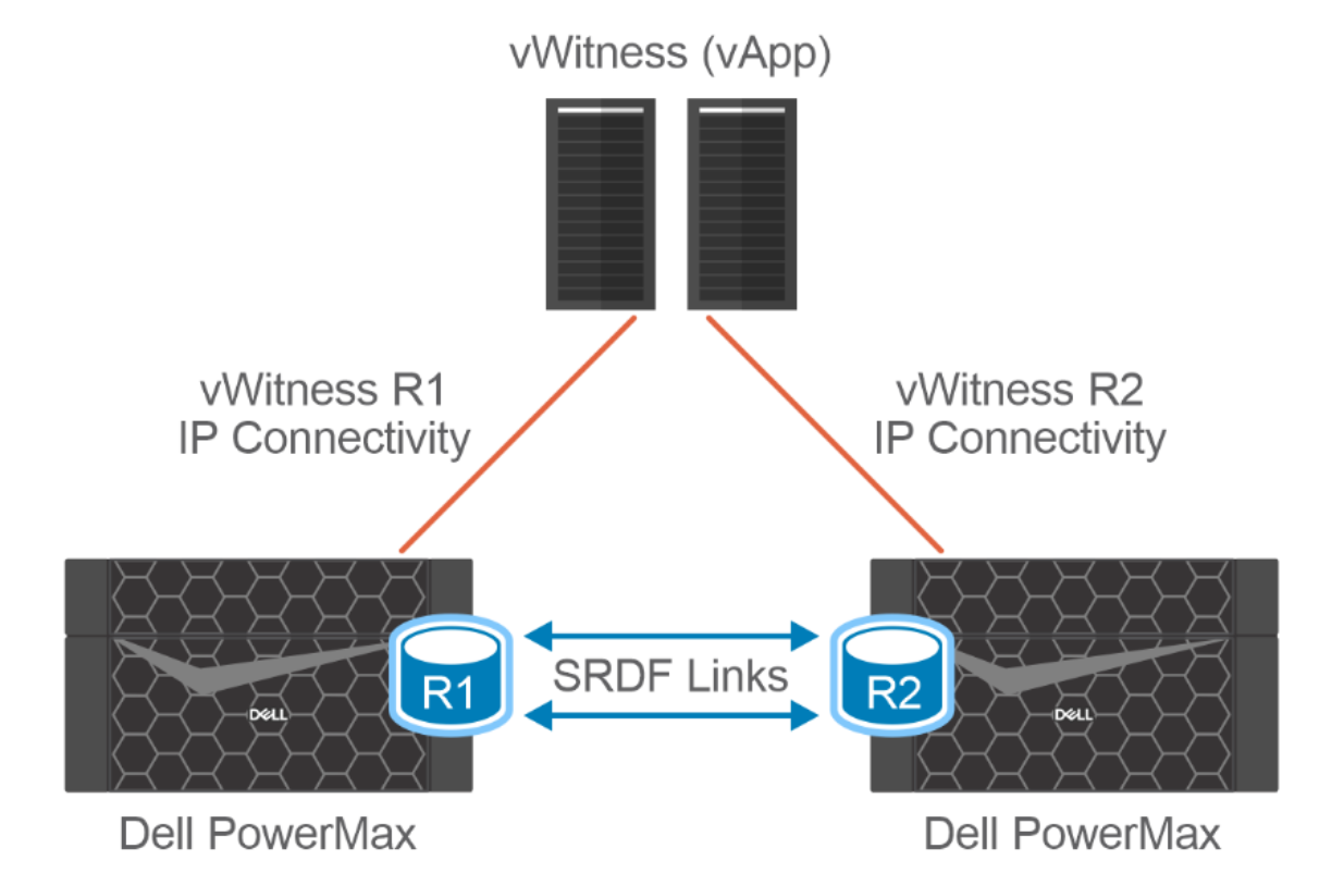
Figure 6. vWitness for SRDF Metro