
SAN-attached storage
SAN-attached storage
-
PowerVault ME5 arrays support SAN-attached Fibre Channel (16/32 Gb) and iSCSI (10/25Gb) connectivity. A switch-attached solution (or SAN) places a Fibre Channel or Ethernet switch between the servers and the controller enclosures within the storage system. Using switches, a SAN shares a storage system among multiple servers reducing the number of storage systems required for a particular environment. Using switches increases the number of servers that can be connected to the storage system to scale to greater than four servers, which is the limit for a direct-attached environment.
When designing a SAN, we recommend using two switches. This practice enables you to create a redundant transport fabric between the server and the PowerVault ME5 storage. This configuration also allows you to take an individual switch out of service for maintenance, or due to failure, without impacting storage-access availability.
When cabling the PowerVault ME5 controllers in a switched environment, pay close attention to the layout of the cables in both Fibre Channel and Ethernet fabrics. In the following figure, controller A (the left-most PowerVault ME5084 controller) has ports 0 and 2 connected to the top switch, and ports 1 and 3 are connected to the bottom switch. This configuration repeats in a similar fashion with controller B. The servers are configured with each server having connections to each switch. This cabling ensures that access to storage remains available between an individual server and the PowerVault ME5 array during switch maintenance.
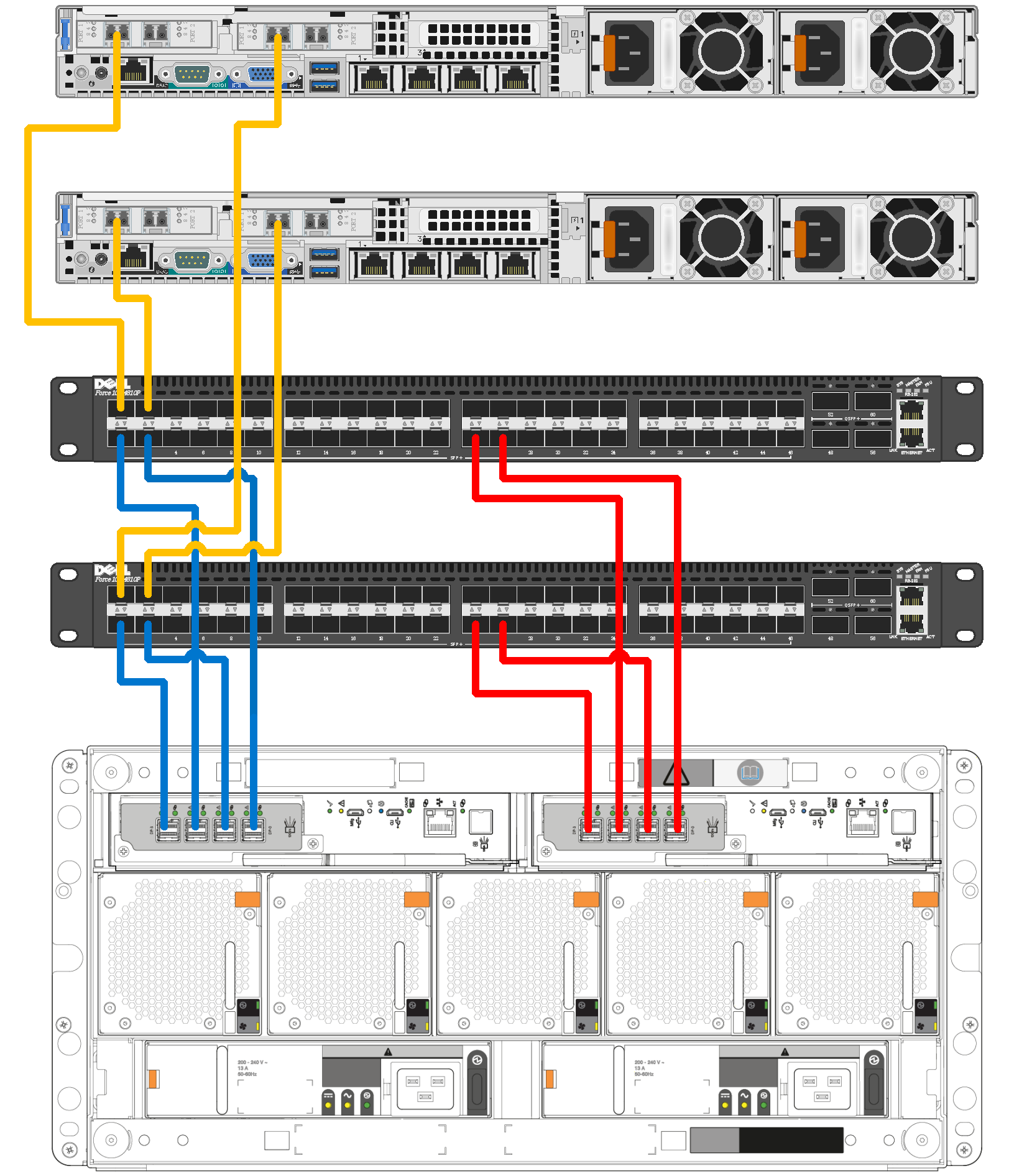
Figure 2. Connecting two hosts to a PowerVault ME5084 array using two switches
iSCSI fabric settings
This section details recommended and required settings when creating an iSCSI-based SAN.
Flow control settings
Ethernet flow control is a mechanism for temporarily pausing data transmission when data is being transmitted faster than its target port can accept the data. Flow control allows a switch port to stop network traffic sending a PAUSE frame. The PAUSE frame temporarily pauses transmission until the port is again able to service requests.
We recommend the following settings when enabling flow control:
- Enable a minimum of receive (RX) flow control for all switch interfaces used by servers or storage systems for iSCSI traffic.
- Enable symmetric flow control for all server interfaces used for iSCSI traffic. PowerVault ME5 automatically enables this feature.
Jumbo frames
Jumbo frames increase the efficiency of Ethernet networking and reduce CPU load by including a larger amount of data in each Ethernet packet. The default Ethernet packet size, or MTU (maximum transmission unit), is 1,500 bytes. With Jumbo frames, this size is increased to 9,000 bytes.
When enabling Jumbo frames, all devices in the path must be enabled for Jumbo frames for this frame size to be successfully negotiated. These devices include server NICs or iSCSI HBAs, switches, and the PowerVault ME5 storage. In a vSphere environment, the devices also include the virtual switches and VMkernel adapters configured for iSCSI traffic.
Jumbo frames and flow control
Some switches have limited buffer sizes and can support either Jumbo frames or flow control but cannot support both simultaneously. If you must choose between the two features, we recommend choosing flow control.
Fibre Channel zoning
Fibre Channel zones can segment the fabric to restrict access. A zone contains paths between initiators (server HBAs) and targets (storage array front-end ports). You can use either physical ports (port zoning) on the Fibre Channel switches or the WWNs (name zoning) of the end devices in zoning. We recommend using name zoning because it offers better flexibility. With name zoning, server HBAs and storage array ports are not tied to specific physical ports on the switch.
Zoning Fibre Channel switches for vSphere ESXi hosts is no different than zoning any other hosts to the array.
Zoning rules and recommendations:
- Connect the PowerVault ME5 array and ESXi hosts to two different Fibre Channel switches (fabrics) for high availability and redundancy.
- Use WWNs for name zoning.
- When defining the zones, it is a best practice to use single-initiator (host port), multiple-target (PowerVault ME5 ports) zones. For example, for each Fibre Channel HBA port on the server, create a server zone that includes the HBA port WWN and all the physical WWNs on the PowerVault ME5 array controllers on the same fabric. See the following table for an example.
Table 1. Fibre Channel zoning examples
Fabrics
(dual-switch configuration)
FC HBA port
(dual-port HBA configuration)
PowerVault ME5 FC ports
(FC port configuration)
Fabric one zone
Port 0
A0, B0, A2, B2
Fabric two zone
Port 1
A1, B1, A3, B3
Note: We recommend using name zoning and creating single-initiator, multiple-target zones.