
Remote systems configuration
Remote systems configuration
-
Creating and managing replication in PowerStore Manager is easy and intuitive. All replication operations, including configuring of replication network ports, replication connections, and replication sessions, can be performed in the PowerStore Manager UI. With the help of wizards, replication can be configured by IT generalists or by advanced users. Replication can also be configured using the PowerStore Manager CLI or REST API. For more information about configuring and managing replication using the PowerStore Manager CLI, see the Dell PowerStore Manager Command Line Interface Guide. For more information about the REST API, use SwaggerUI (https://<PowerStore_Cluster_IP>/swaggerui) or see the Dell PowerStore REST API Programmer’s Guide.
The following sections outline the remaining steps that are required to configure remote replication in PowerStore Manager. Each of the following operations is completed from a particular page in PowerStore Manager. Each page is discussed in detail in the following sections. For more information about using PowerStore Manager to configure and manage replication, see PowerStore Manager Online Help.
Storage network IPs and replication ports
When planning replication between two PowerStore arrays, consider the following:
- With PowerStore OS before 4.0, only one interface or system bond can be tagged for replication. If the system bond interfaces are connected to different switches, replication can continue even if one switch is down.
- PowerStoreOS 4.0 and later uses network groups for the remote system pair to specify the replication data networks. A remote system pair configuration can leverage multiple replication network groups to distribute the replication traffic.
- When file service is configured, configure a link aggregation interface for file services when using system bond for replication traffic.
- When host traffic is configured on an interface configured for replication, the available bandwidth is shared. This configuration can have an impact on host and replication performance.
- If host traffic and replication traffic are using the same network but different ports, configure host multipathing without using ports tagged for replication.
- In a configuration with multiple IP networks, the IP address ranges must not overlap with existing IP address ranges configured on the system.
- Only storage networks that are configured with an iSCSI purpose (OS <4.0) or replication purpose (OS 4.0 and later) can be used for replication.
- Depending on workload and data change rate on replicated volumes, a higher port speed might be required to steadily meet the RPO target for asynchronous replication. It is even more important when metro volumes or synchronous replication is set up for continuous replication.
- Starting with PowerStoreOS 3.0, it is also possible to use ports other than system bond for file I/O and to create additional link aggregation for file I/O.
Configure the replication network on each PowerStore cluster before setting them up as a remote system pair. The remote system pair configuration does not replicate the replication network configuration.
Replication data network configuration (PowerStoreOS 1.x-3.x)
This section shows the configuration for shared network ports as it has been supported since PowerStoreOS 1.x. A single storage network is used for host I/O or import, and replication-related data using the storage network. PowerStoreOS 2.x and later allows different storage networks for host access and replication data network.
Each port for a storage network configuration on a PowerStore requires its own IP address. When it is planned to extend an existing storage network, check the available storage IP addresses before creating interfaces. To verify the settings for storage network IPs, select Settings > Networking > Network IPs. Ensure that at least two storage network IPs for each appliance in the cluster configuration are unallocated for mapping new storage network ports which are distributed across the nodes. To tag new replication ports in PowerStore Manager, select Hardware > Appliance-Name, and select the Ports tab. All Ethernet ports and system-bond are eligible to be tagged as replication ports and are available in the ports list.
Figure 4
Figure 4shows the PowerStore Manager Ports page. The figure also shows the default Link Aggregation ports (system-bond/bond0) that are set up on the system and are already tagged for replication using Default Storage Network, which was created beforehand. From this page, you can map ports to the storage network and change the tagging of replication data interfaces.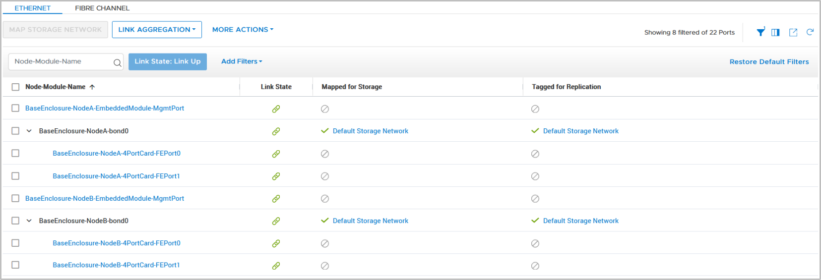
Figure 4. Ports overview page
To change the replication data port to a port other than the system bond or vFE1 Port on port group TGT1, map a new set of ports to the storage network. It is only required to run these steps for a single node. PowerStore Manager configures the peer node in parallel.
The example in Figure 5
Figure 5shows how to map a storage network:- Select the port.
- Click MAP STORAGE NETWORK.
If only a single port is selected, PowerStore Manager automatically configures the corresponding port on the peer node.
- Select the storage network to be mapped.
- Confirm the selected mapping with MAP STORAGE.
- To finish the configuration, confirm the following dialog.
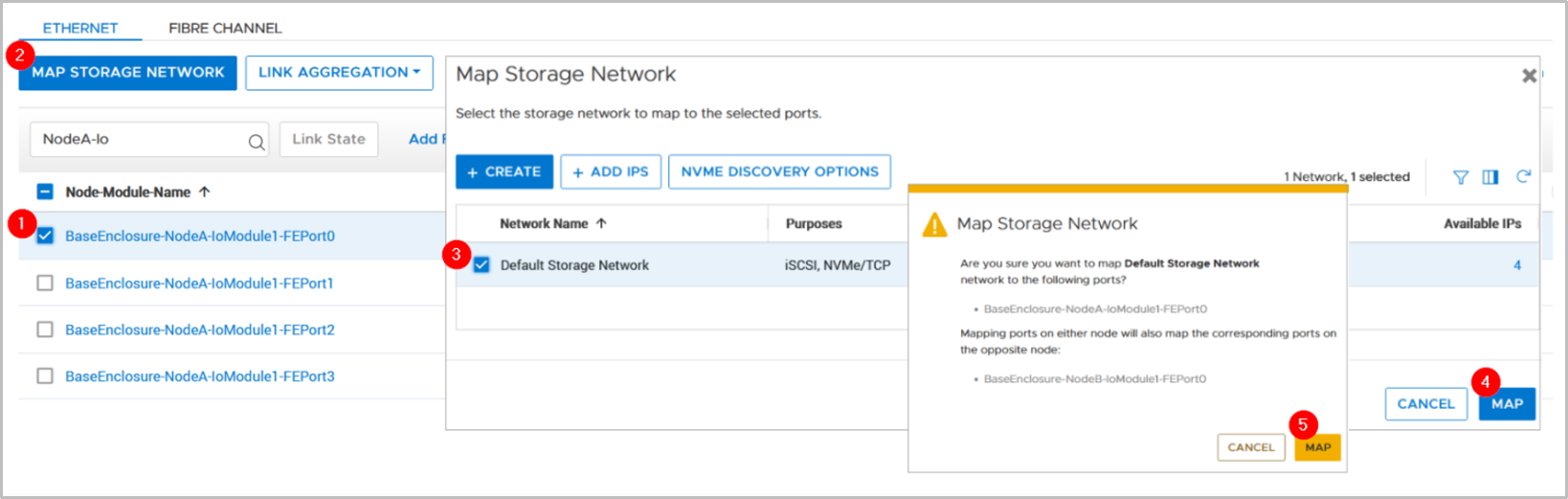
Figure 5. Map Storage Network
After ports are mapped to the storage network, select MORE ACTIONS > Tag for Replication, as shown in Figure 6
Figure 6. In the resulting window, click TAG PORT to finish the configuration. When it is set, the replication tag cannot be removed completely, but it is possible to reconfigure the replication tag for a different port or to a different storage network. Similar to mapping, it is always a pair of ports that are tagged for replication—one port on Node A and a corresponding port on Node B.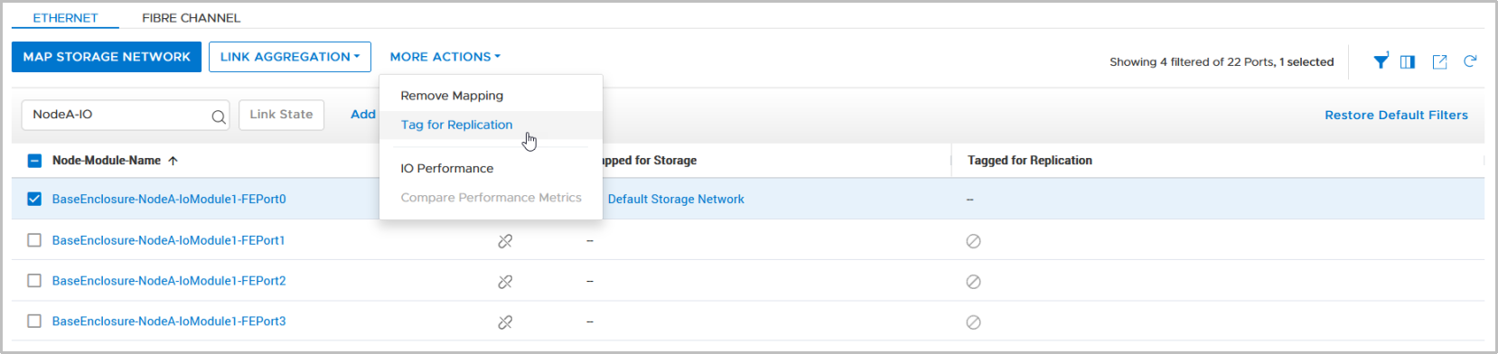
Figure 6. Tag port for replication
Individual networks for host and replication traffic
Starting with PowerStoreOS 2.0, multiple storage networks are supported. This feature allows users to separate host data from replication data either using same or different ports.
The following examples are using Default Storage Network and Replication Network (Figure 7) as already configured networks in PowerStore Manager (configured by selecting Settings > Networking > Network IPs > Storage).
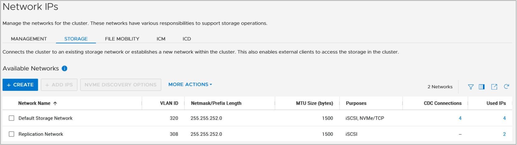
Figure 7. Multiple storage networks
Example 1: Two storage networks over a single port
When physical links for a storage network are not fully used by host data, it might be useful to set up a shared port for host data and replication data. To separate the traffic, it is required to set up VLANs on the switch ports. This example is using VLAN 320 for host access and VLAN 308 for replication traffic. The configured VLANs in PowerStore Manager must match the switch port configuration (VLAN tagging). As in previous sections, the port configuration in PowerStore Manager is available in the Hardware > Appliance-Name > Ports view. Figure 8
Figure 8shows the current configuration where system bond is tagged for host I/O and replication using the mapped storage network Default Storage Network.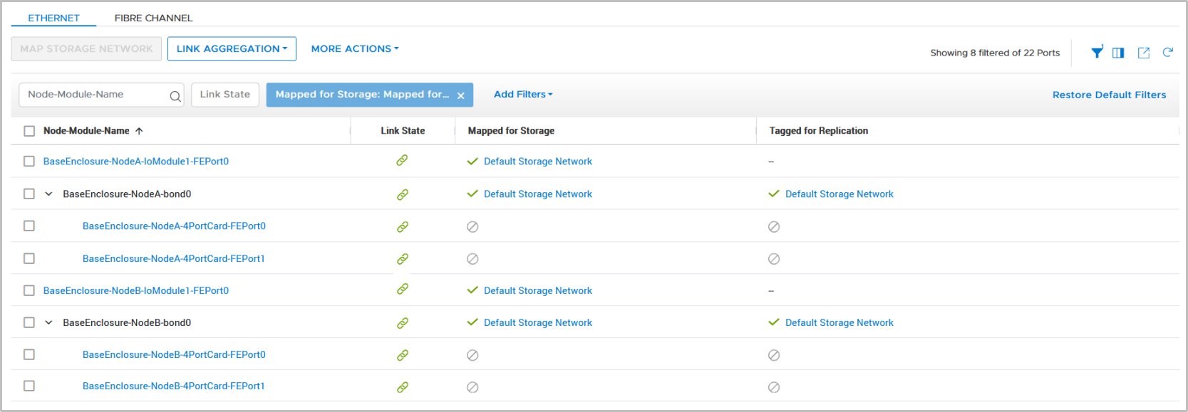
Figure 8. Single network configuration
For replication tagging, configuring the additional storage network is required. Replication Network as the second Storage Network for the port pair was created in network settings in advance. Because the port configuration is the same on partner nodes, it is only required to select one single port for configuration and use the MAP STORAGE NETWORK button. In the selection window that is displayed, choose the Replication Network and continue with MAP NETWORK (Figure 9).
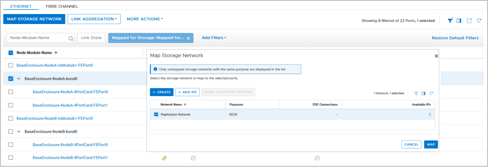
Figure 9. Map Storage Network
When the Map Storage Network dialog is confirmed, the port overview column Mapped for Storage changes to 2, which indicates that two storage networks are mapped and using this port. Hovering over the number shows the IP address information for the ports (Figure 10).
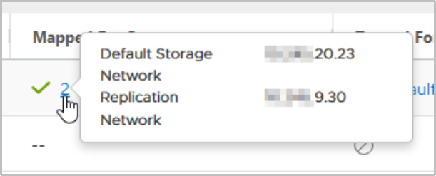
Figure 10. Detailed port information
The mapped network can be tagged as a replication network as in a single network configuration. Now you can choose the network used to tag the selected port, as shown in Figure 11.
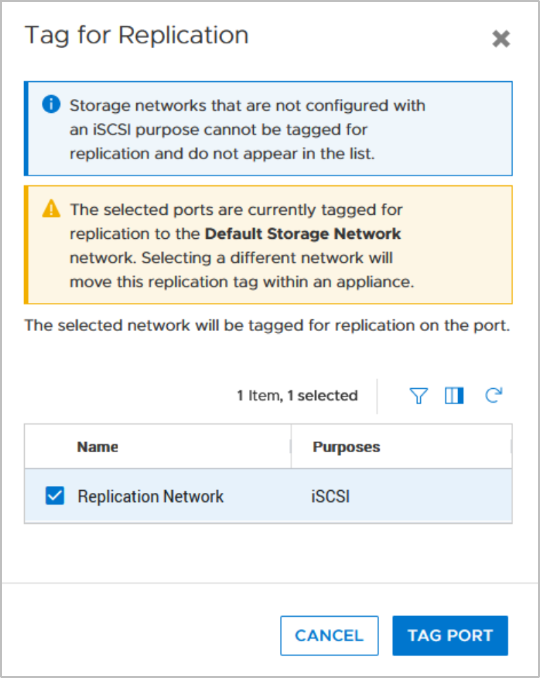
Figure 11. Tag for Replication – Network selection
After the dialog to perform configuration on both nodes is confirmed, the tagged network for replication changes to the new Replication Network (Figure 12
Figure 12).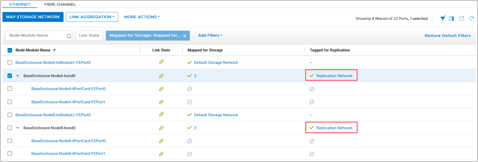
Figure 12. Single port configuration with dedicated network tagged for replication
Example 2: Separated host and replication networks
Note: This example uses the system bond as a replication port, which might not be the optimal configuration for all use cases.
In some use cases, it might be useful to separate the replication data network from production host traffic by using different physical ports and networks. The configuration is similar to Example 1. The difference is to map the Replication Network to another port than the Default Storage Network, which is used for host traffic. The example in Figure 13
Figure 13shows a selected port with a dialog box to select the storage network for mapping.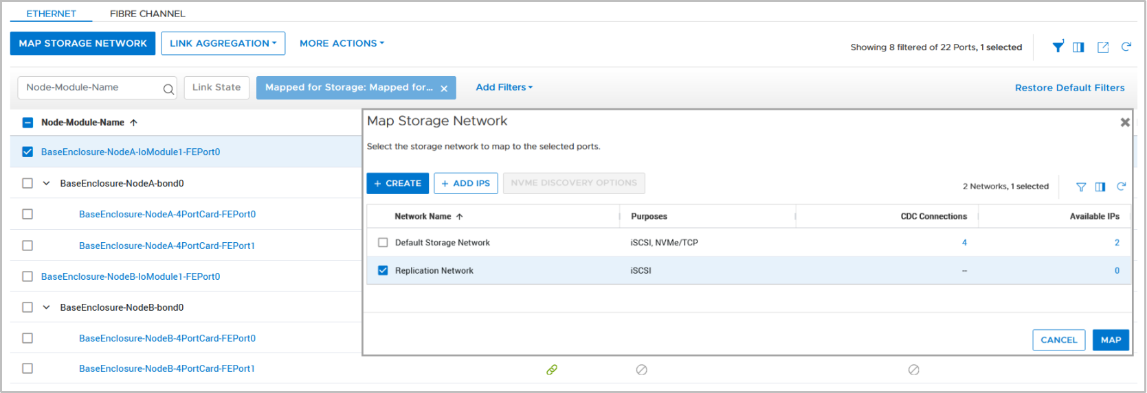
Figure 13. Map replication network to a new network port
After the configuration is finished, it is possible to tag the new storage network port for replication. Because only one storage network is configured in our example, there is no additional dialog to select the network. The port is tagged with Replication Network after the configuration is confirmed. Figure 14
Figure 14shows the configuration for that example.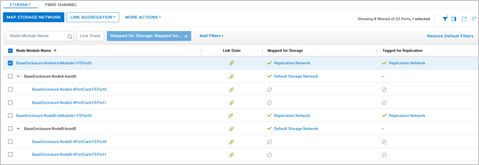
Figure 14. Port configuration with dedicated host and replication storage network
Replication data network configuration (PowerStoreOS 4.0 and later)
This section addresses the new replication data network confirmation in PowerStoreOS 4.0 and later. A replication data network relies on a TCP connection over one or multiple networks for the replication, consisting of a network port and an IP configuration. An IP storage network leveraged for replication requires setting its purpose to Replication. The purpose can be set when a new storage network is created or when modifying an existing storage network in Settings > Networking > Network IPs > Storage Networks (Figure 15
Figure 15).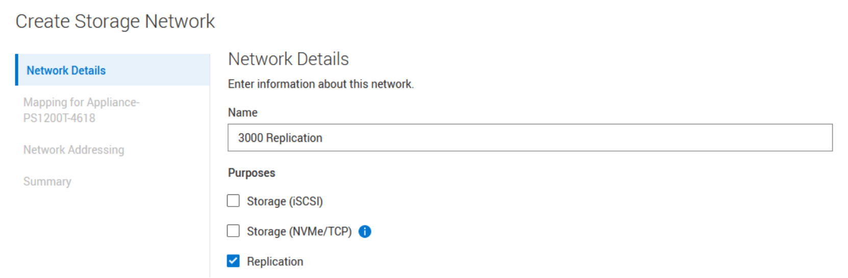
Figure 15. Create Storage Network with replication purpose
Creating the Storage Network in the next step allows the user to map the network to a port. A previous set purpose is adopted to the port during the mapping process and is available in the column Port Assigned Purposes (Figure 16
Figure 16).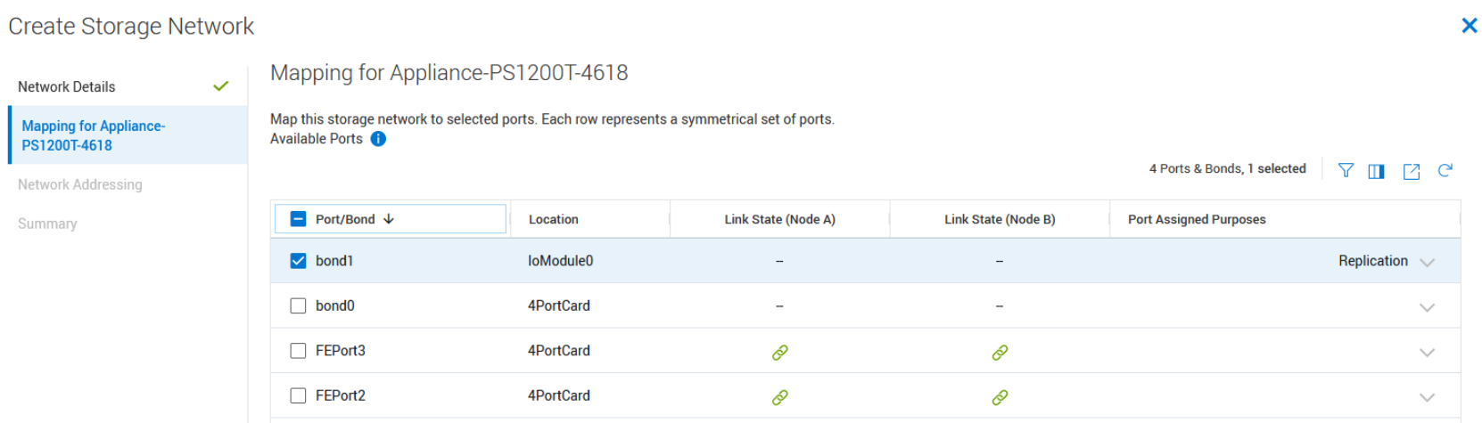
Figure 16. Replication network to port mapping
After the configuration wizard finishes, the storage network overview shows the network name, VLAN ID, and the configured purpose for the individual storage networks in the column Purposes (Figure 17
Figure 17).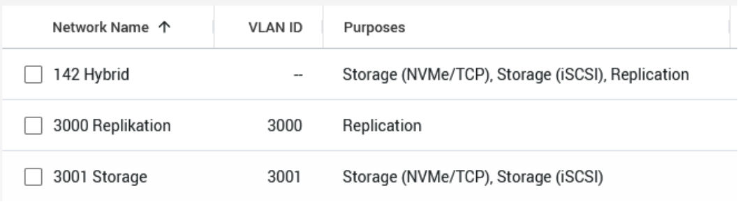
Figure 17. Storage Networks with different purposes
The current usages of a port are determined by the storage network(s) to which it is mapped. This information can be found in the PowerStore Manager ports view Hardware > [Appliance Name] > Ports (Figure 18
Figure 18).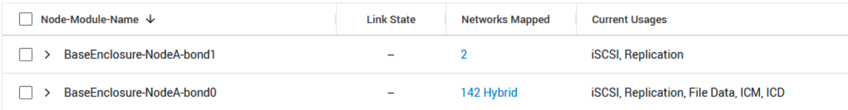
Figure 18. Ports view with usages
The Current Usages column in the Ports view shows the usages of the individual ports. For instance, port BaseEnclosure-Node-A-bond0 has 142 Hybrid network mapped. The port is used for iSCSI, Replication, File Data, ICM, and ICD. The number “2” in the Networks Mapped column indicates two mapped networks for port BaseEnclosure-Node-A-bond1 and the link behind the number leads to a slide out that shows all configured IP networks for that port (Figure 19
Figure 19).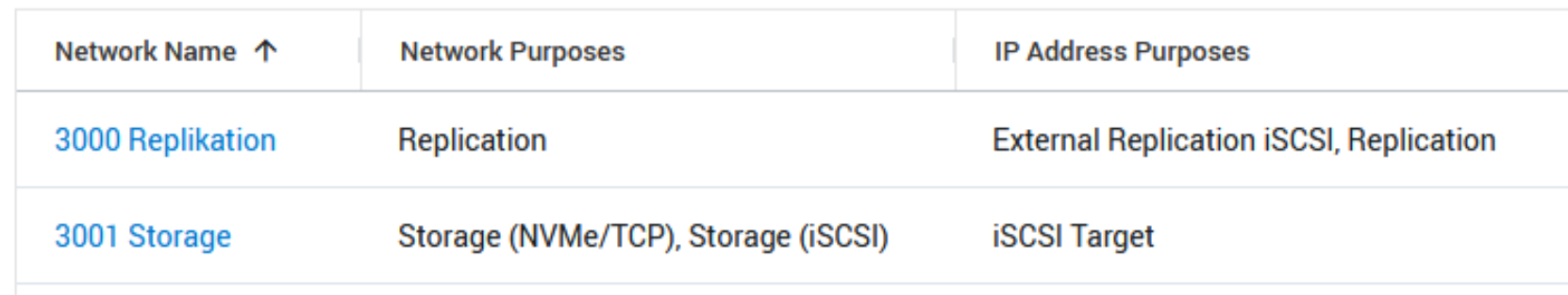
Figure 19. Storage networks mapped to a port
All network port configurations for a PowerStore appliance are symmetric for both nodes. When changing the configuration on one node port of the appliance, it immediately affects the same port on the other node. Only ports with Replication usage can be used for a replication network group in a remote system pair configuration.
Remote systems
The next step in configuring remote replication is to create a remote systems pair with another system. Configuring a remote system pair is only required once for both systems. After configuration, the remote system pair is available on both participating PowerStore clusters. For replication management, a private replication connection using the management ports is set up. To set up a replication connection, select Protection > Remote Systems to start adding remote systems (see Figure 20).
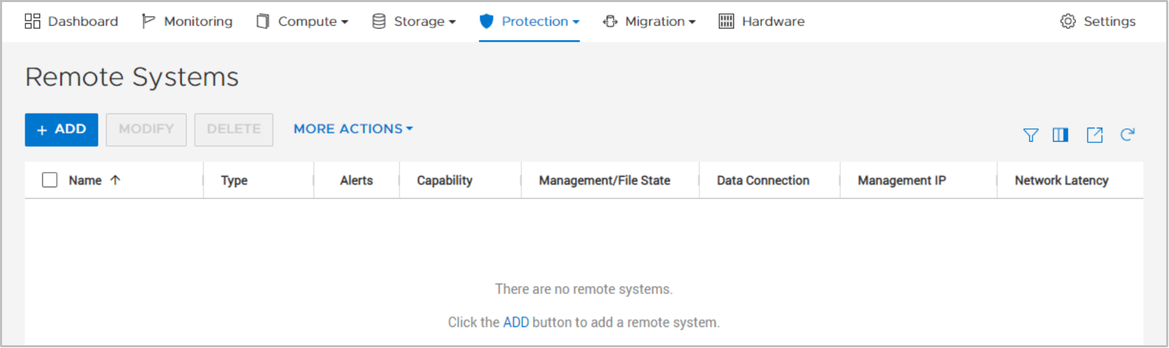
Figure 20. Remote systems replication setup
To define a new remote system, click ADD as shown in Figure 20. The Add Remote System window that is displayed (Figure 21) requires the following information:
- Management Cluster IP Address
- Username and Password of the remote system
- Network Latency setting
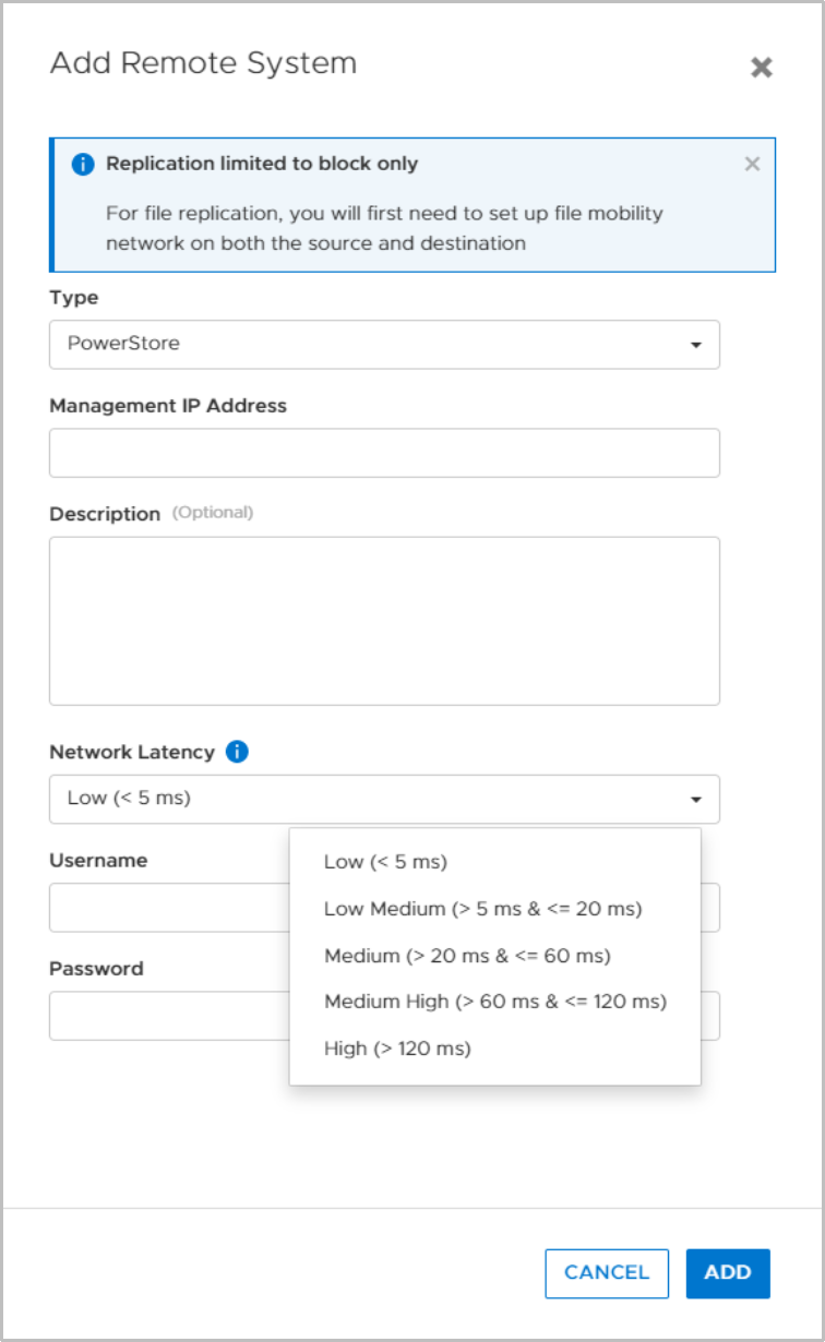
Figure 21. Add Remote System
Replication traffic can be tuned for higher efficiency depending on the expected network latency. When network latency between the remote systems is unknown, use the ping utility to determine the latency. For PowerStoreOS releases 1.x and 2.x, use Low when the expected latency is less than 5 milliseconds, otherwise use High. PowerStoreOS 3.0 and later allows a more granular setting of network latency, as shown in Figure 21
Figure 21. Metro and synchronous replication require a low latency network (<5ms).The provided credentials for a configured user are not stored on the system and are only used for the relationship setup. After the relationship is set up, PowerStore uses SSL certificate-based authentication. When the required fields are entered, click ADD. Because the management connection for the remote systems pair uses SSL encryption, it is required to confirm the remote SSL certificate. After the configuration task is finished, the new remote system is listed on both sides. If using bi-directional replication, the same remote systems pair can be used for replication sessions from the opposite systems.
After a remote system is set up, select MORE ACTIONS > Verify and Update. This action verifies that the selected replication connection still exists with the remote system, and it updates the connection details if any changes were made. Figure 22
Figure 22shows the Remote Systems Overview. The Capability column indicates the supported types of replications for the remote system pair. The Management/File State and Data Connection columns indicate the link status.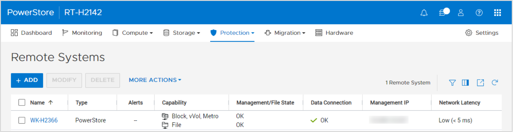
Figure 22. Remote Systems Overview
Replication data network
For PowerStoreOS releases 1.x and 2.x, the iSCSI protocol is used for replication data traffic. PowerStoreOS 3.0 and later leverages a proprietary TCP-based protocol for replication data traffic which is mandatory for a metro configuration. The TCP-based replication protocol improves replication performance between systems with network impairment, such as high latency or packet loss. Replication between earlier releases and PowerStoreOS 3.x is supported and relies on the iSCSI protocol. Starting with PowerStoreOS 4.0 TCP-based replication is the only supported protocol for replication. An NDU to 4.0 or later is blocked when a remote system pair is still configured with an iSCSI based replication protocol. PowerStore Manager will show an alert that the iSCSI based protocol is used, and provides a link for the update to the TCP based replication protocol. Each latency category uses a different network port number. For replication across network borders, adjusting network ACL or network firewall rules might be required to allow replication traffic. Table 3
Table 3shows an overview of different network latency settings and the network port that is used on PowerStore.Table 3. Remote systems network latency overview
PowerStoreOS versions
Network latency between remote systems
Port #
PowerStoreOS
1.x, 2.x
Low (default)
< 5 milliseconds
3260
High
>= 5 milliseconds
3261
PowerStoreOS
3.0 and laterLow (default)
< 5 milliseconds
13333
Low Medium
>= 5 and < 20 milliseconds
13334
Medium
>= 20 and < 60 milliseconds
13335
Medium High
>= 60 and < 120 milliseconds
13336
High
>= 120 milliseconds
13337
PowerStoreOS 4.0 and later is no longer limited to the single storage network which is tagged as the replication network. One or more replication networks can be configured in a network replication group, on a remote system pair granularity. The replication network pair is automatically established by the remote system pairing when both PowerStore systems use the same IP network port for replication. When more network ports do have replication usage, a manual configuration is required. After an NDU from an earlier release, a post upgrade service starts the migration of the replication purpose tagged storage network towards the new concept of network group for the replication. After selecting a remote system pair (Figure 23
Figure 23), the replication network configuration is in the Protection > Remote Systems overview, in the More Actions pull down.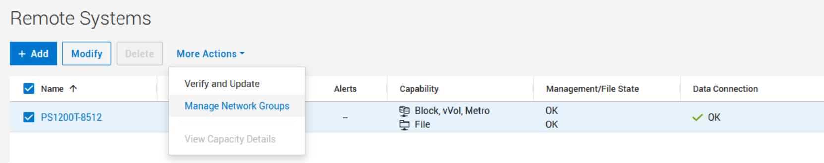
Figure 23. Remote Systems – Manage Network Groups
For a remote system pair there must be at least one network group configured. The slide out to manage network groups allows you to modify existing network groups, as well as to create and delete a network group (Figure 24
Figure 24).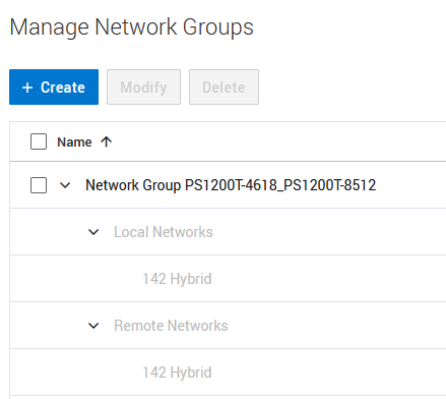
Figure 24. Manage Network Groups
When you create a new replication network group, the wizard shows the available local and remote networks you can select for replication (Figure 25
Figure 25). Remote networks are fetched during the remote system pairing and are synchronized when verifying and updating a remote system pair configuration (More Actions – Verify and Update).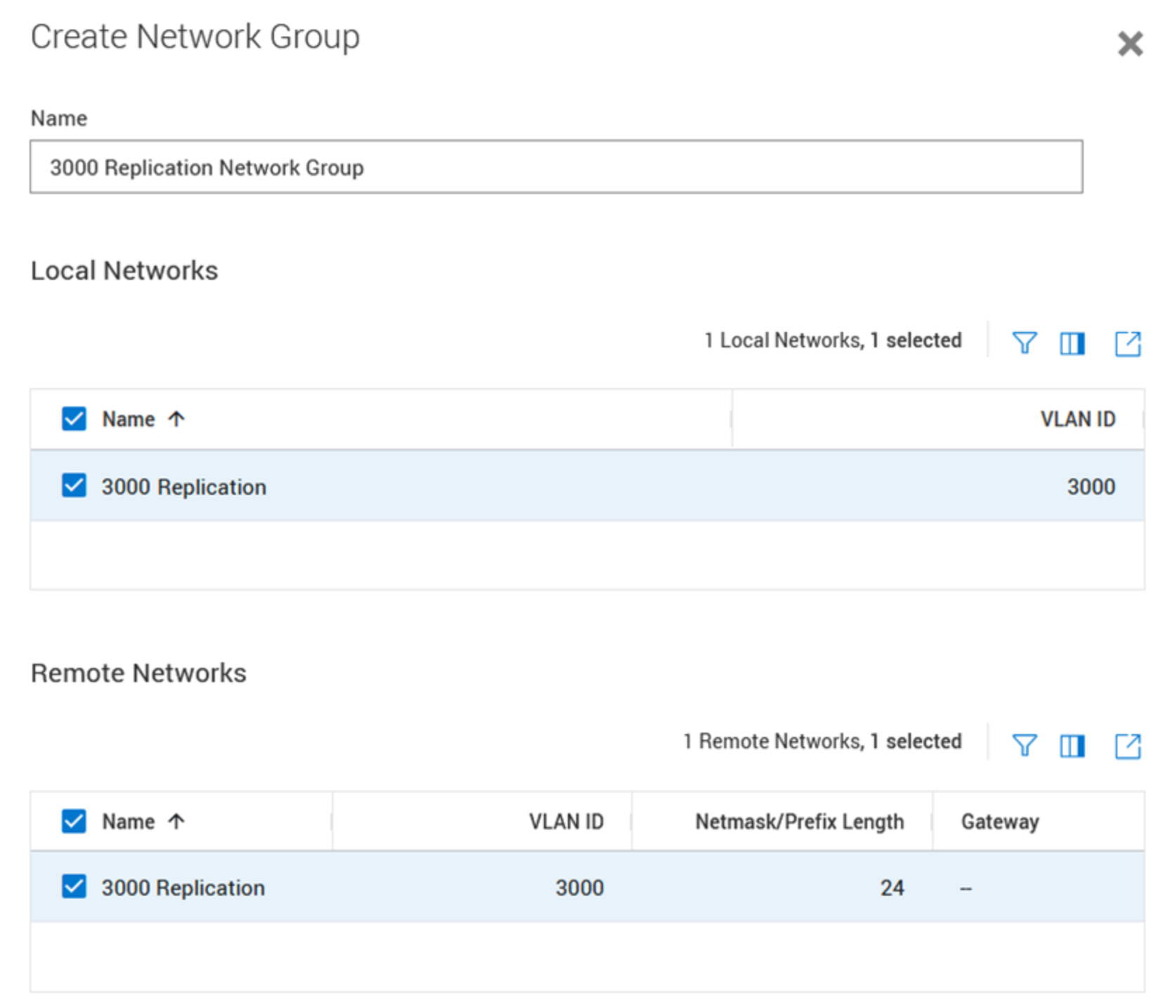
Figure 25. Create replication network group wizard
PowerStore has no limitation on which IP ports and networks are used for the replication network groups, as long as Layer 2 (switched) or Layer 3 (routed) communication is possible between systems in a remote system pair configuration. The networks shown in the dialog only rely on the configured purpose and resulting replication port usage. That flexibility allows for multiple different replication networks for the remote system pair and enables additional advanced configuration to control the network used for replication traffic. Bear in mind that replication networks’ performance for a metro or synchronous replication configuration have a direct influence on host IO performance.
Use case examples:
- A remote system pair can leverage multiple groups of different IP networks on a potentially different physical network infrastructure for a dual fabric architecture used for replication.
- Even though you may plan to use the same IP networks to host front end access and replication, it is possible to set up distinct physical ports for the individual workloads.
- Different remote system pairs can use individual non-overlapping ports and networks for replication.
File mobility network
File replication requires an additional file mobility network configuration for control file related traffic between the clusters. The file mobility network resides in the same subnet as the PowerStore cluster management network and requires three additional IP addresses in that range for each PowerStore cluster. While PowerStoreOS 3.0 does not support any changes when file replication is configured, PowerStoreOS 3.2 supports deleting and changing the file mobility network in a paused state without needing to delete the existing replication sessions. Even though deleting the file mobility network is supported, it is required when replication sessions are activated again.
The configuration for the file mobility network (Figure 26
Figure 26) can be found on the File Mobility tab at Settings > Networking > Network IP. When the initial network configuration is finished, map the file mobility network to the PowerStore management ports of the appliance. For the Reconfigure or Delete tasks (PowerStore 3.2 and later), a dialog is displayed to confirm that no active file migrations or replication sessions are in place.Figure 26.
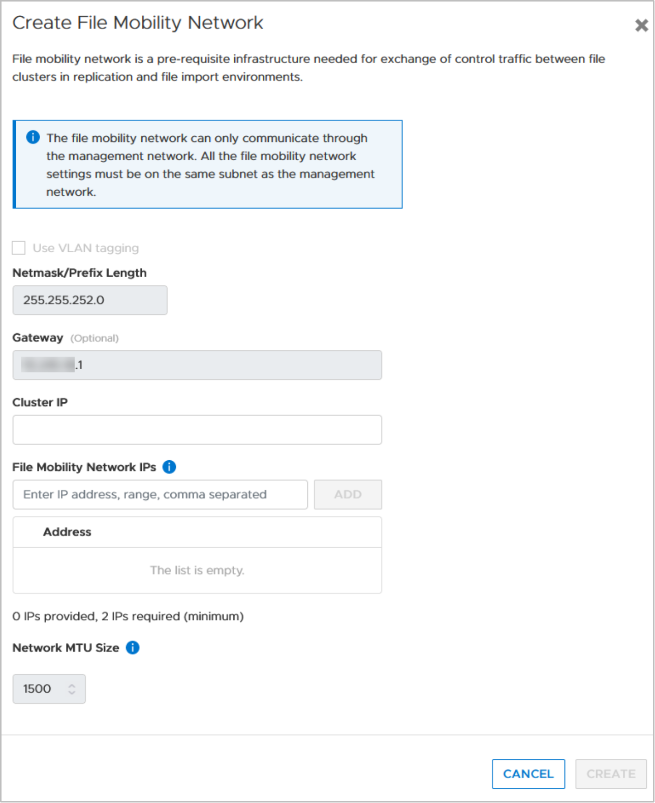
Create file mobility network