
Configuring LACP—NAS server
Configuring LACP—NAS server
-
Prior to PowerStore PSOS 3.0, single interfaces in PowerStore could be used as the network interface for NAS Servers. However, starting with PowerStore PSOS 3.0, PowerStore requires bonded interfaces for NAS Servers. This requirement was added to PowerStore to ensure high availability in NAS server connectivity.
Since PSOS 3.0+ requires bonded interfaces for NFS servers, the switch interfaces cabled to PS NAS bonded interfaces must be defined in a switch port channel.
PowerStore link aggregation configuration
With the initial release of PowerStore and PowerStoreOS 2, the first two ports of the 4-port mezzanine card were the only interfaces that supported link aggregation. PowerStore automatically created this link aggregation. This link aggregation was known as the system bond and was not user-configurable.
With PowerStoreOS 3, user-defined link aggregations are supported. LACP can be defined across two, three, or four ports, on the same card or I/O modules. Ports in that configuration must have the same speed, duplex, and MTU. User-created LACP is only supported for PowerStore NAS interfaces and is only available for PowerStore T models. For more information about what is user configurable, see the PowerStore documentation.
Note: Dell Technologies recommends using two TOR switches for redundancy. The lab used for this paper used only a single TOR switch.
Create either PowerStore Link aggregate or FNS network file interfaces before creating a PowerStore NAS server. If Link aggregates or FNS network file interfaces are not created first, the file interface in PowerStore Manager will have a degraded status.
When a bonded interface is configured in PowerStore Manager, the candidate interfaces for the bonded interface must be cabled and configured in both node A and node B. They must also be cabled to the appropriate port channel on the switch.
The following figure shows three link aggregations (bond0, bond1, and bond3). Each of the link aggregations is mirrored on both node A and node B.
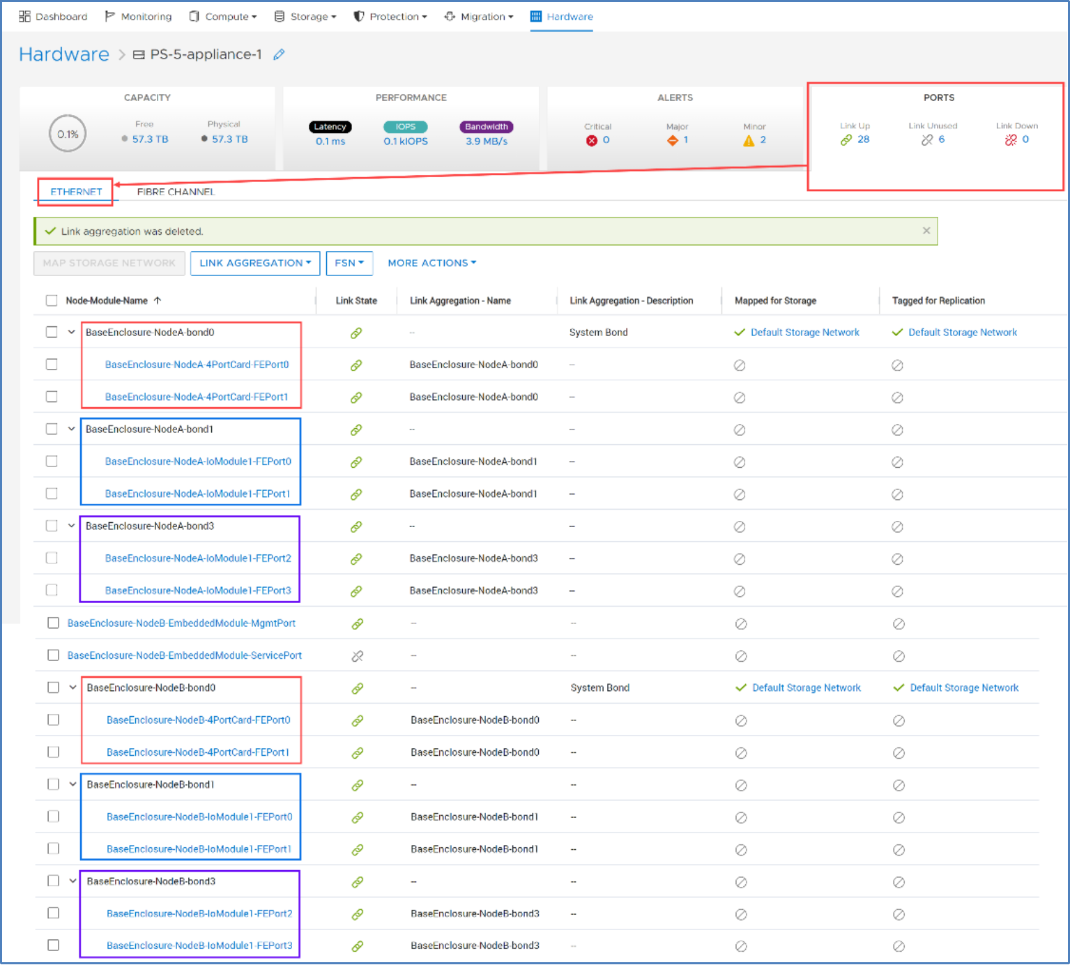
Figure 71. PowerStore bonded interfaces
This mirrored configuration is necessary because, in failover, the peer node uses the same ports. Link aggregations can be configured across ports from the same or different I/O modules within the same appliance, if the performance characteristics of the interfaces are the same.
The number of switch interfaces required for a PowerStore link aggregate is double the number of interfaces in the PowerStore link aggregate. If a PowerStore link aggregate contains two interfaces, four switch interfaces are required: two switch interfaces for the two interfaces in node A and two switch interfaces for the two interfaces in node B. Figure 72 shows the interface mappings between PowerStore bonded interfaces and the Ethernet switch port channels used in this paper.
Note: Dell Technologies recommends using two TOR switches for redundancy. The lab used for this paper used only a single TOR switch. Using one switch is not recommended.
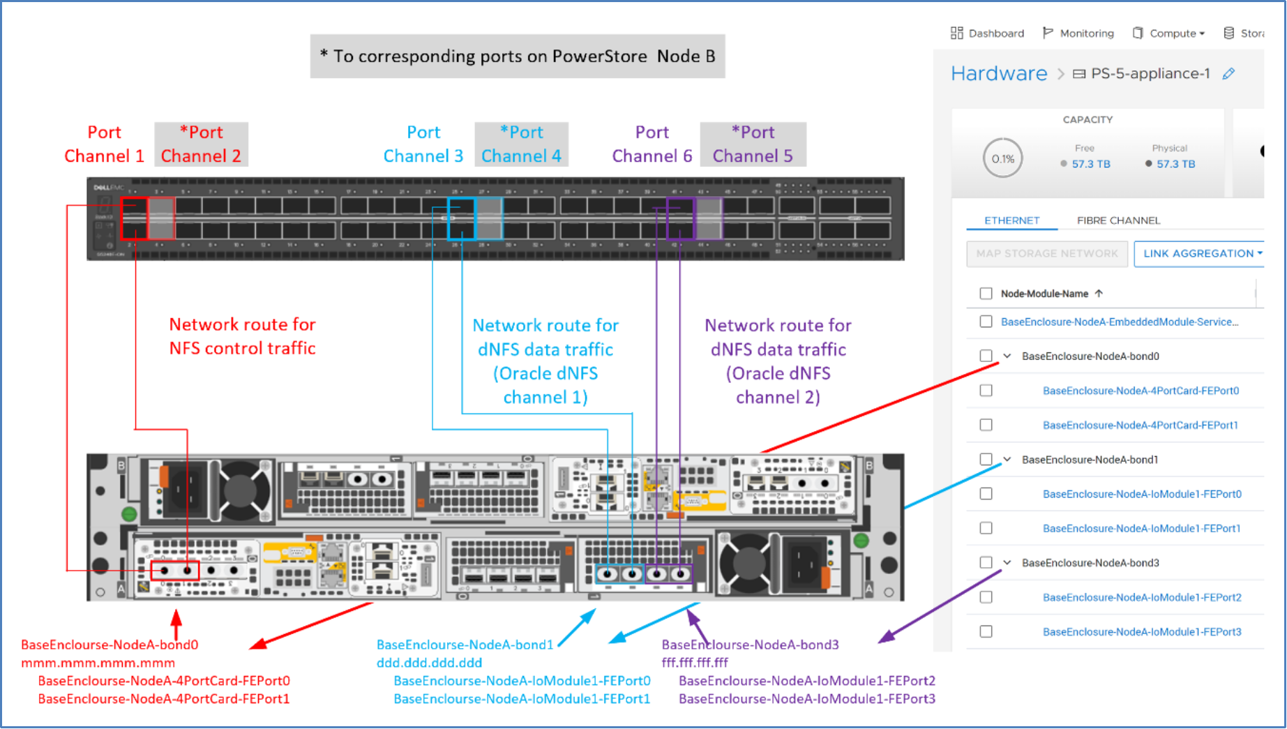
Figure 72. Interface mappings: PowerStore and Ethernet switch
To configure PowerStore link aggregations, perform the following steps in PowerStore Manager:
- Log in to PowerStore Manager.
- Click Hardware.
- Click the APPLIANCES tab.
- Click the appliance name where the link aggregation will be created.
- Click PORTS.
- Under the Node-Module-Name column, select the checkboxes corresponding to the interface members that will be members of the link aggregation:
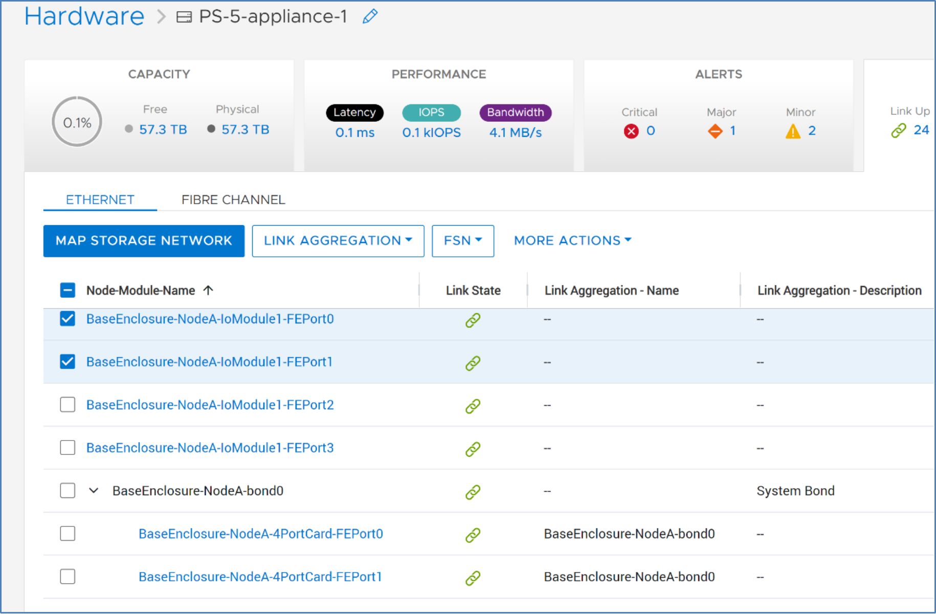
- Click LINK AGGREGATION.
- Click Aggregate Links.
- Provide an optional description.
- Click AGGREGATE.
Repeat this process for each required PowerStore link aggregate.
After a PowerStore link aggregate is created, it can be used as a NAS server network.
For information about creating a NAS server and assigning a bonded interface, see Creating a NAS server and adding a link aggregation network .