
Base enclosure
Base enclosure
-
The PowerStore base enclosure supports 25 all-NVMe 2.5-inch drives in a 2U chassis. The base enclosure is secured into a rack using toolless snap-in rails. The rails ship with every system and allow for easy installation of a PowerStore system. The base enclosure securely latches onto the snap-in rails when fully inserted into the rack. If you must remove the enclosure from the rails, lift a bottom latch on each side of the base enclosure to pull the base enclosure out. While the base enclosure securely latches onto the rails, there are optional screws underneath each latch that you can tighten for additional stability when moving the rack.
The front of the base enclosure contains an LED to display different states of the system. This LED is in the upper-left side of the chassis near drive slot 0. The LED states and corresponding system status are shown in Table 4. Each of the 2.5-inch drives contain both a drive power and activity LED, and a drive fault LED. The drive fault LED illuminates amber when a drive becomes faulted. There is also an option in PowerStore Manager to blink a specific drive to identify it using the fault LED. If the drive-power and activity LED is powered on and active, it blinks blue.
Table 4. Base enclosure LED status description
LED state
System status
Blue
Power is on. No fault has occurred.
Amber
Power is on. Fault has occurred within the enclosure.
Blue after amber alternating
Power is on. System is not initialized.
Off
Power is off.
The data storage drives are populated from left to right, starting in slot 0. PowerStore T models require a minimum of six storage drives while the PowerStore Q model requires a minimum of eleven storage drives. User data, metadata, and system data are automatically stored and protected across the available storage drives using the PowerStore Dynamic Resiliency Engine (DRE). For more information about PowerStore DRE, see the document PowerStore: Clustering and High Availability on the Dell Technologies PowerStore Info Hub.
PowerStore 1200 through 9200
The PowerStore 1200 through 9200 model appliances are available starting in PowerStoreOS 3.0 as PowerStore T systems. The base enclosure for PowerStore 1200, PowerStore 3200, PowerStore 5200, and PowerStore 9200 models supports 25 all-NVMe 2.5-inch drives in a 2U chassis. The following figure shows the base enclosure for a PowerStore system with 21 NVMe SSDs and four NVMe NVRAM drives.
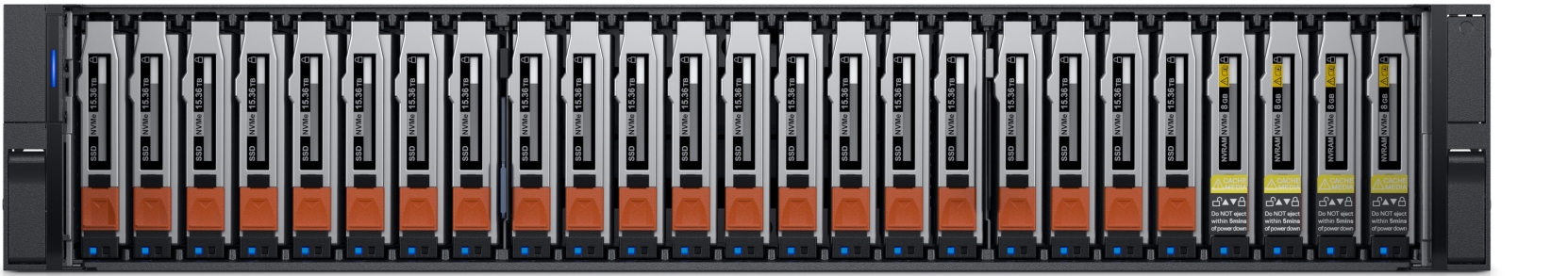
Figure 2. Base enclosure front view
The back of the base enclosure reveals the nodes and their connectivity options. Each node has one embedded module and two optional I/O module slots for host connectivity. Each node has a dedicated 1 GbE BASE-T service port that can be used for on-site support access and initial configuration of the system. Each node also contains a second 1 GbE BASE-T port that is used for management traffic. These 1 GbE BASE-T ports are both provided on the embedded module of the node.
For more information about the base enclosure and base enclosure components, see the PowerStore Hardware Information Guide on Dell.com/powerstoredocs.
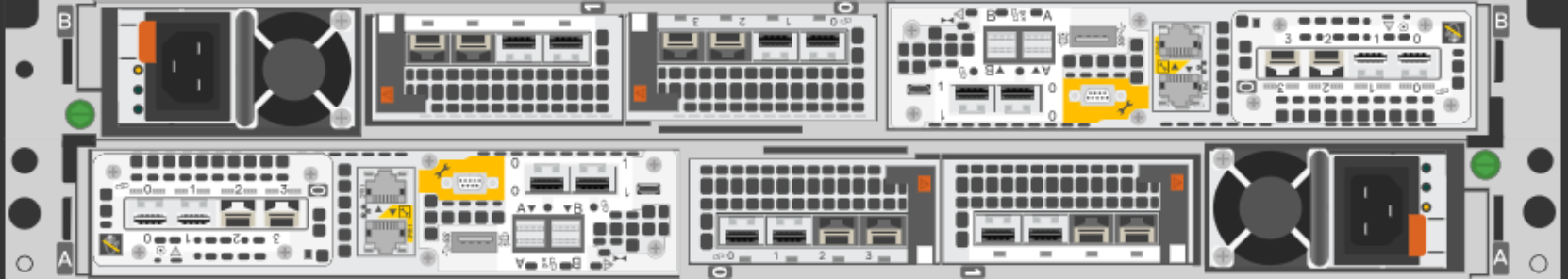
Figure 3. Base enclosure back view
Drives
The base enclosure is an all-NVMe platform, capable of supporting NVMe SSD, NVMe SCM, and NVMe NVRAM drives. You can populate slots 0 through 20 with NVMe SSD or NVMe SCM drives. Slots 21 through 24 are reserved for NVMe NVRAM drives that serve as write caching for user data. PowerStore 1200 and PowerStore 3200 models contain two NVMe NVRAM drives in slots 23 and 24. PowerStore 5200 and PowerStore 9200 models contain four NVMe NVRAM drives in slots 21 through 24. In models that only use two NVMe NVRAM drives, slots 21 and 22 are not available for storage drives.
PowerStore Q systems require a minimum of 11 NVMe QLC drives while PowerStore T systems require a minimum of six NVMe SSD or six NVMe SCM drives. Both Q and T systems can be scaled up in single-drive increments. PowerStore T Systems with at least six NVMe SSD drives can support one or more NVMe SCM drives for metadata tiering. NVMe SCM drives provide lower latency than NVMe SSD drives and can improve system performance by storing metadata on these low-latency drives. On a system that contains both NVMe SCM and NVMe SSD, the NVMe SCM drives are dedicated to metadata and all user data is stored on NVMe SSD drives.
PowerStore 1200 through 9200 model systems support up to three NVMe expansion enclosures per appliance for expanding capacity beyond the all-NVMe base enclosure with additional NVMe SSDs. NVMe expansion enclosures are not supported on systems that contain entirely NVMe SCM drives. NVMe expansion enclosures are supported on systems that have a mix of NVMe SSD and NVMe SCM in the base enclosure.
Node
The purpose-built PowerStore platform is powered by dual-socket upgraded Intel® Xeon® processors. Each purpose-built PowerStore system contains two nodes, which are used for high-availability and load-balancing purposes.
Each node is 1U in size and stacks vertically in the base enclosure, with the top node inverted. The bottom PowerStore node is node A, and the top PowerStore node is node B. Each node can access each drive through the midplane connection inside the base enclosure. Each node contains the following components:
- Internal M.2 boot module
- Fan modules
- Battery backup unit
- DIMMs
- Embedded module
- I/O module
- Power supply
Internal M.2 boot module
Each node has a primary and a secondary M.2 SATA device inside the system on a riser card between DIMM slots 11 and 12. The primary M.2 device is 240 GB and the primary boot device for the node. PowerStore uses this device to store the base operating system, log files, and for general system operations. The secondary M.2 device is 120 GB. PowerStore uses this device for recovery during a primary M.2 failure, and it is an alternate location for log files.

Figure 4. Internal M.2 boot module
Fan modules
PowerStore uses fan modules (cooling modules) to provide cool airflow to the node interior to ensure that the internal components remain at optimal operating temperatures. Each node contains seven redundant fan modules that are connected to the motherboard within the node. A node can tolerate a single fan module fault, and the surviving fans increase their speed to compensate for the faulted module. If two fan modules fault within the same node, the node performs a protective thermal shutdown. A protective thermal shutdown gracefully powers off the node, and any resource fails over to the surviving node.
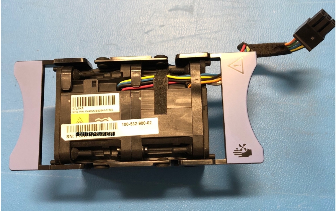
Figure 5. Fan module
Battery backup unit
If system power is lost, the battery backup unit (BBU) provides power to the NVRAM drive slots and the baseboard management controller (BMC). This action allows the NVRAM drives to vault their volatile data to nonvolatile storage within the same drive and persist the information. When the NVRAM drives have completed their vault, the BMC powers off the system.
The BBU in node A provides power for drive slots 21 and 23. The BBU in node B provides power for drive slots 22 and 24. The NVRAM drives are in mirrored sets consisting of drives in slots 23 and 24. If the PowerStore model supports four NVRAM drives, there is another mirrored set in slots 21 and 22. The node BBUs are configured so that both BBUs power each NVRAM mirrored pair, ensuring that there is no single point of failure. Each BBU contains sufficient charge to accommodate multiple back-to-back power failures. When power is resumed, the BBUs gradually recharge.
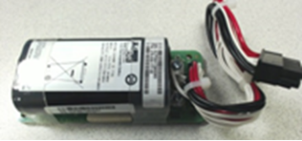
Figure 6. Battery backup unit
DIMMs
Each node contains 24 DDR4 DIMM slots used for DRAM, which are populated in different configurations that are based on the PowerStore model. All host data is written to the NVMe NVRAM drives from DRAM before the host is acknowledged, to protect against data loss upon system power failure.
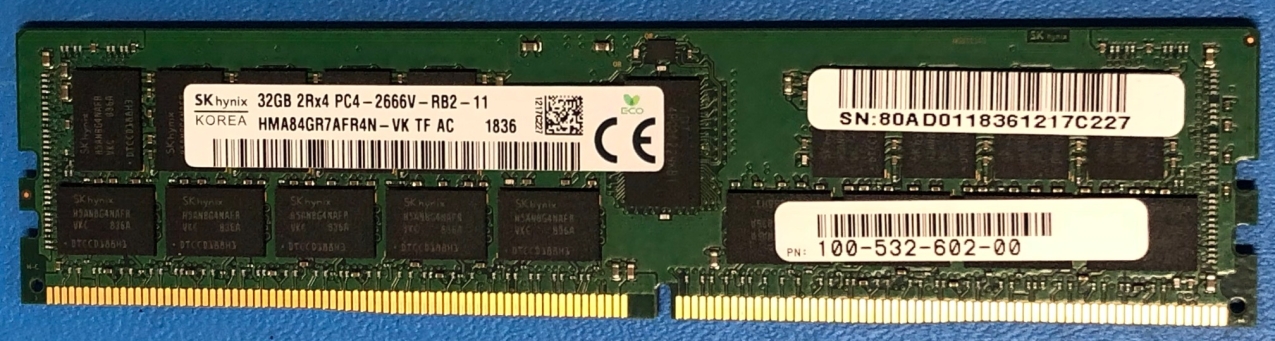
Figure 7. DIMM
Embedded module
Each node contains a single embedded module that includes various connectivity components. In PowerStoreOS 3.0, the PowerStore 1200, 3200, 5200, and 9200 models come with an upgraded embedded module where the SAS ports have been removed in order to support a 100GbE 2-port card for NVMe expansion enclosures. The 2-port card is optional at time of purchase and is required to support NVMe expansion enclosures. The embedded module also supports network connectivity for data storage, management and service access, and cluster communication. The embedded module contains the following components:
- 4-port card
- Non-maskable interrupt (NMI) button
- System management port (1 GbE)
- Service port (1 GbE)
- USB port (Disabled by default in PowerStoreOS 3.6 & later)
- 2-port card (for back-end connectivity only)
There are two 4-port card options that are supported in the embedded module:
- 10 GbE BASE-T
- 25/10 GbE optical/SFP+ and Twinax
The 4-port card for the embedded module on node A must be the same 4-port card in the embedded module on node B. You can select the 4-port card configuration at the time of ordering but cannot change the configuration later. In a multi-appliance cluster, you must configure ports 0 and 1 with a link speed of at least 10 GbE on the 4-port card. This configuration ensures that intra-cluster traffic, which uses ports 0 and 1, has sufficient bandwidth. The 4-port card supports iSCSI, file, NVMe/TCP, replication, and import traffic.
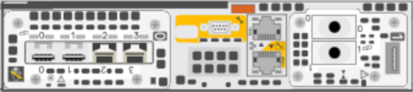
Figure 8. Embedded module with 25 GbE optical/SFP+ 4-port card
I/O module
Each node on PowerStore systems can support up to two I/O modules that provide extra connectivity for the supported front-end protocols, such as iSCSI, FC, file, NVMe/FC, NVMe/TCP, replication, and import. For the two nodes in a base enclosure, the I/O modules that are configured must match between nodes. During a node failure, matching I/O modules ensure that the peer node can begin servicing I/O using the mirrored I/O module.
PowerStore systems support the following I/O modules:
- 100 GbE optical/QSFP (2-port)
- 25/10 GbE optical/SFP+ and Twinax (4-port)
- 32/16/8/4 Gb Fibre Channel (4-port)
- 10 GbE BASE-T (4-port)
For more details about I/O modules, see I/O module.
Power supply
The PowerStore platform contains two power supply units (PSUs) in the base enclosure and offers PSUs with two wattage options that are based on the model. PowerStore 1200T, PowerStore 3200T, PowerStore 3200Q, and PowerStore 5200T models support both the 1800W high-line and 2100W high-line PSUs. PowerStore 9200T models support only the 2100W PSU. Do not select the 1800W PSU for environments with low-line power. For environments that only offer low-line power, you can use the 2100W PSU with a step-up transformer. The following table shows the PSU specifications for each PowerStore model.
Table 5. Power supplies
Model
Power supply wattage
Connector support
PowerStore 1200T, 3200T, 3200Q, 5200T
1800 W1 or 2100 W2
1800 W: C13/14 or C13/20
2100 W: C19/C20
PowerStore 9200T
2100 W2
2100 W: C19/20
1 Supports high-line power only
2 Supports high-line power and low-line power with step-up transformer
The following figure shows the supported connector types.
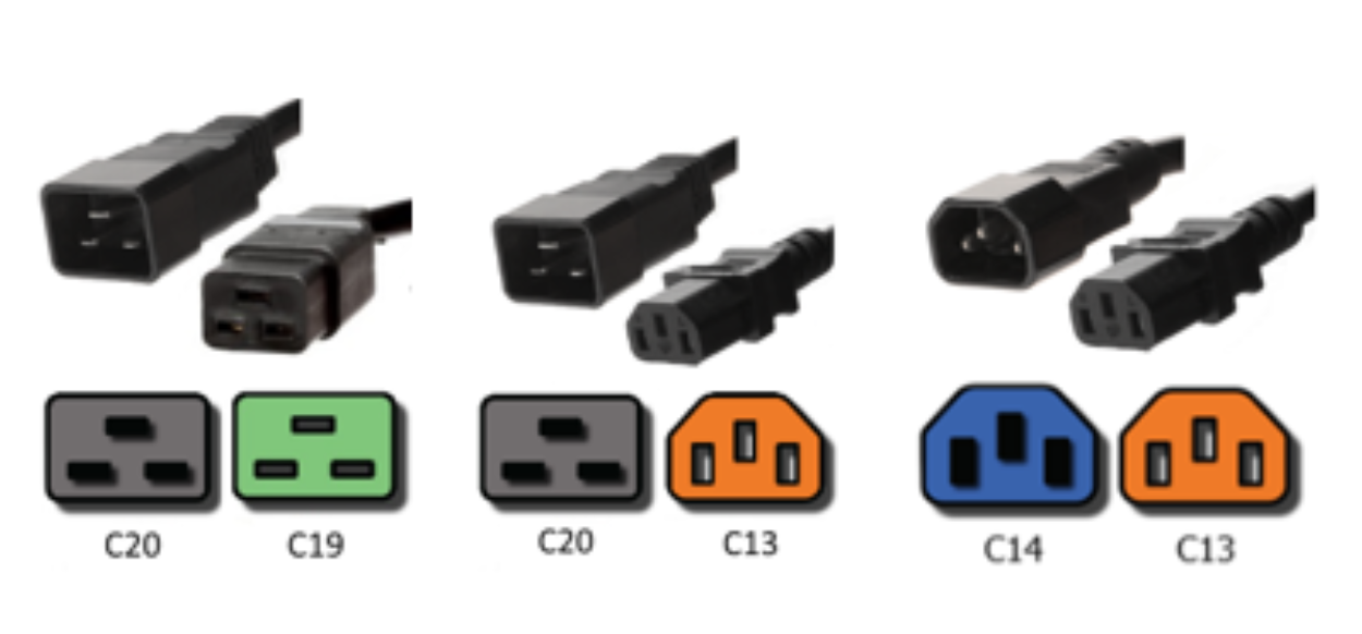
Figure 9. C19/C20, C13/C20, and C13/C14 connectors
A single power supply can power the entire base enclosure during a power supply failure. Power supplies can be replaced without having to remove the node. Power supplies are offered for AC power only.
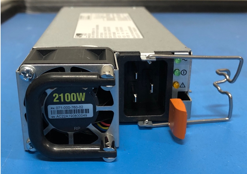
Figure 10. 2100 W power supply
PowerStore 1000 through 9000
The base enclosure for PowerStore 1000, PowerStore 3000, PowerStore 5000, PowerStore 7000, and PowerStore 9000 models supports twenty-five all-NVMe 2.5-inch drives in a 2U chassis. The following figure shows the base enclosure for a PowerStore system with 21 NVMe SSDs and four NVMe NVRAM drives.
Figure 11. Base enclosure front view
The back of the base enclosure reveals the nodes and their connectivity options. Each node has one embedded module and two I/O module slots (optional) for network connectivity. Each node has a dedicated 1 GbE BASE-T service port that can be used for on-site support access and initial configuration of the system. Each node also contains a second 1 GbE BASE-T port which is used for management traffic. These embedded 1 GbE BASE-T ports are both contained on the embedded module of the node.
For more information about the base enclosure and base enclosure components, see the PowerStore Hardware Information Guide on Dell.com/powerstoredocs.
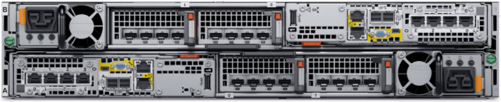
Figure 12. Base enclosure back view
Drives
The base enclosure is an all-NVMe platform, capable of supporting NVMe SSD, NVMe SCM, and NVMe NVRAM drives. You can populate slots 0 through 20 with NVMe SSD or NVMe SCM drives. Slots 21 through 24 are reserved for NVMe NVRAM drives, which serve as additional system write caching. PowerStore 1000 and PowerStore 3000 models contain two NVMe NVRAM drives in slots 23 and 24. PowerStore 5000, PowerStore 7000, and PowerStore 9000 models contain four NVMe NVRAM drives in slots 21 through 24. In models that only use two NVMe NVRAM drives, slots 21 and 22 are not available for storage drives.
Systems running PowerStoreOS 1.0 cannot mix NVMe SSD and NVMe SCM drives in the same base enclosure. PowerStore systems require a minimum of six NVMe SSD or six NVMe SCM drives, which can be scaled up in single-drive increments.
Starting with PowerStoreOS 2.0, systems can support one or more NVMe SCM drives mixed with NVMe SSD drives for metadata tiering. NVMe SCM drives provide lower latency than NVMe SSD drives and can improve system performance by storing metadata on these low-latency drives. On a system that contains both NVMe SCM and NVMe SSD, the NVMe SCM drives are dedicated to metadata and all user data is stored on NVMe SSD drives.
PowerStore 1000 through 9000 systems support SAS expansion enclosures for expansion capacity beyond the all-NVMe base enclosure using SAS drives. In PowerStoreOS 3.2, PowerStore 1000 through 9000 systems can convert to an upgraded embedded module to support NVMe expansion enclosures. For more details about upgrading the embedded module, see Embedded module conversion. SAS expansion enclosures are not supported on systems containing entirely NVMe SCM drives. Systems running PowerStoreOS 2.0 and containing a mix of NVMe SSD and NVMe SCM drives do support adding SAS expansion enclosures. For more details about PowerStore drives, see Drive model comparison.
Node
The purpose-built PowerStore platform is powered by dual-socket Intel® Xeon® processors. Each purpose-built PowerStore system contains two nodes, which are used for high-availability and load-balancing purposes.
Each node is 1U in size and stacks vertically in the base enclosure, with the top node inverted. The bottom PowerStore node is node A, and the top PowerStore node is node B. Each node can access each drive through the midplane connection inside the base enclosure. Each node contains the following components:
- Internal M.2 boot module
- Fan modules
- Battery backup unit
- DIMMs
- Embedded module
- I/O module
- Power supply
Internal M.2 boot module
Each node has a primary and a secondary M.2 SATA device inside the system on a riser card between DIMM slots 11 and 12. The primary M.2 device is 240 GB and the primary boot device for the node. PowerStore uses this device to store the base operating system, log files, and for general system operations. The secondary M.2 device is 120 GB. PowerStore uses this device for recovery during a primary M.2 failure, and it is an alternate location for log files.
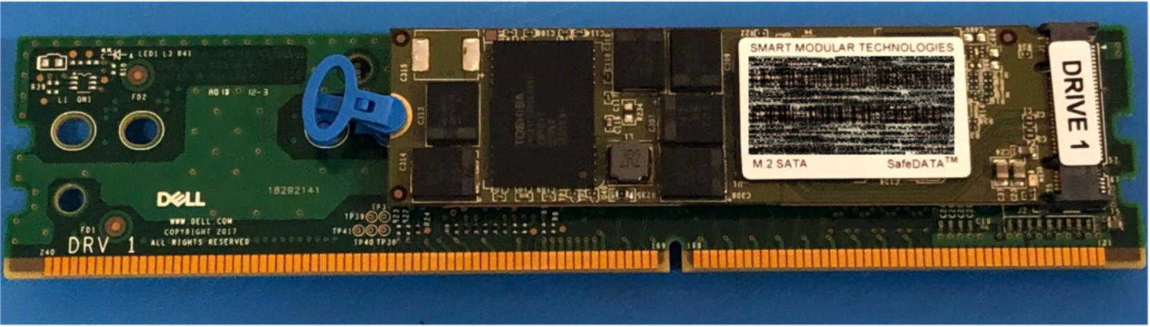
Figure 13. Internal M.2 boot module
Fan modules
PowerStore uses fan modules (cooling modules) to provide cool airflow to the node interior to ensure that the internal components remain at optimal operating temperatures. Each node contains seven redundant fan modules that are connected to the motherboard within the node. A node can tolerate a single fan module fault, and the surviving fans increase their speed to compensate for the faulted module. If two fan modules fault within the same node, the node performs a protective thermal shutdown. A protective thermal shutdown gracefully powers off the node, and any resource fails over to the surviving node.
Figure 14. Fan module
Battery backup unit
If system power is lost, the battery backup unit (BBU) provides power to the NVRAM drive slots and the baseboard management controller (BMC). This action allows the NVRAM drive drives to vault their volatile data to nonvolatile storage within the same drive and persist the information. Once the NVRAM drives have completed their vault, the BMC powers off the system. The BBU in node A provides power for drive slots 21 and 23. The BBU in node B provides power for drive slots 22 and 24. The NVRAM drives are in mirrored sets consisting of drives in slots 23 and 24. If the PowerStore model supports four NVRAM drives, there is another mirrored set in slots 21 and 22. The node BBUs are configured so that both BBUs power each NVRAM mirrored pair, ensuring that there is no single point of failure. Each BBU contains sufficient charge to accommodate multiple back-to-back power failures. Once power is resumed, the BBUs gradually recharge.
Figure 15. Battery backup unit
DIMMs
Each node contains 24 DDR4 DIMM slots used for DRAM, which are populated in different configurations that are based on the PowerStore model. All host data is written to the NVMe NVRAM drive from DRAM before the host is acknowledged to protect against data loss upon system power failure.
Figure 16. DIMM
Embedded module
Each node contains a single embedded module that has different connectivity components. The embedded module supports network connectivity for data storage, management and service access, cluster communication, and SAS connectivity to SAS expansion enclosures. The embedded module contains the following components:
- 4-port card
- Non-maskable interrupt (NMI) button
- Mini-SAS HD back-end ports
- System management port (1 GbE)
- Service port (1 GbE)
- USB port (Disabled by default in PowerStoreOS 3.6 & later)
There are two 4-port card options that are supported in the embedded module:
- 10 GbE BASE-T (4-port)
- 25/10 GbE optical/SFP+ and Twinax (4-port)
The 4-port card for the embedded module on node A must be the same 4-port card in the embedded module on node B. You can select the 4-port card configuration at the time of ordering but cannot change the configuration later. You must configure ports 0 and 1 with a link speed of at least 10 GbE on the 4-port card. This configuration ensures that intra-cluster traffic, which uses ports 0 and 1, has sufficient bandwidth. The 4-port card supports iSCSI, file, NVMe/TCP, replication, and import traffic.
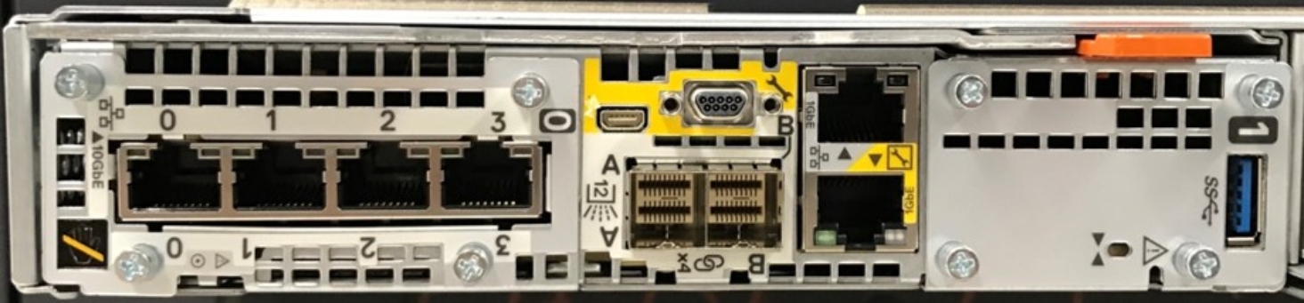
Figure 17. Embedded module with 10 GbE BASE-T 4-port card
I/O module
Each node on PowerStore systems can support up to two I/O modules that provide extra connectivity for the supported front-end protocols such as iSCSI, FC, file, NVMe/FC, NVMe/TCP, replication, and import. For the two nodes in a base enclosure, the I/O modules that are configured must match between nodes. During a node failure, matching I/O modules ensure that the peer node can begin servicing I/O using the mirrored I/O module.
PowerStore systems support the following I/O modules:
- 100 GbE optical/QSFP (2-port)
- 25/10 GbE optical/SFP+ and Twinax (4-port)
- 32/16/8/4 Gb Fibre Channel (4-port)
- 10 GbE BASE-T (4-port)
For more details about I/O modules, see I/O module.
Power supply
The PowerStore platform contains two power supply units (PSUs) in the base enclosure and offers PSUs with two wattage options that are based on the model. PowerStore 1000, PowerStore 3000, and PowerStore 5000 models support both the 1800W high-line and 2100W high-line PSUs. The PowerStore 7000 and PowerStore 9000 models support only the 2100W PSU. Do not select the 1800W PSU for environments with low-line power. For environments that only offer low-line power, you can use the 2100W PSU with a step-up transformer. The following table shows the PSU specifications for each PowerStore model.
Table 6. Power supplies
Model
Power supply wattage
Connector support
PowerStore 1000, 3000, 5000
1800 W1 or 2100 W2
1800 W: C13/14 or C13/20
2100 W: C19/C20
PowerStore 7000, 9000
2100 W2
2100 W: C19/20
1 Supports high-line power only
2 Supports high-line power and low-line power with step-up transformer
The following figure shows the supported connector types.
Figure 18. C19/C20, C13/C20, and C13/C14 connectors
A single power supply can power the entire base enclosure during a power supply failure. Power supplies can be replaced without having to remove the node. Power supplies are offered for AC power only.
Figure 19. 2100 W power supply
PowerStore 500
The PowerStore 500 base enclosure supports 25 all-NVMe 2.5-inch drives in a 2U chassis. The PowerStore 500 is introduced in the PowerStoreOS 2.0 release and requires PowerStoreOS 2.0 as a minimum supported software version.
The back of the base enclosure shows the nodes and their connectivity options. Each node has one embedded module and two I/O module slots (optional) for network connectivity. Each node has a dedicated 1 GbE BASE-T service port that can be used for on-site support access and initial configuration of the system. Each node also contains a second 1 GbE BASE-T port, which is used for management traffic. The embedded module of the node contains both of these embedded 1 GbE BASE-T ports.
For more information about the base enclosure and base enclosure components, see the PowerStore Hardware Information Guide for PowerStore 500 Models on Dell.com/powerstoredocs.
Drives
The base enclosure is an all-NVMe platform, capable of supporting NVMe SSD and NVMe SCM drives. You can populate slots 0 through 24 with NVMe SSD or NVMe SCM drives. PowerStore 500 systems use internal DRAM for write caching and do not support NVMe NVRAM drives like other PowerStore models.
PowerStore 500 systems can support one or more NVMe SCM drives mixed with NVMe SSD drives for metadata tiering. NVMe SCM drives provide lower latency than NVMe SSD drives and can improve system performance by storing metadata on these low-latency drives. On a system that contains both NVMe SCM and NVMe SSDs, the NVMe SCM drives are dedicated to metadata, and all user data is stored on NVMe SSD drives. PowerStore requires a minimum of six NVMe SSD drives for systems containing entirely NVMe SSD, or systems containing NVMe SSD supplemented with NVMe SCM. PowerStore requires a minimum of six NVMe SCM drives for system containing entirely NVMe SCM.
Starting in PowerStoreOS 3.0, PowerStore 500 model systems support up to three NVMe expansion enclosures per appliance for expanding capacity beyond the all-NVMe base enclosure with additional NVMe SSDs. NVMe expansion enclosures are not supported on systems that contain entirely NVMe SCM drives. NVMe expansion enclosures are supported on systems that have a mix of NVMe SSD and NVMe SCM in the base enclosure. On PowerStore 500 systems, ports 2 and 3 of the 4-port card are reserved for 25 GbE back-end connectivity to the NVMe expansion enclosure. For more details about PowerStore drives, see Drive model comparison.
Node
The purpose-built PowerStore 500 platform is powered by a single-socket upgraded Intel Xeon Processor. Each purpose-built PowerStore 500 system contains two nodes, which are used for high-availability and load-balancing purposes.
Each node is 1U and stacks vertically in the base enclosure, with the top node inverted. The bottom PowerStore node is node A, and the top PowerStore node is node B. Each node can access each drive through the midplane connection inside the base enclosure. Each node contains the following components:
- Internal M.2 boot module
- Fan modules
- Battery backup unit
- DIMMs
- Embedded module
- I/O module
- Power supply
Internal M.2 boot module
A single M.2 SATA device is located inside each node across from the CPU and DIMM complex. The M.2 device is 240 GB and is the primary boot device for the node. It stores the base operating system, log files, and vaulted cache data, and is used for general system operations.
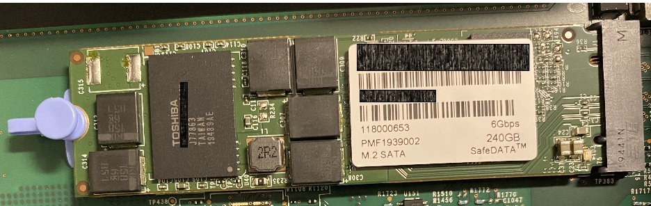
Figure 20. Internal M.2 boot module
Fan modules
Fan modules (cooling modules) provide cool airflow to the node interior to ensure that the internal components remain at optimal operating temperatures. Each node contains six redundant fan modules that are connected to the motherboard within the node. A node can tolerate a single fan module fault, and the surviving fans increase their speed to compensate for the faulted module. If two fan modules fault within the same node, the node performs a protective thermal shutdown. A protective thermal shutdown gracefully powers off the node, and any resource fails over to the surviving node.
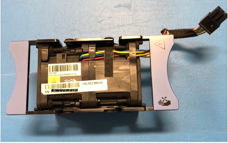
Figure 21. Fan module
Battery backup unit
If the system loses power, the battery backup unit (BBU) provides power to the node to enable cache vaulting. This feature allows the node to encrypt and back up dirty cache data during power loss from the system DRAM to the internal M.2 boot module. This BBU and vaulting process replaces the BBU and NVRAM self-vaulting process of the PowerStore 1000 to PowerStore 9200 models. After each node completes the vault of cached data, the node powers off. Each BBU contains sufficient charge to accommodate multiple back-to-back power failures. After power is resumed, the BBUs gradually recharge. The BBU is located between the third and fourth fan, in the middle of the enclosure.
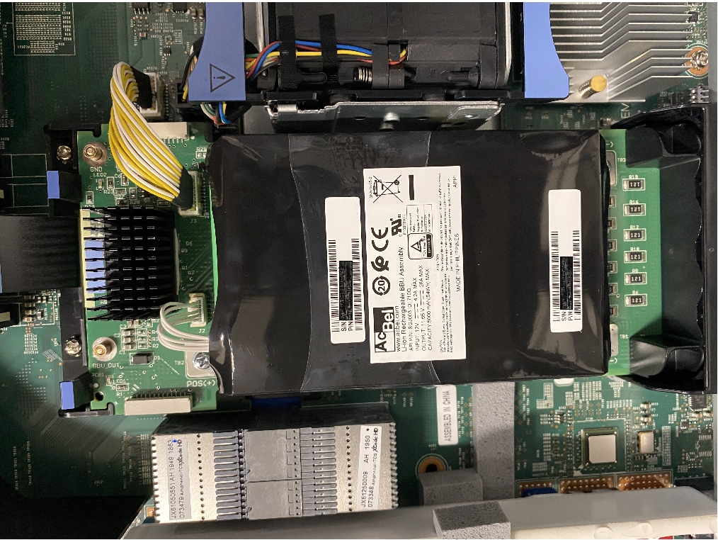
Figure 22. Battery backup unit
DIMMs
Each PowerStore 500 node is configured with DDR4 DIMMs. To protect against data loss, all host data is mirrored to the peer node before the host is acknowledged. Each node is equipped with a BBU to vault cached data to the internal M.2 boot module upon system power failure. For more detail on the PowerStore 500 write caching architecture, see the document PowerStore: Data Efficiencies on the Dell Technologies PowerStore Info Hub.
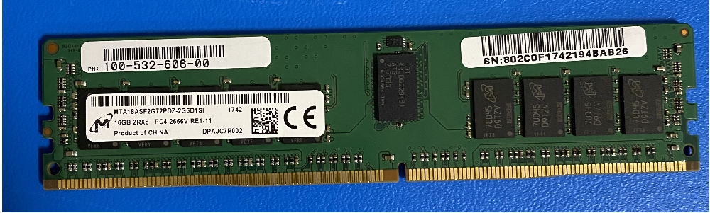
Figure 23. DIMM
Embedded module
Each node contains a single embedded module that has different connectivity components. The embedded module supports network connectivity for data storage, management and service access, cluster communication, and NVMe expansion shelf connectivity. The embedded module contains the following components:
- 25/10 GbE optical/SFP+ and Twinax 4-port card (optional)
- 10 GbE optical/SFP+ and TwinAx 2-port card
- Mini-SAS HD back-end ports1
- System management port (1 GbE)
- Service port (1 GbE)
1 Mini-SAS HD back-end ports have been removed from PowerStore 500 systems purchased after the release of PowerStoreOS 3.2.
The 4-port card is optional, and you can select it at the time of ordering. The 4-port card is required to support unified deployment mode (file services) and clustering with other appliances. If you do not select a 4-port card, you can deploy the system only in block-optimized mode. For more information about the deployment modes, see Deployment modes.
If you configure the 4-port card for the embedded module on node A, you must also configure a 4-port card on node B. You cannot add or remove the 4-port card after you complete the initial configuration. If you select a 4-port card, you must configure ports 0 and 1 with a link speed of at least 10 GbE on the 4-port card. This configuration ensures that intra-cluster traffic, which uses ports 0 and 1, has sufficient bandwidth. Ports 0 and 1 support file, iSCSI, NVMe/TCP, replication, and import. Ports 2 and 3 of the 4-port card are only supported for back-end connectivity with the NVMe expansion enclosures.
You can use the embedded 2-port card for front-end file, iSCSI, NVMe/TCP, replication, and import. This 2-port card is a fixed 10 GbE optical card that comes standard on all PowerStore 500 systems. The 2-port card supports SFPs and passive Twinax running at 10 GbE speeds.
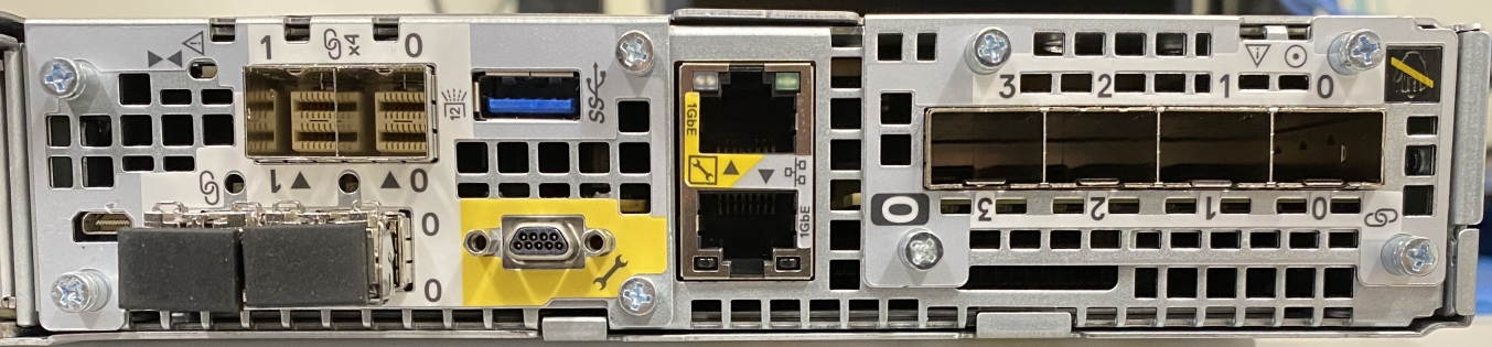
Figure 24. Embedded module with 4-port card
I/O module
Each node on PowerStore 500 systems can support up to two I/O modules that provide extra connectivity. For the two nodes in a base enclosure, the I/O modules that are configured must match between nodes. During a node failure, matching I/O modules ensure that the peer node can begin servicing I/O using the mirrored I/O module.
PowerStore 500 systems support the following I/O modules:
- 25/10 GbE optical/SFP+ and Twinax (4-port)
- 32/16/8/4 Gb Fibre Channel (4-port)
- 10 GbE BASE-T (4-port)
For more details about I/O modules, see I/O module.
Power supply
The PowerStore 500 platform offers either AC- or DC-powered power supply units (PSUs). The base enclosure comes with two PSUs, one per node, and the PSU models must match between nodes.
The 1450 W PSU supports high-line and low-line AC power and C13/C20 or C13/C14 connectors. The following figure shows the supported connector types.
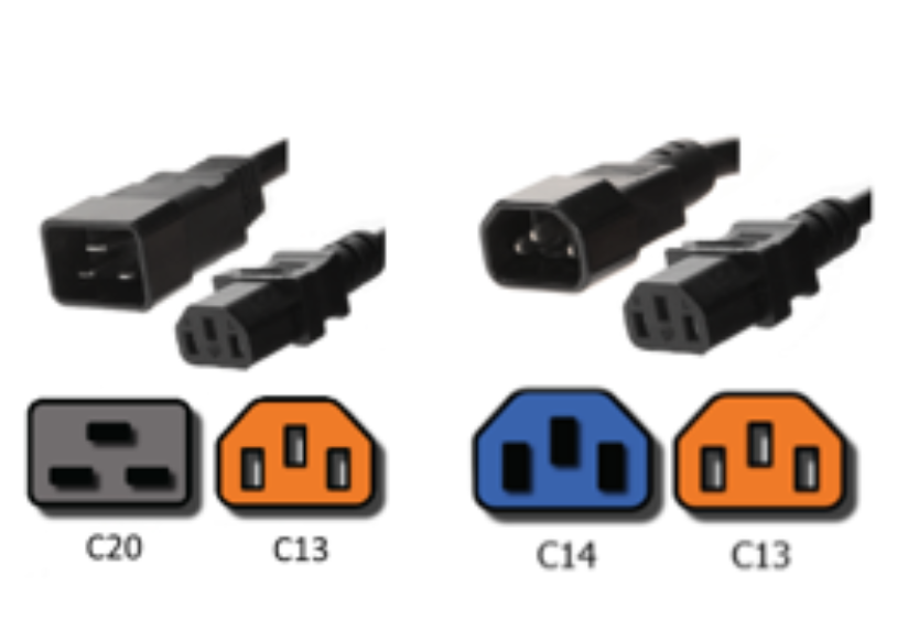
Figure 25. C13/C20 and C13/C14 connectors
The 1100 W PSU supports –48V DC power using a Positronic connector and requires PowerStoreOS 2.1 or greater. You can select either AC or DC power at the time of ordering, but you cannot convert a PowerStore 500 system from AC to DC, or from DC to AC, PSUs.
A single power supply can power the entire base enclosure during a power-supply failure. You can replace the power supplies without removing the node.
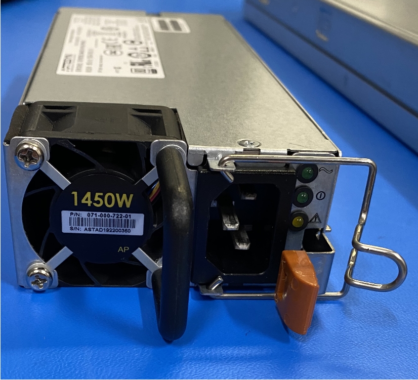
Figure 26. 1450 W power supply