
PowerStore 500
PowerStore 500
-
Writes
Unlike the PowerStore 1000, 1200, 3000, 3200, 5000, 5200, 7000, 9000, 9200 appliances, the PowerStore 500 does not support NVMe NVRAM drives. Instead, the system uses each Node DRAM memory as a write caching layer to temporarily store data before it is passed through the deduplication and compression process. Figure 4 is a high-level diagram of a write I/O entering a PowerStore 500 system and the steps that are taken before acknowledging the host.
Step 1 depicts a write request entering Node B. The information is stored within the Node DRAM Memory, as shown in Step 2. The information is then analyzed to determine what type of I/O it is, what resource it is intended for, and the location within the resource being updated or requested.
If the I/O is determined to be a write, the information is then mirrored to the peer Node DRAM Memory, as depicted by Step 3. A full copy of the data and information about the request is passed through the internal connections between the nodes in the system. After the data is mirrored to the peer node, the host is acknowledged that the write has been persisted on the system, as shown in Step 4. The data is passed through the deduplication and compression algorithms at a later time.
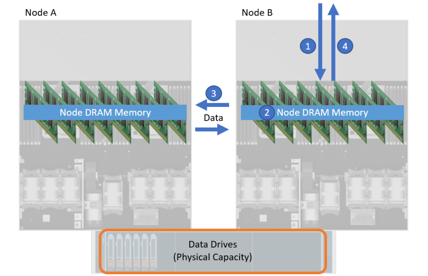
Figure 4. A write I/O entering PowerStore 500 model system
Within a PowerStore 500 appliance, Battery Backup Units (BBUs) are used to protect the contents of the appliance’s volatile DRAM Memory. If power is interrupted to the system, the BBUs ensure the cached contents within DRAM memory are safely persisted to a nonvolatile M.2 SATA device contained within the node. When all data is protected, the system finishes its graceful power down procedure. When power is resumed, cached data is restored to DRAM Memory during the bootup process, thus preserving the previous cache contents. Normal operations continue and data is passed through deduplication and compression algorithms at a later time.