
PowerStore 1000 to 9200
PowerStore 1000 to 9200
-
The following sections describe how PowerStore system models 1000 to 9200 provide inline data efficiencies.
Write path background information
Before the data efficiency techniques of PowerStore 1000, 1200, 3000, 3200, 5000, 5200, 7000, 9000, and 9200 are discussed, the system design and data path must be reviewed to explain how these PowerStore systems provide inline data efficiencies. Figure 1 shows a high-level diagram of the components within these systems that are part of the data path. In this figure, node A and node B are shown side-by-side for demonstration purposes. Within the system, DRAM memory is used as a caching layer as data enters and exits the system. All data passes through and interacts with DRAM memory. How the data interacts with DRAM memory depends if the I/O is a read or a write I/O. How a read and write I/O passes through DRAM memory is explained later in this section.
Another major component of the data path are the data drives. The drives, which are outlined in orange in Figure 1, provide the physical capacity to the system to store data. If additional enclosures are attached to the system, they similarly add to the usable capacity of the system. Within PowerStore, any data drives in a PowerStore 1000 to 9200 system contribute to a single, large, usable capacity. Drives used for the NVMe NVRAM cache, or SCM drives dedicated for metadata tiering, are excluded from the usable capacity of the system. This space is shared for all resources within the system.
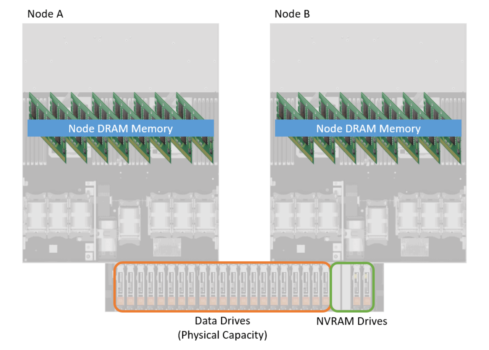
Figure 1. Data path components in PowerStore 1000 to 9200 models
PowerStore 1000 to 9200 model systems include NVRAM drives, which are part of the PowerStore system’s data path. These drives are circled in green in the lower right of the above figure. The NVRAM drives are hard drives that are located in the far-right slots of the base enclosure of the appliance. Depending on the system model, these two or four NVRAM drives are used as an additional write I/O cache location for protection purposes within the system. As writes enter the system, a copy of each write is placed in DRAM memory and the NVRAM drives before the host is acknowledged that the write has been saved within the system. After the host is acknowledged, data is passed through the deduplication and compression logic before being saved to the data drives of the system.
The Figure 2 shows more information about the NVRAM drives. As mentioned previously, each appliance contains either two or four NVRAM drives, which are physically located in the far-right drive slots of the base enclosure of the appliance. If the system only contains two NVRAM drives, they are populated in drive slots 23 and 24. If four NVRAM drives are present, then slots 21 through 24 are occupied. NVRAM drives are deployed in mirrored pairs to guard against a single drive failure. Drives 21 and 22 are configured in a mirrored pair, as well as drives 23 and 24. During an NVRAM drive failure, write caching continues to be enabled, and the mirrored pair is reestablished when the faulted drive is replaced.
The appliance also provides battery backup to the NVRAM drives using internal batteries within each node. Slots 21 and 23 are connected to Node A’s internal battery device, while Node B provides power to slots 22 and 24. Battery backup is required as NVRAM drives contain both volatile and nonvolatile media. The volatile media provides fast access speeds, and is used as a backup location for write caching within the system while the appliance is under normal operation. If power to the appliance is interrupted or the system is powered off, the volatile write cache is destaged to the nonvolatile media within the NVRAM drive. When the write cache information is safely stored, power is removed from the drives and the system completes its shutdown operation. The NVRAM design and operations replace the need to protect the contents of DRAM write cache.
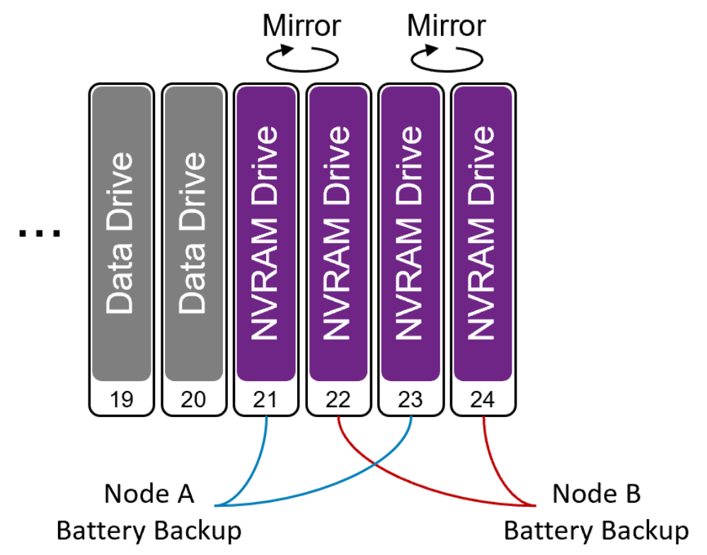
Figure 2. NVRAM drives in PowerStore
Writes
All writes entering a PowerStore 1000, 1200, 3000, 3200, 5000, 5200, 7000, 9000, and 9200 appliance follow the same data path, regardless of the resource type. Figure 3 displays a high-level diagram of a write I/O entering the system. Figure 3 also shows the steps that are taken to store the information within the system before acknowledging the host.
Step 1 depicts an I/O entering Node B. The I/O is saved within the node DRAM memory and is analyzed to determine what type of I/O it is, what resource it is intended for, and the location within the resource being updated or requested.
If the I/O is determined to be a write, the information is stored within write cache in the Node DRAM Memory (Step 2). A copy of the write is also written to the NVRAM drives, shown as Step 3 in Figure 3. As mentioned previously, the appliance NVRAM drives are used as an additional write cache location within the system for redundancy purposes. Each NVRAM drive is also dual-ported, meaning that each node has access to the drives through physical internal connections and the information that is contained in them. If required, the peer node can access the data as needed.
Step 4 occurs for each write I/O that enters the system. Information is passed between the nodes to update the peer that a new write has been received and that it has the newest copy of the data for the resource. This token includes information about the I/O such as what resource was updated, the address within the resource that was updated, and the location where the I/O was saved to within the write cache. If the information is requested through the peer node, the node can access the data within the NVRAM drives by its own internal channels.
The last step (Step 5) in completing the I/O is to acknowledge the host. After the information is safely stored within the appliance and all other actions are complete, the host is acknowledged. The data is passed through the deduplication and compression algorithms at a later time.
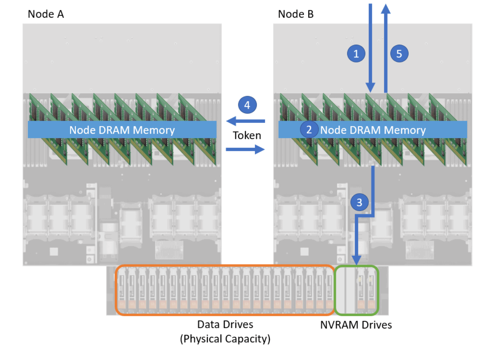
Figure 3. A write I/O entering PowerStore 1000 to 9200 model system