
Architecture
Architecture
-
OneFS data reduction offers both inline data compression and inline deduplication, and the supporting OneFS architecture is consists of the following principal components:
- Data Reduction Platform
- Compression Engine and Chunk Map
- Zero block removal phase
- Deduplication In-memory Index and Shadow Store Infrastructure
- Data Reduction Alerting and Reporting Framework
- Data Reduction Control Path
The inline data reduction control path consists of the OneFS command line interface (CLI) and RESTful platform API and is responsible for managing the configuration and reporting of the feature.
In-line data reduction platform
In-line data reduction is supported on the Dell PowerScale F910, F900, F710, F600, F210, and F200 SSD nodes, PowerScale H700/7000 and A300/3000 node, and the Isilon F810 and H5600 platforms.
The specific OneFS versions required to support a cluster or node pool with the following characteristics include:
- OneFS 8.2.1 or later for an F810 node pool.
- OneFS 8.2.2 or later for an H5600 node pool.
- OneFS 9.0 or later for an F600 or F200 node pool.
- OneFS 9.2 or later for an F900 node pool.
- OneFS 9.2.1 or later for an H700, H7000, A300, or A3000 node pool.
- OneFS 9.3 or later for PowerScale P100 and B100 accelerator nodes.
- OneFS 9.7 or later for an F710 or F210 node pool.
- OneFS 9.8 or later for an F910 node pool.
Unlike the other platforms above, each F810 node includes a data reduction hardware off-load adapter. This adapter off-loads certain tasks from the CPU. Specifically, data compression and inflation are transparently performed by the off-load adapter with minimal latency, avoiding the need for consuming a node’s expensive CPU and memory resources.
Each F810 node’s data reduction off-load adapter contains an FPGA chip, which is dedicated to the compression of data received by means of client connections to the node. These cards reside in the backend PCI-e slot in each of the four nodes. The two Ethernet ports in each adapter are used for the node’s redundant backend network connectivity.
In-line data reduction workflow
Data from network clients is accepted as is and makes its way through the OneFS write path until it reaches the BSW engine, where it is broken up into individual chunks. The inline data reduction write path consists of three main phases:
- Zero Block Removal
- In-line Deduplication
- In-line Compression
If both inline compression and deduplication are enabled on a cluster, zero block removal is performed first, followed by dedupe, and then compression. This order allows each phase to reduce the scope of work each subsequent phase.

Figure 3. In-line data reduction workflow
Zero block removal
The inline data reduction zero block removal phase detects blocks that contain only zeros and prevents them from being written to disk. This both reduces disk space requirements and avoids unnecessary writes to SSD, resulting in increased drive longevity.
Zero block removal occurs first in the OneFS inline data reduction process. As such, it has the potential to reduce the amount of work that both inline deduplication and compression need to perform. The check for zero data does incur some overhead. However, for blocks that contain non-zero data the check is terminated on the first non-zero data found, which helps to minimize the impact.
The following characteristics are required for zero block removal to occur:
- A full 8KB block of zeroes
- A partial block of zeroes being written to a sparse or prealloc block
The write will convert the block to sparse if not already. A partial block of zeroes being written to a non-sparse, non-preallocated block will not be zero eliminated.
In-line deduplication
While OneFS has offered a native file system deduplication solution for several years, until OneFS 8.2.1 this was always accomplished by scanning the data after it has been written to disk, or post-process. With inline data reduction, deduplication is now performed in real time, as data is written to the cluster. Storage efficiency is achieved by scanning the data for identical blocks as it is received and then eliminating the duplicates.
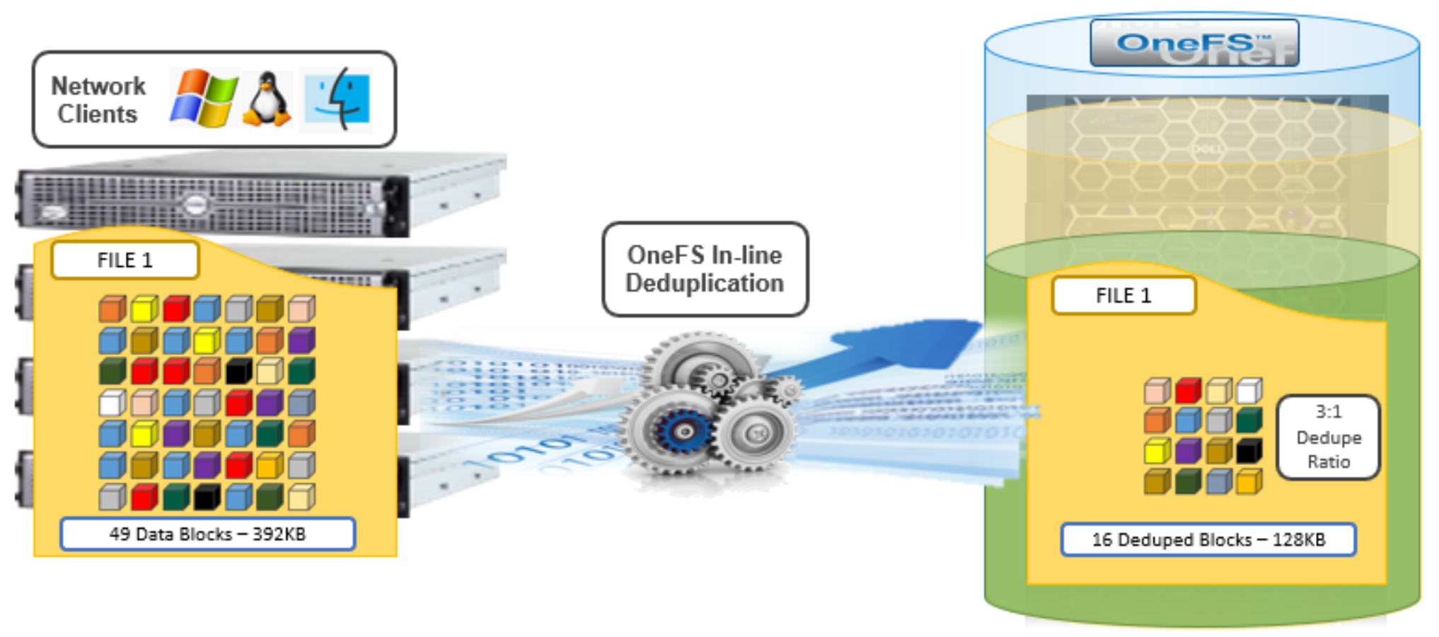
Figure 4. OneFS inline deduplication
When a duplicate block is discovered, inline deduplication moves a single copy of the block to a special set of files known as shadow stores. OneFS shadow stores are file system containers that allow data to be stored in a shareable manner. As such, files on OneFS can contain both physical data and pointers, or references, to shared blocks in shadow stores.
Shadow stores were first introduced in OneFS 7.0, initially supporting OneFS file clones, and there are many overlaps between cloning and deduplicating files. The other main consumer of shadow stores is OneFS Small File Storage Efficiency. This feature maximizes the space utilization of a cluster by decreasing the amount of physical storage required to house the small files that comprise a typical healthcare dataset.
Shadow stores are similar to regular files but are hidden from the file system namespace, so cannot be accessed using a pathname. A shadow store typically grows to a maximum size of 2GB, which is around 256K blocks, with each block able to be referenced by 32,000 files. If the reference count limit is reached, a new block is allocated, which may or may not be in the same shadow store. Also, shadow stores do not reference other shadow stores. And snapshots of shadow stores are not permitted because the data contained in shadow stores cannot be overwritten.
When a client writes a file to a node pool configured for inline deduplication on a cluster, the write operation is divided up into whole 8KB blocks. Each of these blocks is then hashed and its cryptographic ‘fingerprint’ compared against an in-memory index for a match. At this point, one of the following operations will occur:
- If a match is discovered with an existing shadow store block, a byte-by-byte comparison is performed. If the comparison is successful, the data is removed from the current write operation and replaced with a shadow reference.
- When a match is found with another LIN, the data is written to a shadow store instead and replaced with a shadow reference. Next, a work request is generated and queued that includes the location for the new shadow store block, the matching LIN and block, and the data hash. A byte-by-byte data comparison is performed to verify the match and the request is then processed.
- If no match is found, the data is written to the file natively and the hash for the block is added to the in-memory index.
In order for inline deduplication to be performed on a write operation, the following conditions need to be true:
- In-line dedupe must be globally enabled on the cluster.
- The current operation is writing data (that is, not a truncate or write zero operation).
- The ‘no_dedupe’ flag is not set on the file.
- The file is not a special file type, such as an alternate data stream (ADS) or an EC (endurant cache) file.
- Write data includes fully overwritten and aligned blocks.
- The write is not part of a ‘rehydrate’ operation.
- The file has not been packed (containerized) by SFSE (small file storage efficiency).
OneFS inline deduplication uses the 128-bit CityHash algorithm, which is both fast and cryptographically strong. This contrasts with OneFS’ post-process SmartDedupe, which uses SHA-1 hashing.
Each F910, F900, F810, F710, F600, F210, F200, F700/7000, H5600, or A300/3000 node in a cluster with inline dedupe enabled has its own in-memory hash index that it compares block ‘fingerprints’ against. The index lives in system RAM and is allocated using physically contiguous pages and accessed directly with physical addresses. This avoids the need to traverse virtual memory mappings and does not incur the cost of translation lookaside buffer (TLB) misses, minimizing deduplication performance impact.
The maximum size of the hash index is governed by a pair of sysctl settings, one of which caps the size at 16GB, and the other which limits the maximum size to 10% of total RAM. The strictest of these two constraints applies. While these settings are configurable, the recommended best practice is to use the default configuration. Any changes to these settings should only be performed under the supervision of Dell support.
Since inline dedupe and SmartDedupe use different hashing algorithms, the indexes for each are not shared directly. However, the work performed by each dedupe solution can be leveraged by each other. For instance, if SmartDedupe writes data to a shadow store, when those blocks are read, the read hashing component of inline dedupe will see those blocks and index them.
When a match is found, inline dedupe performs a byte-by-byte comparison of each block to be shared to avoid the potential for a hash collision. Data is prefetched prior to the byte-by-byte check and then compared against the L1 cache buffer directly, avoiding unnecessary data copies and adding minimal overhead. Once the matching blocks have been compared and verified as identical, they are then shared by writing the matching data to a common shadow store and creating references from the original files to this shadow store.
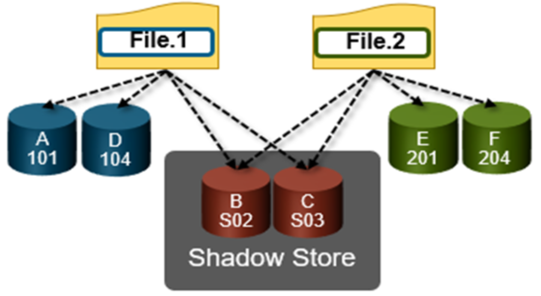
Figure 5. OneFS duplicate block sharing
In-line dedupe samples every whole block written and handles each block independently, so it can aggressively locate block duplicity. If a contiguous run of matching blocks is detected, inline dedupe will merge the results into regions and process them efficiently.
In-line dedupe also detects dedupe opportunities from the read path, and blocks are hashed as they are read into L1 cache and inserted into the index. If an existing entry exists for that hash, inline dedupe knows there is a block sharing opportunity between the block it just read and the one previously indexed. It combines that information and queues a request to an asynchronous dedupe worker thread. As such, it is possible to deduplicate a data set purely by reading it all. To help mitigate the performance impact, the hashing is performed out-of-band in the prefetch path, rather than in the latency-sensitive read path.
In-line compression
Under the hood, the F810 nodes use an FPGA-based hardware offload engine resident on the backend PCI-e network adapter to perform real-time data compression. This occurs as files are written to from a node in the cluster over a connected client session. Similarly, files are reinflated on demand as they are read by clients.
On top of the FPGA, the OneFS hardware off-load engine uses a proprietary implementation of DEFLATE with the highest level of compression, while incurring minimal to no performance penalty for highly compressible datasets.
The compression engine consists of three main components:
Table 4. OneFS data reduction engine components
Engine component
Description
Search Module
LZ77 search module analyzes inline file data chunks for repeated patterns.
Encoding Module
Performs data compression (Huffman encoding) on target chunks.
Decompression Module
Regenerates the original file from the compressed chunks.
Note: Because they reside on the same card, the data compression engine shares PCI-e bandwidth with the node’s backend Ethernet interfaces. In general, there is plenty of bandwidth available. A best practice is to run highly compressible datasets through the F810 nodes with compression enabled. However, it is not advisable to run non-compressible datasets with compression enabled.
OneFS provides software-based compression for the F910, F900, F710, F600, F210, F200, F700/7000, H5600, and A300/3000 platforms. Compression in software is also used as fallback in the event of an F810 hardware failure, and in a mixed cluster for use in nodes without a hardware offload capability. Both hardware and software compression implementations are DEFLATE compatible.
Compression file chunking
When a file is written to OneFS using inline data compression, the file’s logical space is divided up into equal sized chunks called compression chunks. Compaction is used to create 128KB compression chunks, with each chunk consisting of sixteen 8KB data blocks. This is optimal since 128KB is the same chunk size that OneFS uses for its data protection stripe units, providing simplicity and efficiency, by avoiding the overhead of additional chunk packing.
For example, consider the following 128KB chunk:
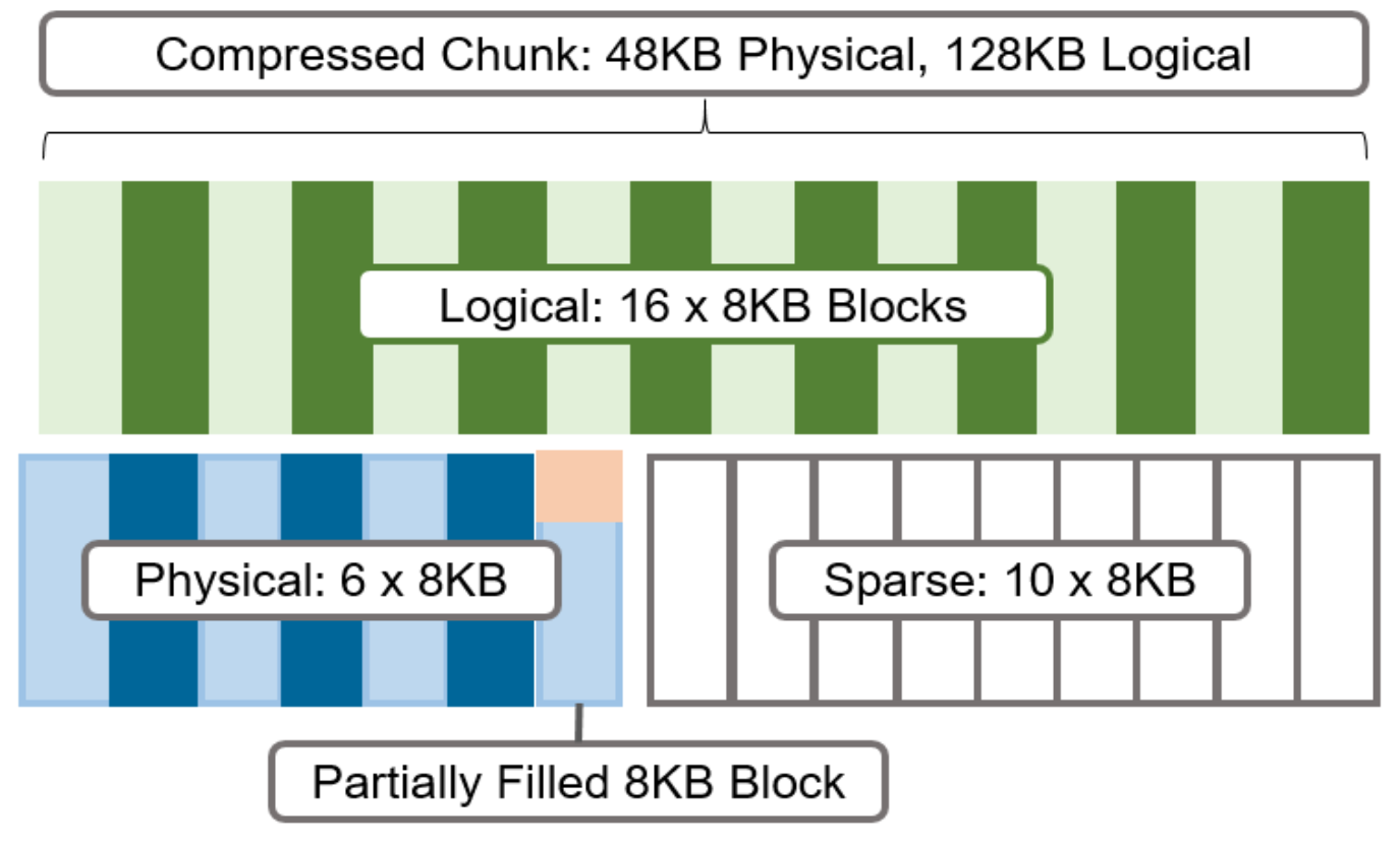
Figure 6. Compression chunks and OneFS transparent overlay
After compression, this chunk is reduced from sixteen to six 8KB blocks in size. This means that this chunk is now physically 48KB in size. OneFS provides a transparent logical overlay to the physical attributes. This overlay describes whether the backing data is compressed or not and which blocks in the chunk are physical or sparse, such that file system consumers are unaffected by compression. As such, the compressed chunk is logically represented as 128KB in size, regardless of its actual physical size. The orange sector in the figure above represents the trailing, partially filled 8KB block in the chunk. Depending on how each 128KB chunk compresses, the last block may be under-utilized by up to 7KB after compression.
Efficiency savings must be at least 8KB (one block) for compression to occur, otherwise that chunk or file will be passed over and remain in its original, uncompressed state. For example, a file of 16KB that yields 8KB (one block) of savings would be compressed. Once a file has been compressed, it is then protected with Forward Error Correction (FEC) parity blocks, reducing the number of FEC blocks and therefore providing further overall storage savings.
Compression chunks will never cross node pools. This avoids the need to decompress or recompress data to change protection levels, perform recovered writes, or otherwise shift protection-group boundaries.
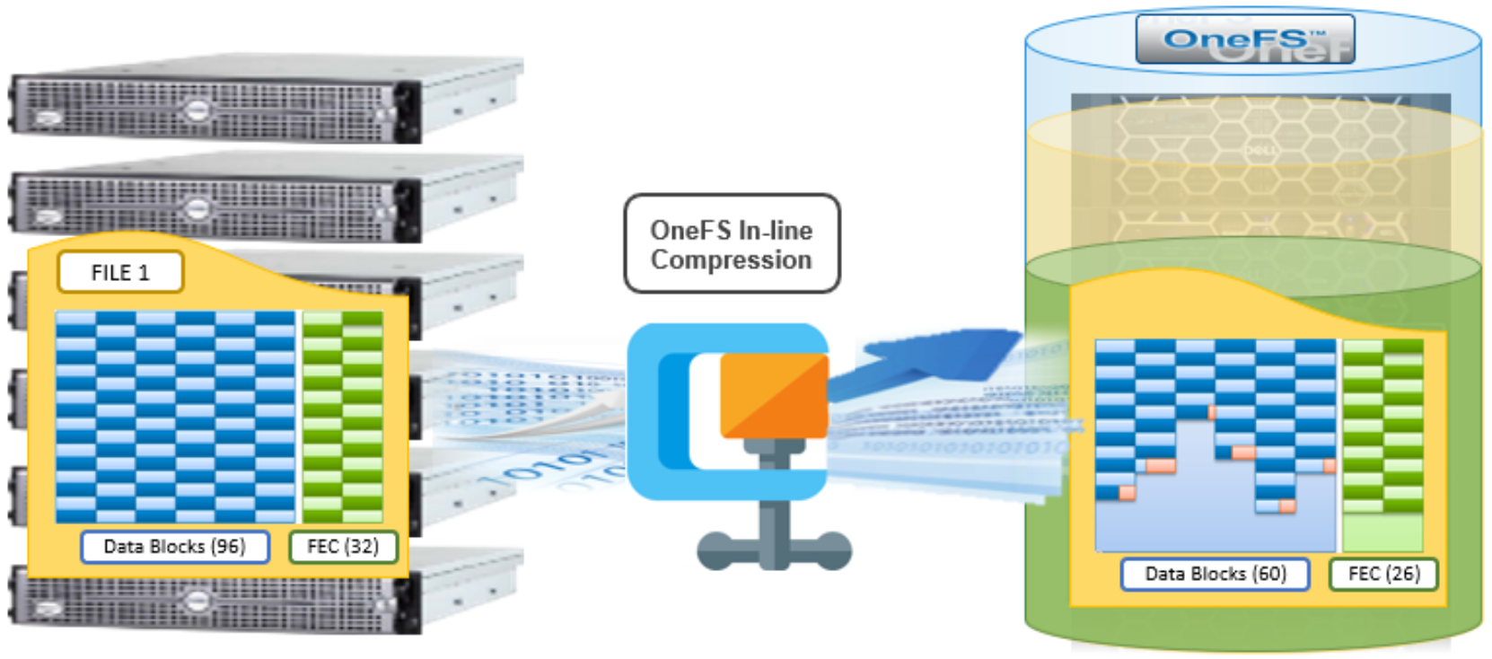
Figure 7. OneFS inline compression
In the figure above, a 768KB file (file1) is written from a Windows client to an F810 cluster. After passing through the OneFS inline compression engine, the logical data footprint of that file is reduced from ninety-six to sixty 8KB blocks, across six chunks. This is represented by the blue data blocks. The file is then FEC protected using twenty-six parity blocks, shown in green.
In-line data reduction write path
In a PowerScale cluster, data, metadata, and inodes are all distributed across multiple drives on multiple nodes. When reading or writing to the cluster, a client is directed by SmartConnect to the desired protocol head on a particular node, or initiator. This node then acts as the ‘captain’ for the operation, performing the chunking and data compression, orchestrating the layout of data and metadata, the creation of erasure codes, and the normal operations of lock management and permissions control.
Take for example a four node F810 cluster. A Windows client connects to the top half, or initiator, on node 1 to write a file. Once the SMB session is established and write request granted, the client begins to send the file data across the front-end network to the cluster where it is initially buffered in the coalescer, or OneFS write cache. The purpose of the coalescer is to build up a large contiguous range of data that will make the write operation more efficient.
When the coalescer is flushed, data chunks, typically sized on protection group boundaries, are passed through the data reduction pipeline. First, if inline dedupe is enabled, the incoming data is scanned for zero block removal and deduplication opportunities. When found, any zero blocks are stripped out and any matching blocks are deduplicated. Next, chunks that meet the ‘compressibility’ criteria described above are compressed by the FPGA. Finally, the initiator executes its ‘write plan’ for the file data, optimizing for layout efficiency and the selected protection policy, and the chunks/stripes are written to SSDs on the bottom half of the participant nodes.
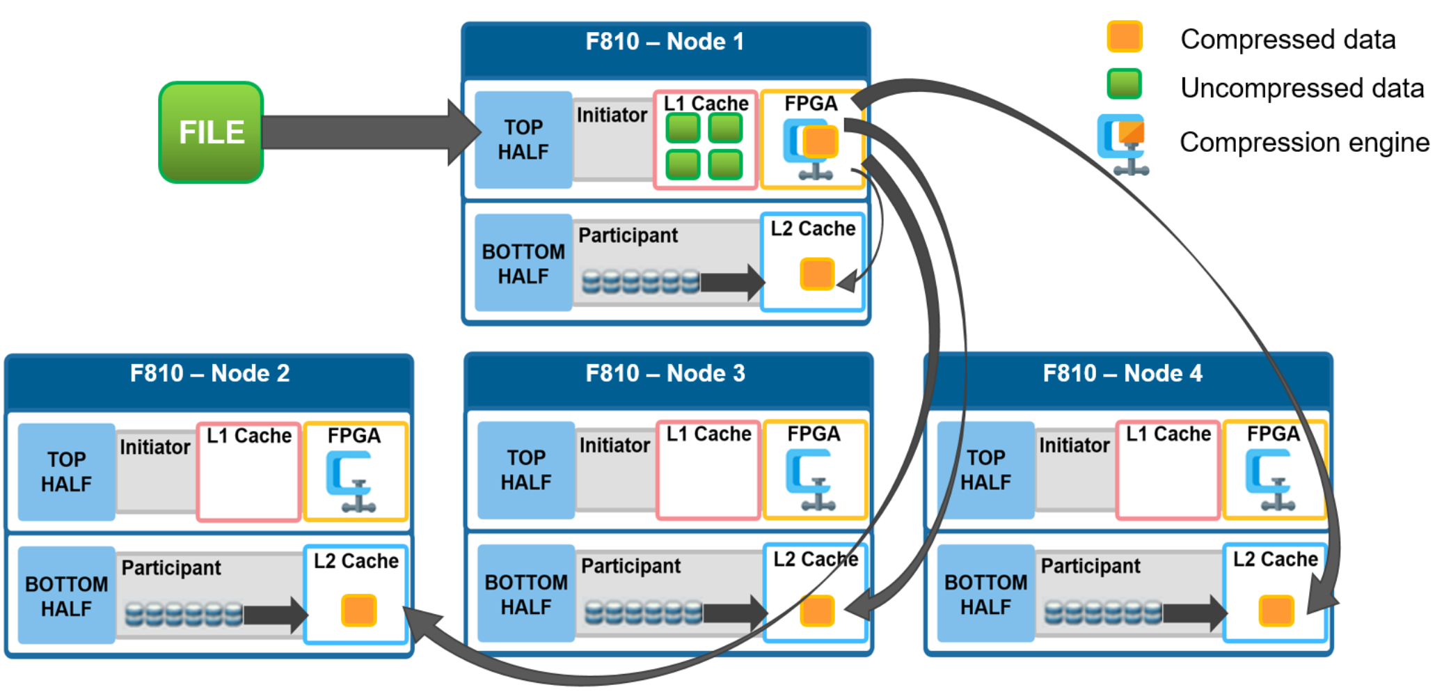
Figure 8. File writes with compression
OneFS stripes data across all nodes—and not simply across disks—and protects the files, directories, and associated metadata by software erasure-code or mirroring technology. Erasure coding can provide beyond 80% efficiency on raw disk with five nodes or more, and on large clusters can even do so while providing quadruple-level redundancy. For any given file, the stripe width is the number of nodes (not disks) that a file is written across. For example, on the 4-node F810 cluster above with the recommended +2d:1n protection level, OneFS will use a stripe width of 8 and protection level of 6+2, where each node is used twice, that is: two data stripe units are written to each of three nodes, and two FEC units to the remaining node.
For details about OneFS data protection, see the OneFS Technical Overview white paper.
In-line data reduction read path and caching integration
In the diagram below, an NFS client attaches to node 1 and issues a read request for a file. Node 1, the captain, gathers all the chunks of data from the various nodes in the cluster and presents it in a cohesive way to the requesting client. Since the file’s data has been stored in a compressed form on nodes’ SSDs, node 1 needs to gather all the constituent chunks and decompress the data so the file can be sent across the wire to the client in its original form.
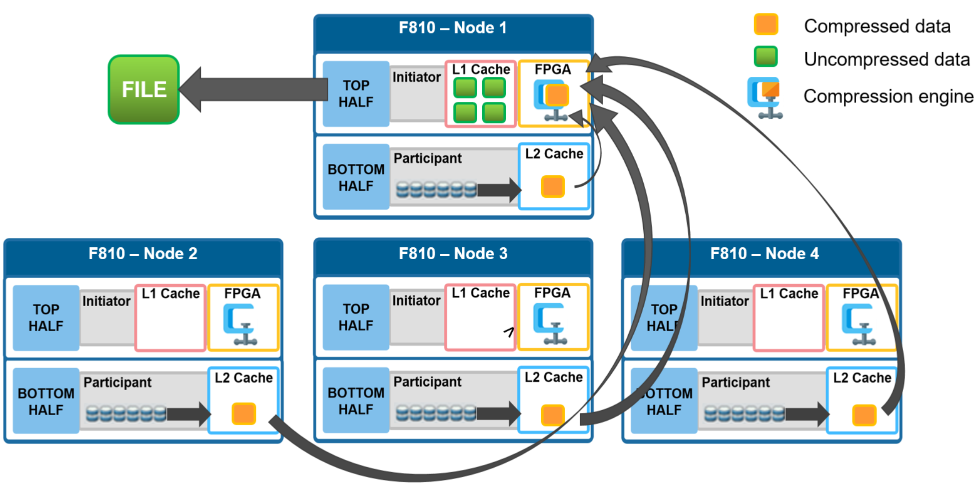
Figure 9. File reads with compression
During this read process, the L2 read cache on the participant nodes (nodes 2 through 4) is populated with the compressed data chunks that are sent to node 1. This means that any additional read requests for this file can be served straight from low latency cache, rather than reading again from the drives. This process both accelerates read performance and reduces wear on the SSDs.
To support OneFS inline compression, a node’s L1, or client-side, read cache is divided into separate address spaces so that both the on-disk compressed data and the logical uncompressed data can be cached. The address space for the L1 cache is already split for data and FEC blocks, so a similar technique is used to divide it again. Data in the uncompressed L1 cache is fed from data in the compressed L1 cache which, in turn, is fed from disk.
OneFS prefetch caching has also been enhanced to accommodate compressed data. Since reading part of a compressed chunk results in the entire compression chunk being cached, it will effectively mean that prefetch requests are rounded to compression chunk boundaries. Since a prefetch request is not complete until the uncompressed data is available in cache, the callback used for prefetch requests performs the decompression.