
Example 2: Network design with 252 PowerScale nodes
Example 2: Network design with 252 PowerScale nodes
-
This example includes a proposed solution of 252 PowerScale nodes in the cluster using 64-port switches for the leaf-spine deployment:
Configuration: 252 performance-only nodes (100 GbE back end)
Assumptions or requirements: All nodes connect to the back-end leaf switch on the same rack, and only uplink cables to spine switches connect to a different rack.
Leaf switch/ports
Spine switch/ports
L1 Ports 1-8
S1 Ports 1-8
L1Ports 9-16
S2 Ports 1-8
L1Ports 17-24
S3 Ports 1-8
L1 Ports 25-32
S4 Ports 1-8
L2 Ports 1-8
S1 Ports 9-16
L2 Ports 9-16
S2 Ports 9-16
L2 Ports 17-24
S3 Ports 9-16
L2 Ports 25-32
S4 Ports 9-16

L8 Ports 1-8
S1 Ports 57-64
L8 Ports 9-16
S2 Ports 57-64
L8 Ports 17-24
S3 Ports 57-64
L8 Ports 25-32
S4 Ports 57-64
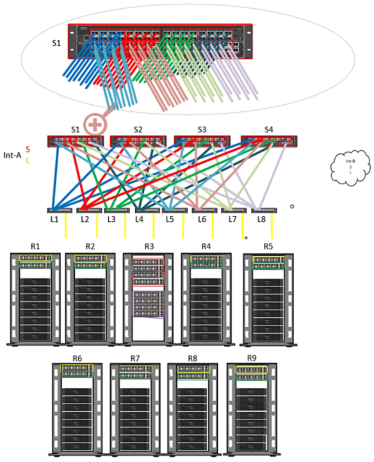
Figure 5. Sample configuration design of 252 nodes with 100 GbE back-end network
This example configuration includes the following:
- 24 Dell Z9264 switches (12 per side)
- 4 spine switches
- 8 leaf switches
- 512 QSFP28 100 Gb uplink cables (8 uplink cables per leaf)
- 512 QSFP+ or MPO back-end cables
- 512 Optics (if MPO cables used)
Note: Because these nodes are 100 GbE back end, they require more uplinks than 40 GbE back-end nodes. This example has 8 x 100 GbE uplinks per leaf.
Design considerations: To simplify and organize cabling, place your leaf switches accordingly (see Figure 5). As shown, two leaf switches from Int-a and two leaf switches from Int-b are spread across all racks except R3. No leaf switches are in R3, which contains only spine switches.
To provide resiliency from a single rack failure containing all the spine switches, a suggestion would be to locate all spine switches for int-A in one rack and all spine switches for int-B in another rack.