
Example 1: Network design with 252 PowerScale nodes
Example 1: Network design with 252 PowerScale nodes
-
This example includes a proposed solution of 252 PowerScale nodes in the cluster using 32-port switches for the leaf-spine deployment:
Configuration: 252 performance-only nodes (40 GbE back end)
Assumptions or requirements:
- Connect not only uplink cables but also downlink cables to nodes on a different rack.
- Due to limited rack space, the customer in this example requests to minimize space in the data center.
Leaf switch
Leaf Ports à Spine switch connection
L1
Port 1 and 2 à Spine switch 1, 2, 3, 4 and 5
L2
Port 3 and 4 à Spine switch 1, 2, 3, 4 and 5
L3
Port 5 and 6 à Spine switch 1, 2, 3, 4 and 5
L4
Port 7 and 8 à Spine switch 1, 2, 3, 4 and 5
L5
Port 9 and 10 à Spine switch 1, 2, 3, 4 and 5
Port 11 and 12 à Spine switch 1, 2, 3, 4 and 5
L7
Port 13 and 14 à Spine switch 1, 2, 3, 4 and 5
L8
Port 15 and 16 à Spine switch 1, 2, 3, 4 and 5
L9
Port 17 and 18 à Spine switch 1, 2, 3, 4 and 5
L10
Port 19 and 20 à Spine switch 1, 2, 3, 4 and 5
L11
Port 21 and 22 à Spine switch 1, 2, 3, 4 and 5
L12
Port 23 and 24 à Spine switch 1, 2, 3, 4 and 5
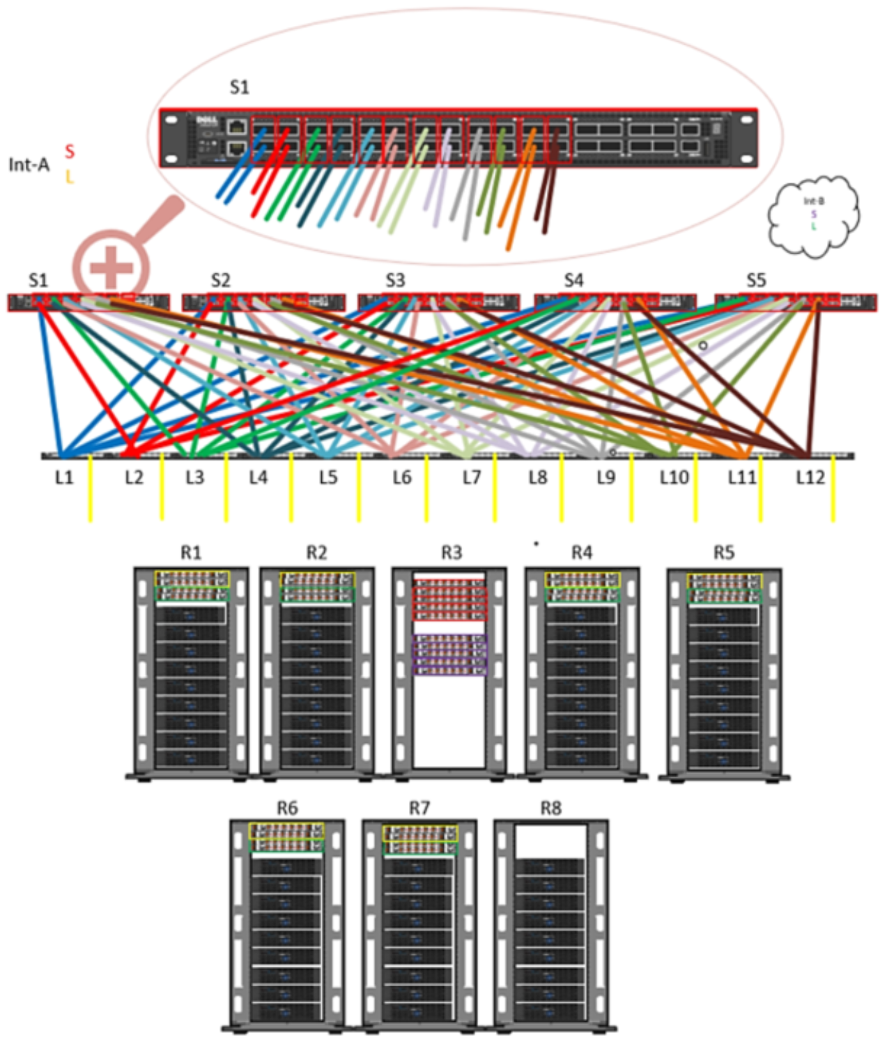
Figure 4. Sample configuration design of 252 nodes with 40 GbE back-end network
This example configuration includes the following:
- 34 Dell Networking Z9100 switches (17 per side)
- 5 spine switches
- 12 leaf switches
- 240 QSFP28 100 Gb uplink cables (10 uplink cables per leaf)
- 504 QSFP+ or MPO back-end cables
- 504 Optics (if MPO cables used)
Note: This example is accurate if you size all F600 systems with 40 GbE back-end connectivity.
Design considerations: To simplify and organize cabling, place your leaf switches accordingly (see Figure 4). As shown, two leaf switches from Int-a and two leaf switches from Int-b are spread across all racks except R8 and R3. No leaf switches are on R8 and R3, and the chassis on R8 must connect to a different rack.
To provide resiliency from a single rack failure containing all the spine switches, a suggestion would be to locate all spine switches for int-A in one rack and all spine switches for int-B in another rack.