
Cabling and networking
Cabling and networking
-
With copper cables (SFP+, QSFP, CX4, and so on) the maximum cable length is typically limited to 10 meters or less. After factoring in for dressing the cables to maintain some level of organization and proximity within the racks and cable trays, all the racks with PowerScale nodes need to be in close physical proximity to each other –either in the same rack row or close by in an adjacent row – or adopt a leaf-spine topology, with leaf switches in each rack.
If greater physical distance between nodes is required, support for multimode fiber (QSFP+, MPO, LC, and so on) extends the cable length limitation to 150 meters. This allows nodes to be housed on separate floors or on the far side of a floor in a datacenter if necessary. While solving the floor space problem, this does have the potential to introduce new administrative and management challenges.
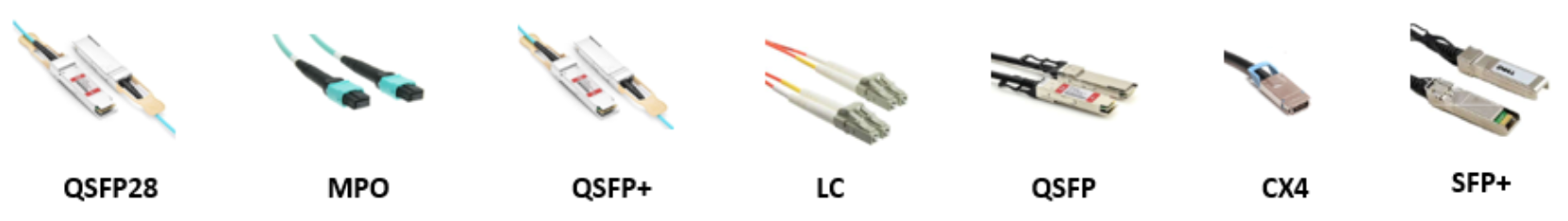
The various cable types, form factors, and supported lengths available for PowerScale nodes include:
Cable form Factor
Medium
Speed (Gb/s)
Max length
QSFP28
Optical
100Gb
30M
MPO
Optical
100/40Gb
150M
QSFP28
Copper
100Gb
5M
QSFP+
Optical
40Gb
10M
LC
Optical
25/10Gb
150M
QSFP+
Copper
40Gb
5M
SFP28
Copper
25Gb
5M
SFP+
Copper
10Gb
7M
CX4
Copper
IB QDR/DDR
10M
The connector types for the cables above can be identified as follows:
As for the nodes themselves, the following rear views indicate the locations of the various network interfaces:
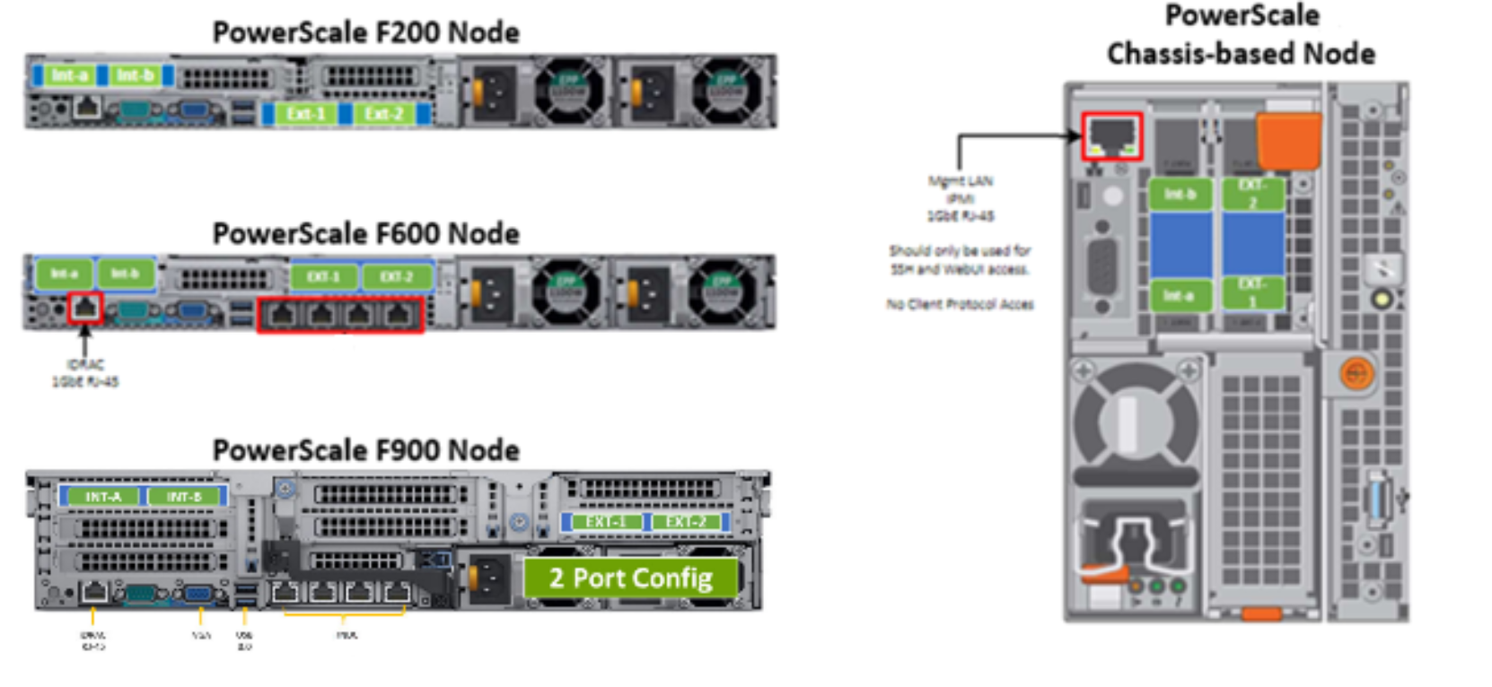
Note that Int-a and int-b indicate the primary and secondary back-end networks, whereas Ext-1 and Ext-2 are the front-end client networks interfaces.
Damage to the InfiniBand or Ethernet cables (copper or optical fibre) can negatively affect cluster performance. Never bend cables beyond the recommended bend radius, which is typically 10–12 times the diameter of the cable. For example, if a cable is 1.6 inches, round up to 2 inches and multiply by 10 for an acceptable bend radius. Cables differ, so follow the explicit recommendations of the cable manufacturer.
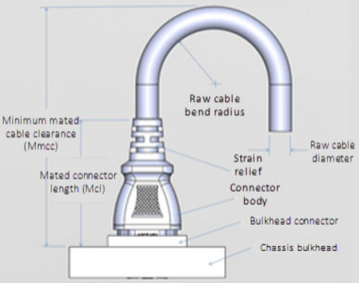
The most important design attribute for bend radius consideration is the minimum mated cable clearance (Mmcc). Mmcc is the distance from the bulkhead of the chassis through the mated connectors/strain relief including the depth of the associated 90 degree bend. Multimode fiber has many modes of light (fiber optic) traveling through the core. As each of these modes moves closer to the edge of the core, light and the signal are more likely to be reduced, especially if the cable is bent. In a traditional multimode cable, as the bend radius is decreased, the amount of light that leaks out of the core increases, and the signal decreases. Best practices for data cabling include:
- Keep cables away from sharp edges or metal corners.
- Avoid bundling network cables with power cables. If network and power cables are not bundled separately, electromagnetic interference (EMI) can affect the data stream.
- When bundling cables, do not pinch or constrict the cables.
- Avoid using zip ties to bundle cables. Instead, use Velcro hook-and-loop ties that do not have hard edges, and can be removed without cutting. Fastening cables with Velcro ties also reduces the impact of gravity on the bend radius.
Note that the effects of gravity can also decrease the bend radius and result in degradation of signal power and quality.
Cables, particularly when bundled, can also obstruct the movement of conditioned air around the cluster, and cables should be secured away from fans, and so on. Flooring seals and grommets can be useful to keep conditioned air from escaping through cable holes. Also ensure that smaller Ethernet switches are drawing cool air from the front of the rack, not from inside the cabinet. This can be achieved either with switch placement or by using rack shelving.
The following table shows the various front and back-end network speeds and connector form factors across the PowerScale storage node portfolio:
Speed (Gb/s)
Form factor
Front-end/
Back-endSupported nodes
100/40
QSFP28
Back-end
F910, F900, F710, F600, F210, H700, H7000, A300, A3000, P100, B100
40
QDRQSFP+
Back-end
F800, F810, H600, H5600, H500, H400, A200, A2000
25/10
SFP28
Back-end
F910, F900, F600, F210, F200, H700, H7000, A300, A3000, P100, B100
10
QDRQSFP+
Back-end
H400, A200, A2000
100/40
QSFP28
Front-end
F910, F900, F710, F600, F210. H700, H7000, A300, A3000, P100, B100
40
QDRQSFP+
Front-end
F800, F810, H600, H5600, H500, H400, A200, A2000
25/10
SFP28
Front-end
F910, F900, F710, F600, F210, F200, H700, H7000, A300, A3000, P100, B100
25/10
SFP+
Front-end
F800, F810, H600, H5600, H500, H400, A200, A2000
10
QDRSFP+
Front-end
F800, F810, H600, H5600, H500, H400, A200, A2000
With copper (CX4) InfiniBand cables the maximum cable length is limited to 10 meters. After factoring in for dressing the cables to maintain some level of organization and proximity within the racks and cable trays, all the racks containing a cluster’s nodes need to be in close physical proximity to each other –either in the same rack row or close by in an adjacent row.
Support for multimode fiber (SC) for InfiniBand and for Ethernet extends the cable length limitation to 150 meters. This allows nodes to be housed on separate floors or on the far side of a floor in a data center if necessary. While solving the floor space problem, this has the potential to introduce new administrative and management issues.
With large clusters, especially when the nodes may not be racked in a contiguous manner, having all the nodes and switches connected to serial console concentrators and remote power controllers is highly advised.
OneFS 9.0 and later include IPMI (Intelligent Platform Management Interface) support for PowerScale platforms. This functionality allows out-of-band console access and remote node power control through a dedicated Ethernet management port, and is configured and managed using the ‘isi ipmi’ CLI command set.
However, to perform any physical administration or break/fix activity on nodes you must know where the equipment is located and have administrative resources available to access and service all locations.
As such, the following best practices are highly recommended:
- Develop and update thorough physical architectural documentation.
- Implement an intuitive cable coloring standard.
- Be fastidious and consistent about cable labeling.
- Use the appropriate length of cable for the run and create a neat 12” loop of any excess cable, secured with Velcro.
- Observe appropriate cable bend ratios, particularly with fiber cables.
- Dress cables and maintain a disciplined cable management ethos.
- Keep a detailed cluster hardware maintenance log.
- Where appropriate, maintain a ‘mailbox’ space for cable management.
Disciplined cable management and labeling for ease of identification is particularly important in larger PowerScale chassis-based clusters, where the density of cabling is high, with each chassis requiring up to twenty-eight cables.
Medium
Cable quantity per chassis
Back end network
Ethernet or Infiniband
8
Front end network
Ethernet
8
Management Interface
1Gb Ethernet
4
Serial Console
DB9 RS 232
4
Power cord
110V or 220V AC power
4
Total
28
The recommendation for cabling a PowerScale chassis, such as the H700 or A3000, is as follows:
- Split cabling in the middle of the chassis, between nodes 2 and 3.
- Route Ethernet and InfiniBand cables towards the lower side of the chassis.
- Connect power cables for nodes 1 and 3 to PDU A and power cables for nodes 2 and 4 to PDU B.
- Bundle network cables with the AC power cables for ease of management.
- Leave enough cable slack for servicing each individual node’s FRUs.
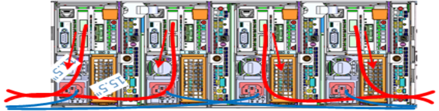
Figure 5. Gen6 chassis rear illustrating split cabling
The stand-alone PowerScale F-series all flash nodes, in particular the 1RU F710, F600, F210, and F200 nodes, also have a similar density of cabling per rack unit:
Cabling component
Medium
Cable quantity per F-series node
Back end network
10 or 40 Gb Ethernet or QDR Infiniband
2
Front end network
10 or 40Gb Ethernet
2
Management Interface
1Gb Ethernet
1
Serial Console
DB9 RS 232
1
Power cord
110V or 220V AC power
2
Total
8
Consistent and meticulous cable labeling and management is particularly important in large clusters.
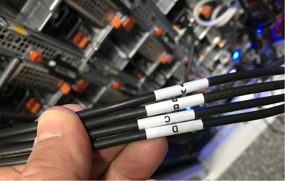
Figure 6. Network cable labeling example
While there is no requirement that node 1 aligns with port 1 on each of the backend switches, it can certainly make cluster and switch management and troubleshooting considerably simpler. Even if exact port alignment is not possible, with large clusters, ensure that the cables are clearly labeled and connected to similar port regions on the backend switches.