
Redundant power subsystem
Redundant power subsystem
-
A modular power subsystem features a redundant architecture that facilitates field replacement of any of its components without any interruption in processing.
The power subsystem has two power zones for redundancy. Each power zone connects to a separate dedicated or isolated AC power line. If AC power fails on one zone, the power subsystem continues to operate through the other power zone. If any single power supply module fails, the remaining power supplies continue to share the load. PowerMaxOS senses the fault and reports it as an environmental error.
Each director is configured with a management module that provides low-level, system-wide communications and environmental control for running application software, monitoring, and diagnosing the system. The management modules are responsible for monitoring and reporting any environmental issues, such as power, cooling, or connectivity problems.
Environmental information is carried through two redundant Ethernet switches. Each management module connects to one switch, except for the MMCS modules in Engine 1 which connect to both Ethernet switches. Management module A connects to Ethernet switch A, and management module B connects to Ethernet switch B. Each management module also monitors one of the system standby power supplies (SPS) through an RS232 connection. Standard PowerMax 8000 racks have LED bars that are connected to the management modules and are used for system or bay identification during service activities.
Figure 15 illustrates management module connectivity.
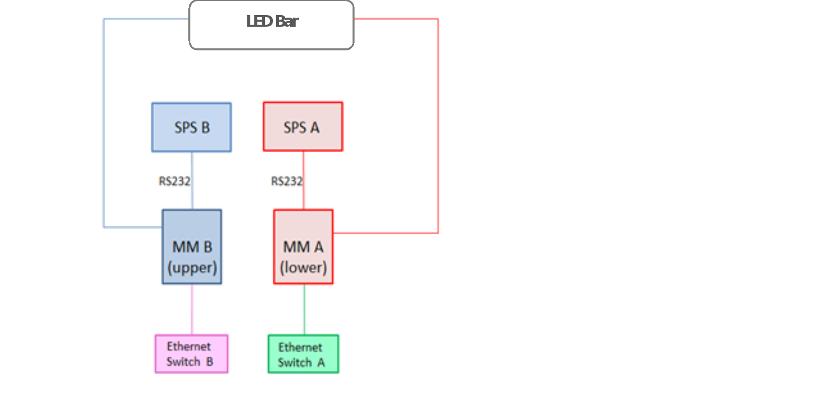
Figure 15. Management module connectivity
The internal Ethernet connectivity network monitors and logs environmental events across all critical components and reports any operational problems. Critical components include director boards, global memory, power supplies, power line input modules, fans, and various power switches. The network’s environmental control capability can monitor each component’s local voltages, ensuring optimum power delivery. Temperature of director boards and memory are also continuously monitored. Failing components can be detected and replaced before a failure occurs.
The AC power main is checked for the following:
- AC failures
- Power loss to a single power zone
- DC failures
- Current sharing between DC supplies
- DC output voltage
- Specific notification of overvoltage condition
- Current from each DC supply
- Voltage drops across major connectors
Figure 16 illustrates the internal Ethernet connectivity.
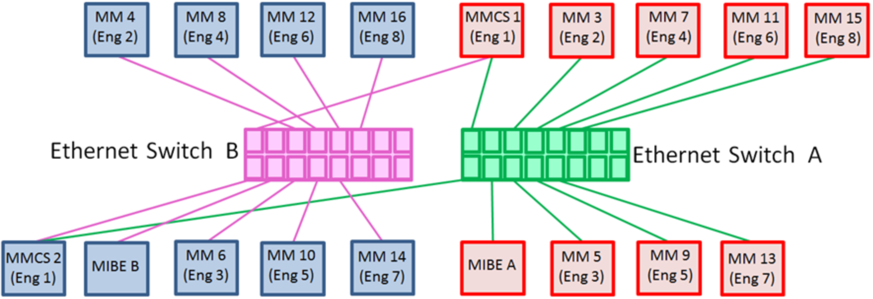
Figure 16. Internal Ethernet connectivity