
Metro-based NDM overview
Metro-based NDM overview
-
All migrations to Dell PowerMax arrays use Metro-based NDM built upon SRDF/Metro active/active technology. For more information about SRDF/Metro, see the SRDF/Metro Overview and Best Practices document.
Benefits of using Metro-based NDM include the following:
- Allows the complete migration from a VMAX3 or VMAX All Flash arrays to VMAX All Flash or PowerMax arrays without the need for downtime
- Leverages Metro technology to reduce the required commands users need to issue by removing the need to cut over
- Is managed by familiar and simple user interfaces: Solutions Enabler and Unisphere for VMAX
- Allows migrations to be canceled easily and failed back to the source array for any reason prior to commit
- Allows users to precopy all or a large portion of data before bringing the host live to the new array. This reduces the impact to the application during the migration period.
Previous versions of NDM provided with Solutions Enabler 8.3, Unisphere 8.4, and HYPERMAX OS 5977.1125 releases allowed data to be migrated from a VMAX (5876) to a VMAX3 (5977) array without application downtime.
With the release of Solutions Enabler 9.0 and HYPERMAX OS Q2 2018, the NDM feature was enhanced to help automate the process of moving applications from a VMAX3 (5977) or VMAX All Flash (5977) array to another VMAX All Flash (5978) or PowerMax (5978) array.
With the later release of Solutions Enabler 9.1 and higher, full interfamily migrations are possible (5977 to 5977, 5978 to 5978 or 6079, or 6079 to 6079).
The source hardware is not a limiting factor. Metro-based NDM is supported from arrays running 5977 or 5978 to 5977,5978 or 6079 code, regardless of the underlying technology.
With SRDF/Metro, the session goes active/active only after all SCSI information and application data is synchronized from R1-R2 using SRDF adaptive copy technology. The time to be fully active/active largely depends on the time it takes for the data transfer to finish.
To improve the user experience with NDM, the software is enhanced such that the SRDF/Metro session goes active/active instantly on NDM create. This instant active mode of operation only applies to underlying Metro technology for NDM and does not apply to regular SRDF/Metro for running active/active applications. This makes both sides of the SRDF/Metro active and read/write to the host within the duration of the create command.
Metro-based NDM modes of operation
- Metro-based NDM: This is the NDM mode where the synchronization starts right after the create completes, and the create operation creates an NDM session using SRDF/Metro internally.
- Metro-based NDM with precopy: This mode of operation offers a choice to start the NDM session using adaptive copy (SRDF/ADP) which helps synchronize most of the data before moving into an active/active state. When copy is near complete, user will issue a Ready Target to move to active/active mode synchronizing any remaining tracks. In essence, precopy allows end users to copy application data from the source array to the target in a reducing any performance impact for the initial data copy process.
Supported distance between source and target
NDM is supported across SRDF synchronous distances. However, because of the requirement that the host see both the source and target storage, migrations are typically performed between arrays within a data center.
Metro-based flows
The following steps and diagram describe the process flow for Metro-based NDM:
- Solutions Enabler creates an active/active SRDF group with NDM attribute.
- Solutions Enabler activates the group.
- SCSI information, device personality, and attributes are transferred to the target devices.
- Masking view to the source (R2) array created.
- Migration starts from R1 to R2 (source to target).
- User rescans host for extra paths to target array.
- Data synchronization completed.
- Commit issued and migration completed.
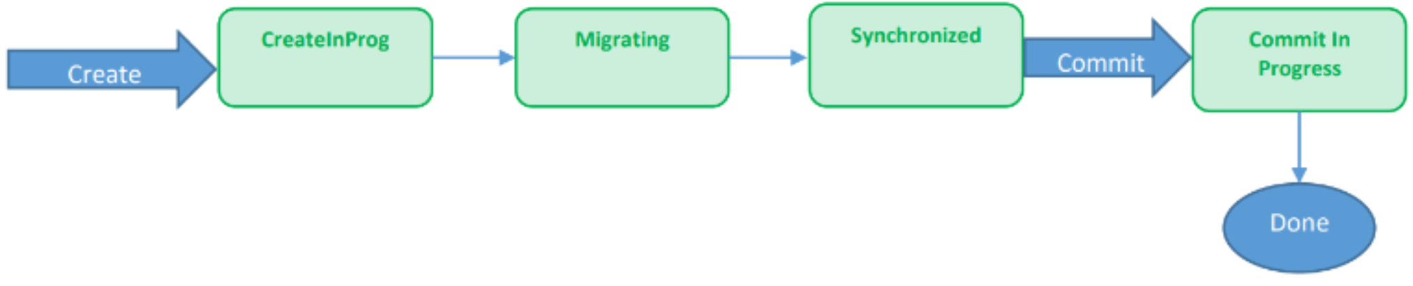
Figure 1. Process flow for Metro-based NDM
The following steps and diagram describe the component flow for Metro-NDM with precopy:
- Solutions Enabler creates an active/active group with NDM attribute and precopy set. The SRDF group is set to adaptive copy mode.
- Pre-copy data sync (R1-R2)
- Solutions Enabler sets READYTGT which will activate RDF group with Metro-IA.
- SCSI information, device personality, and attributes are transferred to the target devices.
- Masking view to the source array created.
- User rescans host for extra paths to the target array.
- Data synchronization completed.
- Commit issued and migration completed.

Figure 2. Component flow for Metro-based NDM with precopy
Metro-based NDM operations
- Create: This creates a Metro-based NDM session. It creates SRDF/Metro with NDM source and target attributes and puts the NDM pair in active/active mode (clear DEV-INACT on R2). This also starts data synchronization and SCSI info synchronization and moves into a migrating state. Once the data has been synchronized and the host paths to the target array have been discovered by means of a host rescan, the NDM session reaches a synchronized state. A create results in RDF mirror invalids on R1 and local mirror invalids on R2.
- Create with precopy: This creates an SRDF/Metro session with NDM attributes and puts the SRDF/Metro pair into adaptive copy disk mode. It starts data synchronization from R1 to R2. Bias is enabled on the Metro-based NDM source. This creates an SRDF/Metro session with NDM attributes and puts the SRDF/Metro pair into adaptive copy disk mode. It starts syncing data from R1 to R2. Bias is on the Metro-based NDM source.
- ReadyTGT: This continues to synchronize the remaining invalid tracks from source to target and synchronizes SCSI Information for migrating devices. It puts the NDM pair in active/active mode (clear DEV-INACT on R2) without waiting for synchronization to finish.
- Cancel: This suspends the SRDF/Metro NDM session. The R2 device moves into a DEV-INACT state, and all I/O is redirected to R1.
- Sync-stop: Once in synchronized state, the user might need to test the application performance before committing. The sync-stop command would make the NDM SRC DEV-INACT, all I/O would go through Metro-NDM target R2, and the Metro-NDM session moves into a CutoverNoSync state. This operation results in moving the bias to the Metro-NDM target.
- Sync-start: This moves the Metro-NDM session from CutoverNoSync to CutoverSyncing and finally to synchronized. This command should be used once the user has finished verifying the application against the NDM target after the sync-stop command and the user is ready to either commit or cancel the NDM session. The bias remains on the Metro-NDM target commit.
Manipulation of device IDs and host paths
Two of the underlying processes that ensure that NDM is non-disruptive is the ability to always maintain device visibility by spoofing and swapping devices IDs between source and target devices.
NDM can migrate data and cut over to the target array non-disruptively by both swapping device IDs between the source and target devices and manipulating the paths from the host to both arrays. The device ID contains the device’s unique WWN and other information about it, such as a device identifier that the user has assigned to a device through Solutions Enabler or Unisphere. All this information is copied to the target devices.
NDM performs the data migration and device ID swap without the host being aware. The path management changes appear as either the addition of paths or the removal of paths to the existing source device. To the host and application, there is no change in the device that it is accessing and access to the device is maintained throughout the entire migration process.
For an example of this in action see section Examine paths and device post commit.
Effects on devices and existing replication sessions
Devices included in a migration session on the source array can remain in existing replication sessions throughout the migration. NDM evaluates the state of any current replication sessions before proceeding with the migration and makes sure that they are in the proper state to allow the migration to succeed. By maintaining existing replication, NDM ensures there is no Recovery Point Objective (RPO) impact during the period of the migration.
Though existing replication sessions can be left in place during the migration, replication relationships are not migrated to the target array. These replication resources need to be created on the target array, if required, at the appropriate point in the migration.
For example, SRDF replication can be configured between the target array and its remote array while in the CutoverSyncing state or after the CutoverSync state is reached. The new DR RDF pairs can then be allowed to synchronize before the commit so that DR is maintained throughout the migration. SRDF can also be set up in the CutoverNoSync state, which is reached when the sync command is used to stop replication. For local Snap/VX sessions running against the source volumes, existing sessions on the source array can continue as normal during the migration and new sessions can also be created while the new SRDF to the DR site is configured.
Storage on the source and target arrays that is involved in the migration of an application should never be altered, and the migration resources should not be managed, outside of the NDM commands. If any changes in the migration session are detected when a migration operation is performed, the operation is blocked until the changes that were made are undone, allowing the migration operation to proceed as expected.
The following are examples of manual changes made to the NDM session that will cause the session to stop or fail:
- Storage group manipulation, or adding or removing devices
- Masking view manipulation such as changing the name, or adding or removing elements
Configuration requirements and prerequisites
Most of the steps for configuring and unconfiguring NDM are done automatically using the environment setup and remove commands. Prior to running the setup, the following steps are required:
- SRDF ports must be configured across at least two directors.
- The source and target arrays must have SRDF directors and ports configured.
- The SRDF ports between the source and target arrays in a Fibre Channel environment must be zoned to each other.
- A Solutions Enabler or Unisphere management host that sees at least one of the arrays must be available.
- The host with the application being migrated must be zoned to the VMAX3 or VMAX All Flash array.
Note: SRDF ports do not need to be dedicated to NDM operations. Ports involved in ongoing SRDF disaster recovery operations may be shared with NDM sessions, but analysis should be performed prior to setting up NDM to make certain there is adequate bandwidth to handle both DR and migration traffic.
Restrictions
NDM SRDF restrictions
- Potential source devices cannot be R2 devices.
- Arrays must be within metro distances of each other.
- The source devices cannot be part of a concurrent RDF relationship.
- The source devices must not be enabled for RDF consistency.
- The source devices may not be part of an SRDF/Star configuration.
- Metro with SRDF Disaster Recovery configured on both sites is not supported
- Storage Groups protected by SRDF Metro Smart DR are not supported
Environment restrictions
A minimum of two SRDF links (FC or GigE) are required to support an NDM session. These ports must be spread across at least two directors.
Open replicator restrictions
- The migration source device may not be the control device in an Open Replicator pull operation.
- Open Replicator must not be replicating data from a remote device to a control device, such as during an in-progress restore.
TimeFinder restrictions
- The source or target devices may not be the target of a TimeFinder copy session.
- SRDF must not be replicating data from a local replication operation, such as during an in-progress TimeFinder restore.
RecoverPoint restrictions
The migration source or target devices cannot be tagged for RecoverPoint use.
Boot-from-SAN support
Cutover NDM supports hosts that boot directly from the VMAX array. The host boot BIOS must be updated to point to the target volume so that when the host is rebooted later it will find the volume containing the operating system. For details on boot drive configuration, refer to the vendor specific HBA management guide or BIOS guides.
REST API support
All features and functionality for Data Mobility with Non-Disruptive Migration are fully supported through the REST API. See Dell PowerMax API documentation for further information.
Recognizing the NDM SRDF group
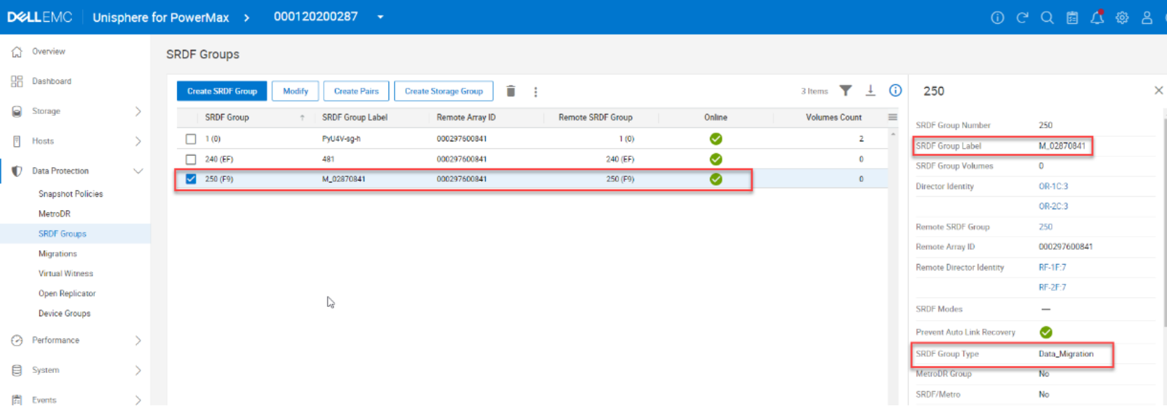
The RDF group created for NDM between two arrays can be identified by its label. The label follows the format of M_XXXXYYYY. XXXX is the last four digits of the lower numbered storage array and YYYY is the last four digits of the higher numbered array. This group is used for all NDM migrations between the two arrays. This group is automatically created as part of the environment setup. Figure 3 The following figure shows the group as views through Data Protection > SRDF Groups view in Unipshere for PowerMax.Figure 3. Viewing SRDF groups In Unisphere for PowerMax
Setting up multiple NDM environments
Multiple-environment setup operations can be performed for a single source array, provided that a different target array is specified for each migration environment. All NDM RDF groups on a source or target array can be in use simultaneously, for concurrent migrations to or from an array.
For example, a single PowerMax, VMAX All Flash, or VMAX3 target array can have multiple NDM RDF groups, each connected to one of four different source arrays. This means that the target array can be the target of migrations from each of those four arrays in a consolidation use case.
Likewise, a single source array can have multiple NDM RDF groups, each connected to one of four different targets. This means that storage groups on the source array can be migrated to any of those four PowerMax arrays.
When migrations are completed, the environment can be removed for each array pair. The environment remove operation removes the NDM RDF group between the two arrays, provided that no devices on either array have an RDF mirror in the NDM RDF group.
Masking groups and views with NDM
When NDM sessions are created, NDM configures the following items on the target array with the same names as those on the source array:
- Storage groups (SGs)
- Initiator groups (IGs)
- Port groups (PGs) – can also be created in advance by the user.
- Masking views (MVs)
Both initiator groups and port groups can exist in multiple masking views, so these groups are reused when applicable.
A host also may be attached to multiple source arrays. For example, if a storage group spans two source arrays, when the storage is migrated, the target array contains two sets of SGs, IGs, PGs, and MVs, one for each source array.
When the first SG on the first array is migrated to the target array, the following occurs:
- An SG is created on the target with the same name that contains the migration target devices.
- An IG is created on the target with the same name that contains the host initiators.
- A PG is created on the target based on which ports the host HBAs are logged into, or user selects an existing one using the migration wizard.
When a second SG on the second source array is migrated to the target array, the following rules apply:
- The SG name must be different.
- If necessary, the SG can be renamed before it is migrated.
- The IG must have the same name because an initiator can only exist in one IG.
- If the PG on the second array has the same name as the PG on the first array, the PG built by NDM during the first migration can be reused. If it has a different name, a new PG will be created with the same ports used in the PG created during the first migration.
Alternatively, you can manually create the PG on the target in advance. Then, select this as the target PG for the NDM session or create it as part of the NDM create process. This option is new for Solutions Enabler 9.1.
Rules for masking groups and views
All migrations are performed against an SG, which is the data container that is migrated with NDM. The following rules apply:
- Only SGs contained in masking views can be migrated. If the device is mapped to a port that it is not masked to for this SG, the create operation is not permitted.
- Multiple masking views on the SG using the same IG are not allowed unless PGs on the target array already exist for each view and the ports in the PGs are selected to avoid duplicate host paths.
- If the SG is a parent, its child SGs are also migrated.
- Devices in the SG which are Gatekeepers (10MB less) are not migrated to the target array. Devices must not be masked to FCoE ports.
- Devices must not be masked to iSCSI ports.
- Devices must not be mapped to ports where the ACLX is not enabled.
- If a storage resource pool (SRP) on the target array is specified for the migration, that SRP must already exist on the target array. The names of the SGs (parent and children) that are being migrated must not exist on the target array.
- The names of the masking views that are being migrated must not exist on the target array.
- The names of the initiator groups that are being migrated may exist on the target array, the IG layout may differ on the target array to that on the source.
- The names of the port groups that are being migrated may exist on the target array, provided that the groups on the target array have the initiators logged in into at least one port in the port group.
NDM general considerations and limitations
- Migrating hosts must have access and be zoned to both the source and target array
- Migrating hosts must use Fibre Channel connectivity
Session limits
- 50 SGs can be migrated concurrently. Child SGs do not count towards this limit.
- Each SG can contain up to 4096 devices.
Hardware and software requirements
For hardware and software requirements, refer to the PowerMax/VMAX All Flash/VMAX3 Features Simple Support Matrix.