Metro-based NDM guide plan and environment overview
Metro-based NDM guide plan and environment overview
-
The following guide walks through both options for Metro-based NDM using Unsiphere for PowerMax, equivalent Solutions Enabler CLI commands are also listed:
- Metro-based NDM:
- Metro-based NDM with precopy:
Note: REST API can also be used to setup and manage the migration process for non-disruptive migration.
The duration of this walkthrough will follow the migration of a storage group named “Migrate Me” from array serial 000297600841 to array serial 000120200287.
Prior to the start of a planned migration, verify the following:
- Ensure both source and target array are RDF capable (the RF emulation has been added to both arrays).
- Ensure both arrays RDF ports are zoned to each other. There is a minimum of two connections required.
- Check for the correct zoning from the target array to the application host.
Pre-Requisites before starting a Migration
Before any migration can be created the environment must be configured, the steps to configure NDM environment regardless of underlying technology is the same. See section Creating an NDM Environment with Unisphere for PowerMaxError! Reference source not found..
Create migration session
- From the Storage tab click Storage Groups.
- Locate the SG to be migrated. Select the checkbox and click the More Actions (three dot icon) to the right of Set Host I/O Limits. From the drop-down menu select Migrate.
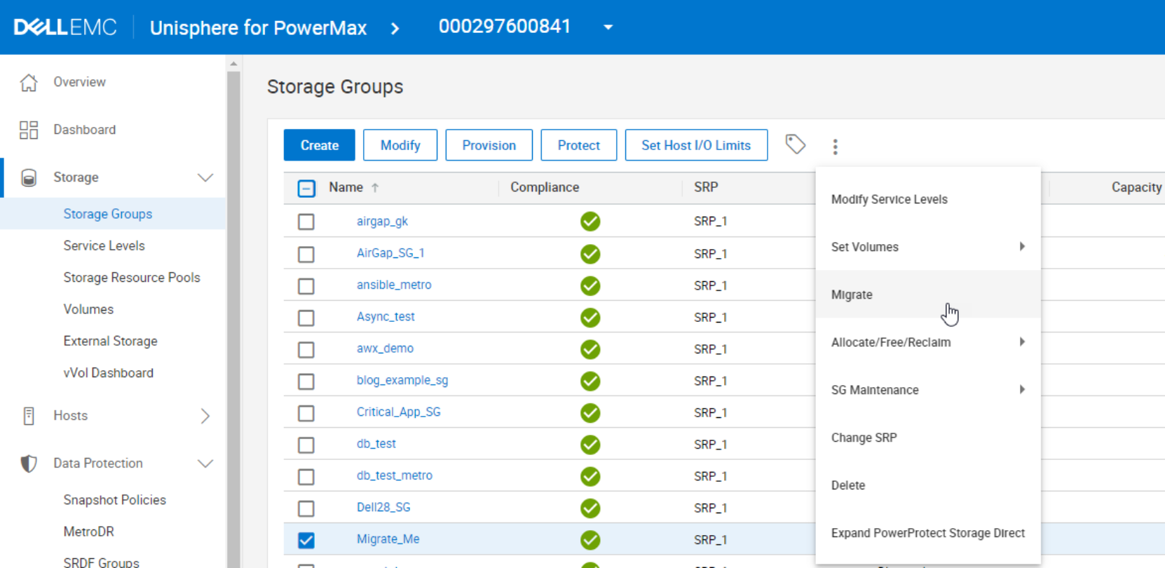
Figure 19. Launching Migration Wizard – Unisphere for PowerMax Storage Groups View
In the Create Migration Wizard, select the Target array (only arrays with valid environments setup appear on this drop-down menu).
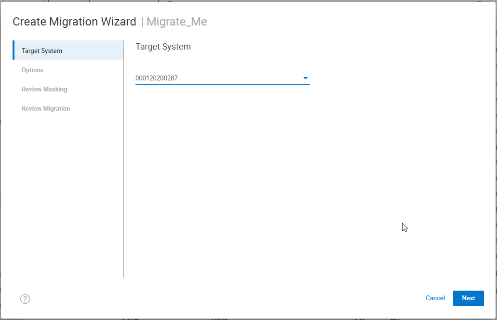
Figure 20. Select Target System - Creation Migration Wizard
On the next screen click Create Data Migration. This provides the option of Enable Data Reduction, Precopy, and Offline. The scenario that this part of the example covers does not use Precopy or Offline, so these options remain unchecked.

Figure 21. Migration Options – Unipshere Migration Wizard
The Review Masking section of the wizard summarizes the planned NDM session to be created. It breaks down the planned masking view elements and the NDM parameters.
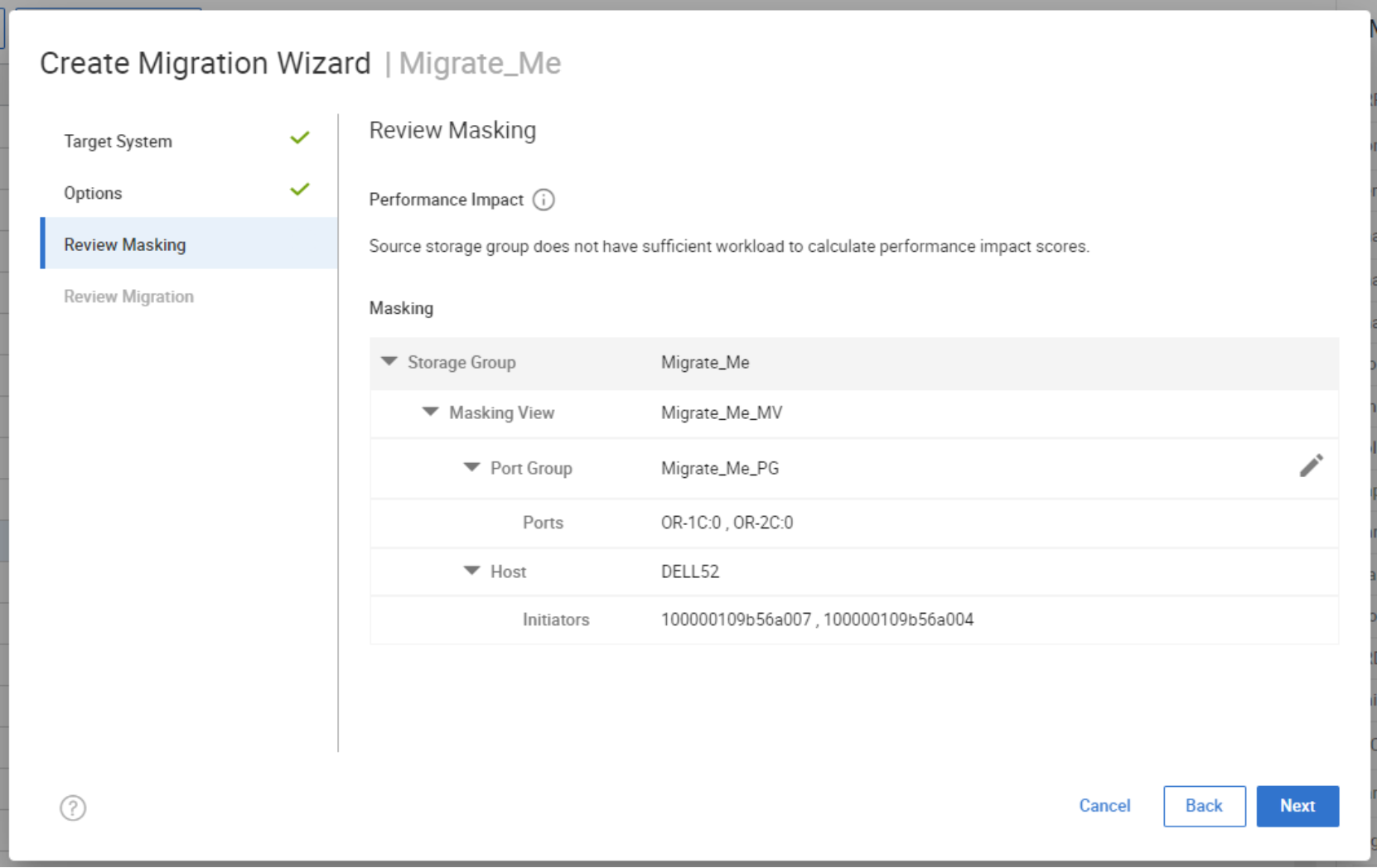
Figure 22. Review Masking – Unisphere Migration Wizard
The Performance Impact score requires performance data to be collected on the host.
This runs a check for resources on the target array to ensure the addition of the new SG does not cause the target array to exceed any performance metrics on both FE and BE. It also produces a spread sheet to help plan the zoning required for the host from the target array.
The last section on the wizard allows the user to review the migration with the options selected, at this point the user also has the ability to schedule the migration to start at a recommended time based on the system workload to minimize any performance impact, when the user selects this option the dialog will change to add to job list which will schedule the migration to start at the suggested time or one configured by the user, perhaps during approved change windows.
For the example, select Run Now to continue.
Figure 23.

Review Migration – Unisphere Migration WizardCreating the NDM session will also perform an environment validate as part of the setup to ensure it will complete successfully. As outlined in the create command output, the Create:
- Creates a Storage Group on the Target array (name must not already exist in the target array) with the same name as the Source SG.
- Creates duplicate devices on the target array to match those on the Storage Group
- Creates an initiator group using Initiators with entries in the login history table
- Creates a Port group (if one does not already exist or has not been selected by the user, see the relevant masking enhancements section)
- Invalidates the tracks on the RDF mirror to prepare for the copy
- Starts the copy process.
- Creates a masking view to the host from the target array.
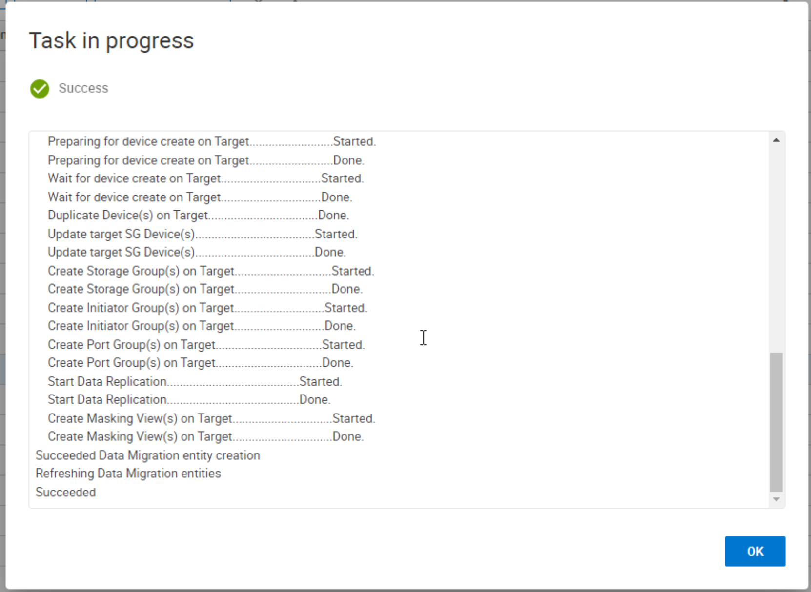
Figure 24. Create Migration Task Summary
Examine the created migration session
Selecting the Data Protection tab on the left task bar and selecting Migrations in the drop-down menu, the storage groups currently involved in an NDM session are highlighted along with the current State and details on the source and target arrays. Since data transfer begins immediately following a Create operation there is no need for the Pass-Through NDM Cutover operation. Once the data is synchronizing the systems administrator runs a rescan to allow the target paths to become active to the multipathing software. At this point, both source and target arrays are involved in an active/active relationship with all I/O serviced locally.

Figure 25. Migration Session in Synchronized State
Double-clicking the NDM session takes you into the Migration Details view. The figure below shows the devices involved in the session from source and target arrays. Under the target tab we can see devices 40F - 413 have been created on the target side by the NDM create. The State also shows a live status of each of the devices involved. A device without a green tick should be investigated for potential problems before continuing.
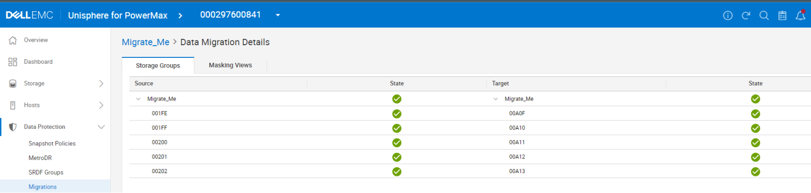
Figure 26. Migrating Devices and Target Devices viewed from Migration Session
Selecting the Masking Views tab displays the pane outlining the masking and masking elements involved on both sides of the NDM session. This screen can be useful for troubleshooting any issues with the migration such as an unplanned or unauthorized manipulation of any of the NDM elements that hinder progress to the commit stage. In such cases the State does not contain a green tick, rather a red warning.
View paths to new devices and SRDF pairs
The following screenshots show before and after views of device pathing from the multipathing software on the migrating server. After a SCSI rescan shows the host now as extra paths online to the target array for the migrating devices (in this case two extra paths). The number of extra paths is dependent on the zoning setup and number of ports in target port group.
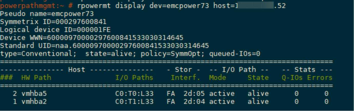
Figure 27. Multipathing Before Rescan
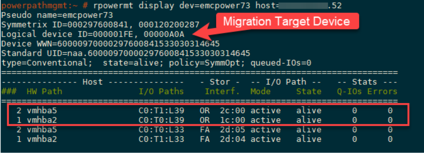
Figure 28. Multipath Details while devices are migrating.
Multipathing output from PowerPath shown in Figure 28 displays the source and target array serial numbers and the device numbers on both arrays. The WWNs on the LUNs to appear as a single device with just extra paths. Prior to version 6.2 PowerPath was not aware of the NDM process so the dual SIDs and devices IDs were not visible.
Once the Create operation and the scan have both completed, the migration is in an active/active functional state with I/Os being distributed to both source and target paths. Bias is set on the Source side which differs from Pass-Through NDM where the source side was the R2 in a standard R1- R2 synchronous relationship. The state in Unisphere is displayed as ActiveBias as we do not have a witness attached to this metro relationship. However, we are truly active/active from a device accessibility perspective. The panel on the right indicates which arrays can receive I/O from hosts.

Figure 29. Device SRDF status viewed from Unisphere
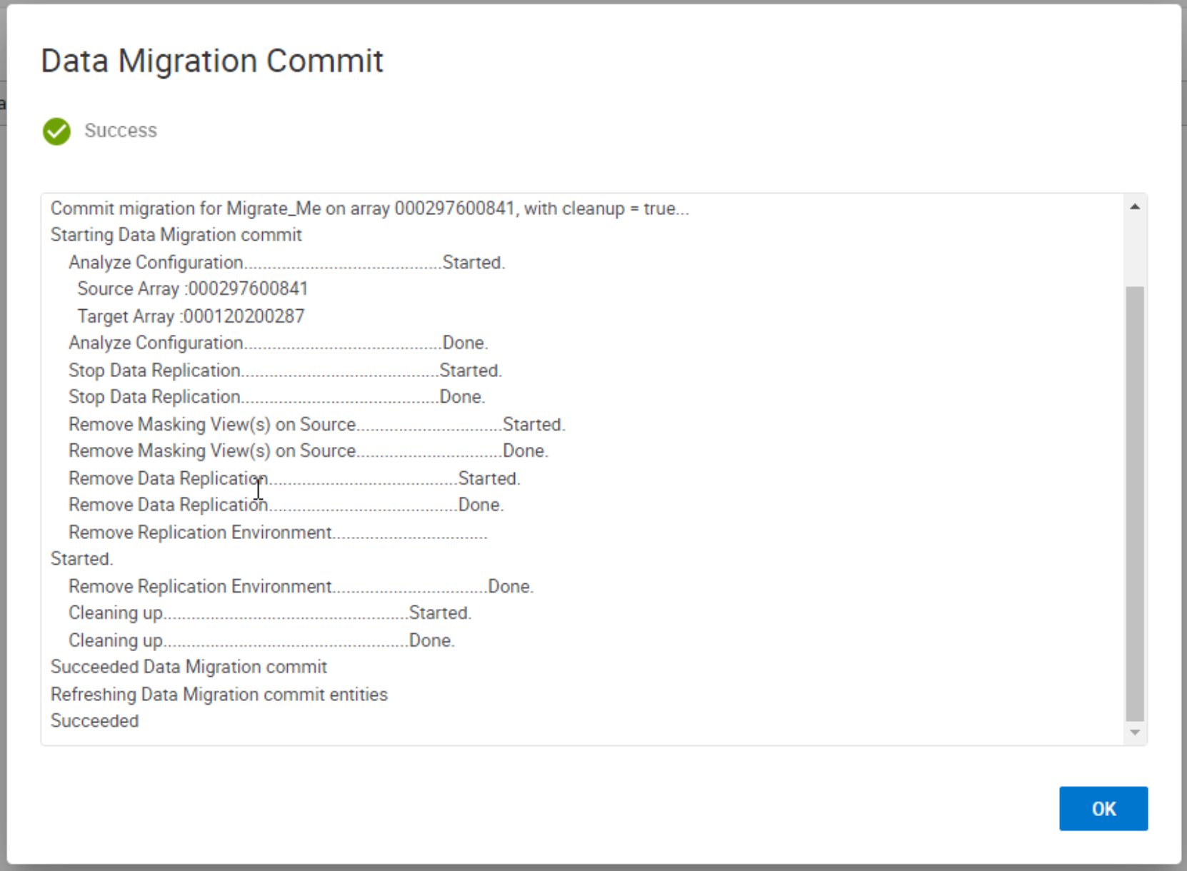
Commit a migration
When the data commit operation is completed and the devices are synchronized, the migration can be committed. The Commit operation completes the migration by removing the migrated application resources from the source array and releases system resources used for the migration. Once the commit is completed the replication relationship between the source and target devices are removed, the masking view on the source removed and the source devices take the native (internal) WWN of the target LUN as its effective (external) WWN.
The target has an external WWN of the source and the source having an external WWN of the target. Both devices retain their native (internal) WWNs but these are not presented to the host.
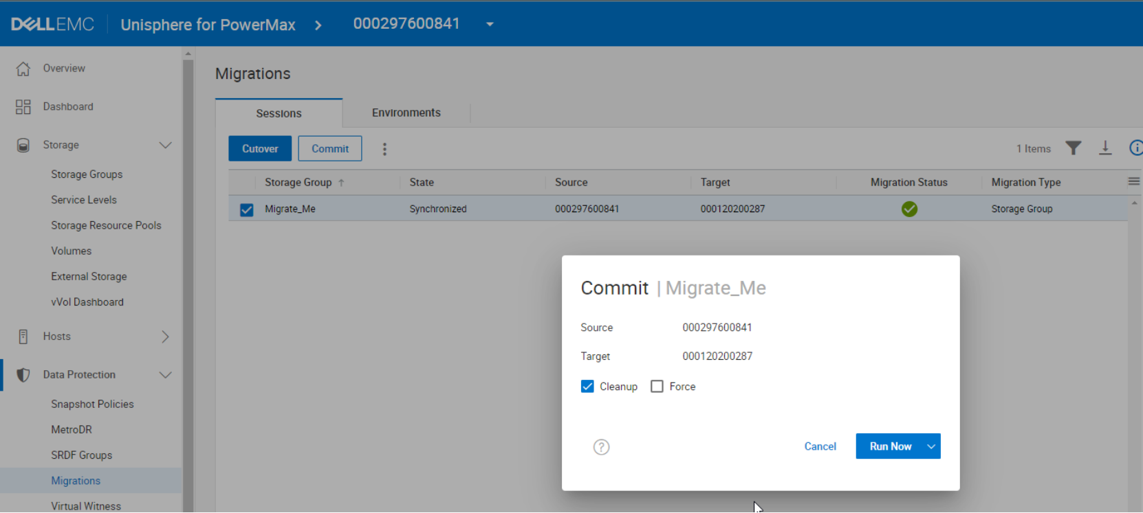
Figure 30. Commit Migration Session
Figure 31. Commit Summary
Examine paths and device post commit
Post Commit and with the removal of the source masking view and before the host rescan the original Source paths are in a dead state. (This varies depending on your MP software) The paths on the new array stay active.
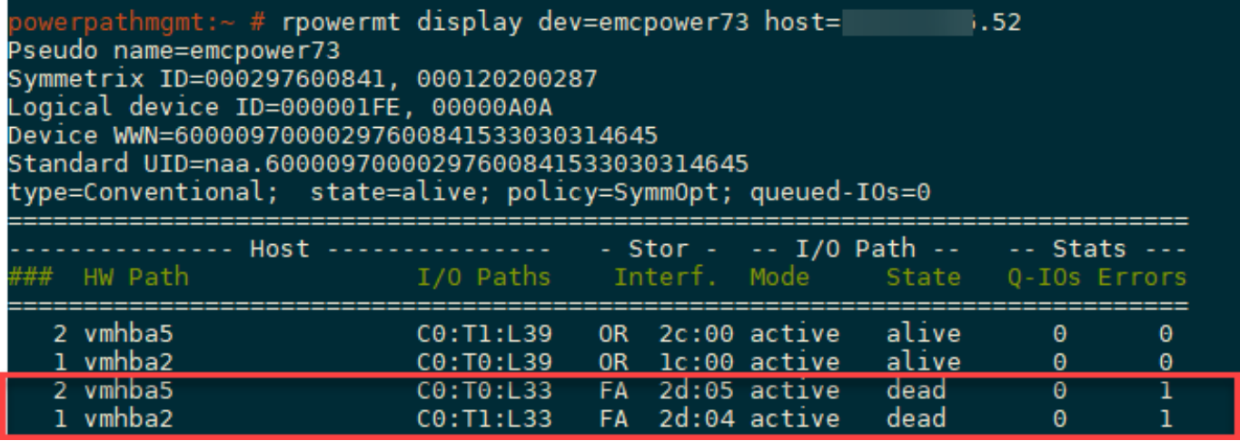
Figure 32. Paths to Migrated Device post commit
Once the host Rescan has been completed, the dead paths are now removed and the SID that of the target array is no longer displayed in the rpowermt display output. The WWN inherited from the source array remains unchanged.

Figure 33. Pathing Details after commit and host rescan of SCSI devices
Viewing the source and target devices after the Commit operation clearly shows the WWN manipulation that has occurred. The Source device shown in the figure below now has the target’s native WWN as its External Identity WWN and the target device Figure 35has retained the source native WWN as its External Identity WWN.
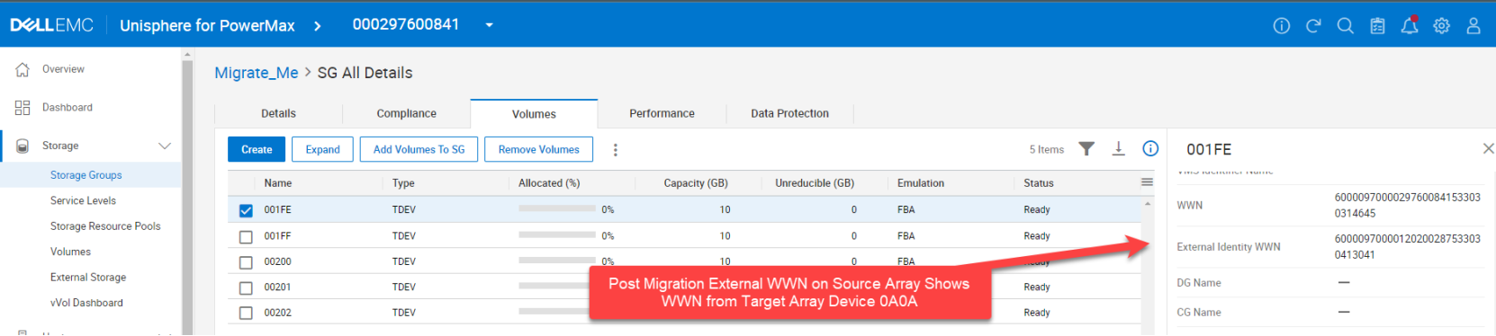
Figure 34. Source Device Details Post Migration
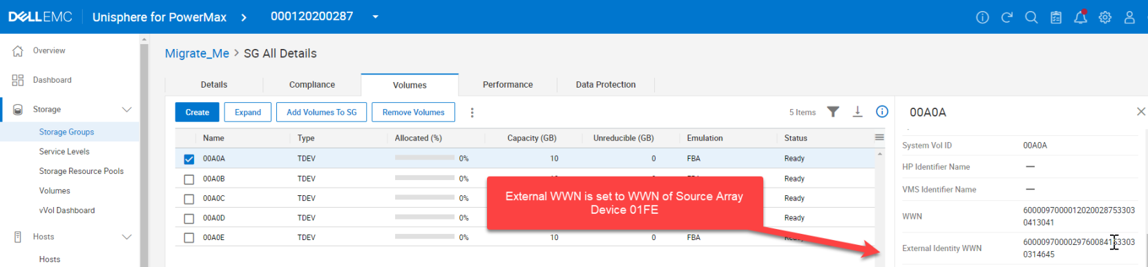
Figure 35. Target Device Details Post Migration
Note: At this point, the data migration is completed, and the migration environment can be removed if no longer required.