
Add DR to target SG before synchronization
Add DR to target SG before synchronization
-
It is possible to setup SRDF/S or SRDF/A from the NDM target array to a disaster recovery site once the migration has entered a migrating state. This ensures that when fully migrated Disaster Recovery options will be the same or better for customers utilizing PowerMax Data Mobility technologies for managing their migrations. This will also reduce the impact on response time to the host when switching over to the new array as synchronization will have taken place at the time of migration.
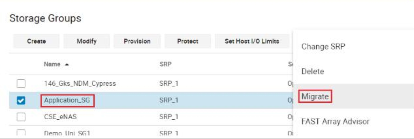
Figure 95. Migrate Storage Group Unisphere for PowerMax
As before, select the Storage Group to be migrated and start the NDM create operation. For further guidance on how to migrate the SG, see the section Metro-based NDM Walkthrough Guide.
In this example, the Storage Group view shows that the migration is 13% completed. In the previous version of NDM, it would have been necessary to let the migration complete to 100% before setting up DR.
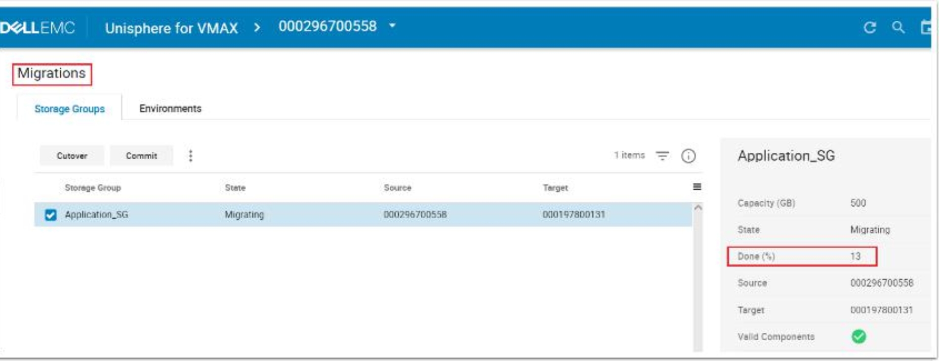
Figure 96. Viewing Migration Copy Progress Unisphere for PowerMax
From the target array, navigate to the Storage Group, highlight it, and select Protect.

Figure 97. Protect Migrating Storage Group Unisphere for PowerMax

Figure 98. Data Protection Wizard Unisphere for PowerMax
In the pop-up window, click Remote Replication using SRDF and click Next.
In the protection configuration window, select the target array, the SRDF mode, and the remote storage group name.
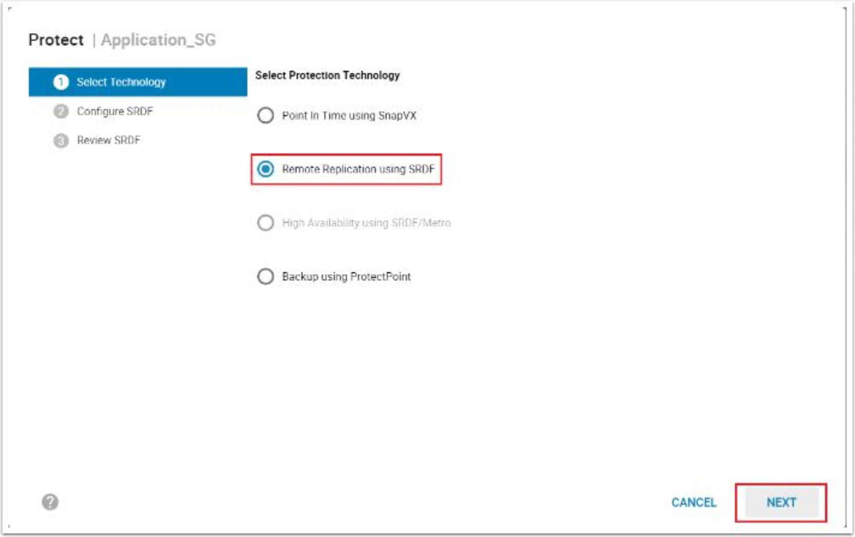
Figure 99. Data Protection Wizard, Protection Selection
The final confirmation of the planned configuration is displayed. Review and click Run Now.
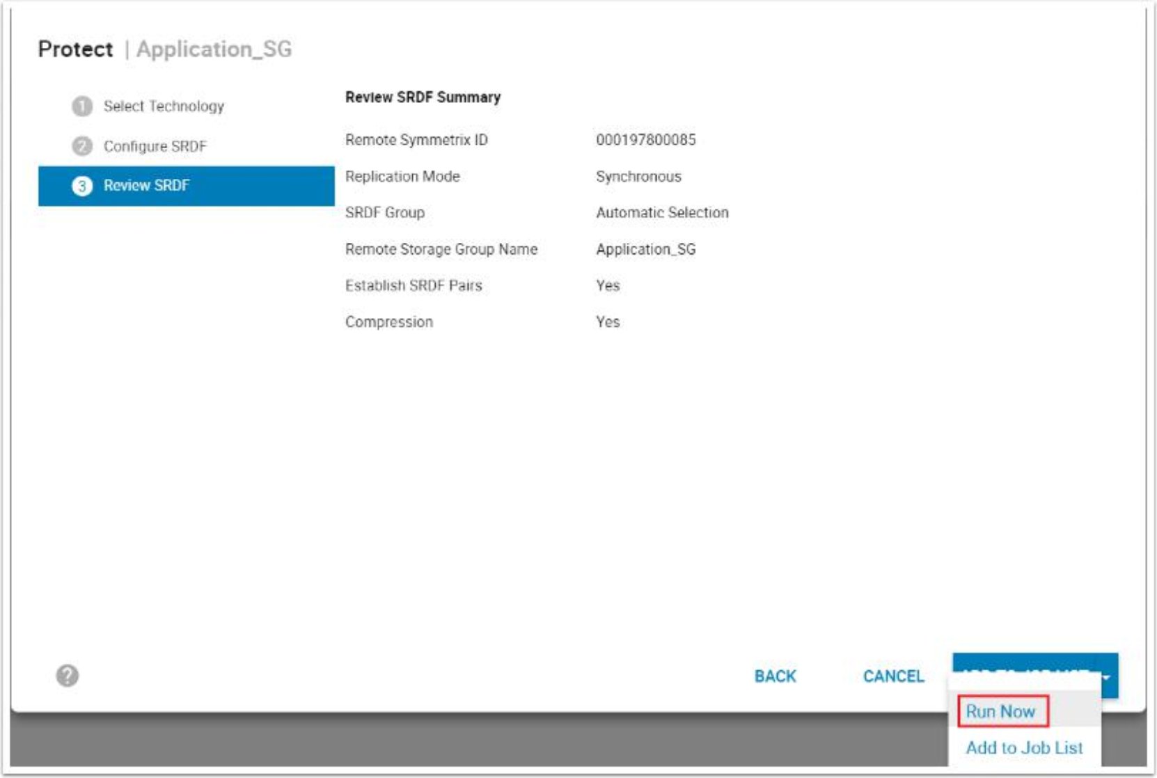
Figure 100. Data Protection wizard Review and Execute
The result is an SG with DR in an Active/Bias and Synchronous RDF state. Essentially, this cascaded R21 with the R1 being the NDM Source and the R2 being the new DR to 085. For guidance on how to continue with the migration, see the section Metro-based NDM Walkthrough Guide.

To achieve the same result with Solutions Enabler, perform the following:
- Create an SRDF group between the NDM target and planned Disaster Recovery site:
symrdf addgrp -label DrSite1 -rdfg 3 -sid 131 -dir 1F:30,2F:30 -remote_rdfg 3 -remote_sid 085 - remote_dir 1F:31, 2F:31
- Create the SRDF pairings using the following:
symrdf -file srdf.txt -sid 131 -rdfg 3 -type r1 -establish createpair where the srdf.txt file contains the device pairings
In this SRDF query, the RDFG is shown as 3 which shows that it is on the second leg of the R21. The devices on the DR target are Write disabled to the host and are Synchronized. Some other information such as the 'S' under the mode (M) signifies Synchronous mode.
