
Path management
Path management
-
Path failover and load balancing in VMware vSphere environments
The ability to dynamically multipath and load balance by using the native or third-party storage vendor multipathing software is available in VMware vSphere. The Pluggable Storage Architecture (PSA) is a modular storage construct. It allows storage partners (such as Dell with PP/VE (Virtual Edition)) to write a plug-in to best leverage the unique capabilities of their storage arrays. These modules can interface with the storage array to continuously resolve the best path selection. They can also use redundant paths to greatly increase the performance and reliability of I/O from the ESXi host to storage.
The use of PP/VE is a Dell best practice with VMware due to its superior ability to manage traffic and detect anomalies. Dell understands that many companies will choose to use NMP, particularly with the future deprecation of PP/VE. Both NMP and PP/VE will be discussed in the next sections.
Note: While PP/VE is no longer sold, it will be supported through July 2027 for those customers who currently license it. See KB 000223522 for more detail.
Native Multipathing plug-ins
By default, the native multipathing plug-in (NMP) supplied by VMware is used to manage I/O for non-NVMeoF devices (such as iSCSI, FC). NMP can be configured to support fixed and round robin (RR) path selection policies (PSP). Also, Dell supports the use of Asymmetrical Logical Unit Access (ALUA), though only with the Mobility ID.
Note: Dell Technologies does not support using the MRU PSP for NMP with PowerMax.
NMP is not supported for NVMeoF. VMware uses a different plug-in that is called the High-Performance Plug-in (HPP). This plug-in has been developed for NVMe devices, though it is only the default for NVMeoF devices. For local NVMe devices, NMP is the default, though it can be changed to use HPP through claim rules. HPP only supports ALUA with NVMeoF devices.Unlike with NMP, creating a different claim rule for these devices is unnecessary, as HPP is designed for ALUA. To support multipathing, HPP uses the Path Selection Schemes (PSS) when selecting physical paths for I/O requests as opposed to the PSP of NMP. HPP supports the following PSS mechanisms:
- Fixed
- LB-RR (Load Balance - Round Robin)
- LB-IOPS (Load Balance - IOPs)
- LB-BYTES (Load Balance - Bytes)
- Load Balance - Latency (LB-Latency)
NMP and other multipathing plug-ins are designed to co-exist on an ESXi host; nevertheless, multiple plug-ins cannot manage the same device simultaneously. To address this issue, VMware created the concept of claim rules. Claim rules are used to assign storage devices to the proper multipathing plug-in (MPP). When an ESXi host boots or performs a rescan, the ESXi host discovers all physical paths to the storage devices visible to the host. Using the claim rules, the ESXi host determines which multipathing module is responsible for managing a specific storage device. Claim rules are numbered. For each physical path, the ESXi host processes the claim rules starting with the lowest number first. The attributes of the physical path are compared with the path specification in the claim rule. If there is a match, the ESXi host assigns the MPP specified in the claim rule to manage the physical path.
This assignment process continues until all physical paths are claimed by an MPP. Figure 44 has a sample claim rules list with only NMP installed.
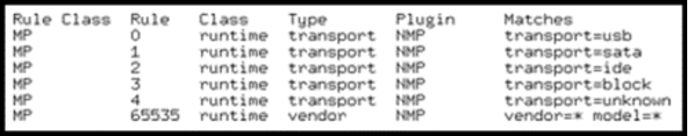
Figure 44. Default claim rules with the native multipathing module
SATP
VMware uses the concept of Storage Array Type Plug-ins (SATP) which are submodules of NMP. While VMware offers several generic SATPs, each vendor has their own SATP in the ESXi code. The SATP for PowerMax arrays is named VMW_SATP_SYMM. When VMware recognizes a device is from one of these arrays, it is assigned this SATP. Each Dell array has their own SATP. Note, however, VMware is moving away from this model and asking vendors to use the generic SATPs.
Claim Rules
If changes to the claim rules are needed after installation, devices can be manually unclaimed. If I/O is not running on the device, the rules can be reloaded without a reboot. For instance, the device can contain a mounted VMFS volume but it cannot contain running virtual machines. It is a best practice to make claim rule changes after installation but before the immediate postinstallation reboot. An administrator can choose to modify the claim rules, for instance, in order to have NMP or HPP manage Dell or non-Dell devices. Importantly, after initial installation of an MPP, claim rules do not go into effect until after the vSphere host is rebooted. For instructions on changing claim rules, consult the PP/VE for VMware vSphere Installation and Administration Guide at the Dell support site. Or, see the VMware vSphere SAN Configuration Guide available from the VMware website.
ALUA and the Mobility ID with NMP
As mentioned, the default SATP for PowerMax is VMW_SATP_SYMM. VMware assigns this SATP to any PowerMax device (except NVMeoF devices) unless different claim rules are added. This situation can be problematic when using the Mobility ID (MID) for devices.
Note: The Mobility ID (MID) is a format of device identifier that provides a universally unique volume identifier.
While the default SATP can be used with the MID, it can cause problems in two particular configurations: RDMs for Red Hat GuestOS and SRDF/Metro. In these configurations, it is essential to use ALUA. SRDF/Metro does not support using the VMW_SATP_SYMM SATP with the MID.
To assign the other SATP to MID devices, a new claim rule is necessary for the VMware generic SATP for ALUA, VMW_SATP_ALUA. To add a rule:
- Issue the following command on each ESXi host that will have Mobility ID devices. Notice the use of Round Robin PSP (with best practice IOPS=1 as discussed below), not MRU. The description (-e) can be adjusted:
esxcli storage nmp satp rule add -V EMC -M SYMMETRIX -s VMW_SATP_ALUA -c tpgs_on -P VMW_PSP_RR -O iops=1 -e “VMAX ALUA rule for Mobility IDs”
- Reboot the ESXi host to complete the configuration. Any existing and new MID devices are assigned the ALUA SATP instead of the default.
Note: PP/VE automatically detects the Mobility ID and assigns those devices to its ALUA policy. Therefore, when using this path management software, no changes are required. Only default NMP requires manual intervention on each ESXi host.
HPP Path Selection Schemes
The High-Performance Plug-in uses Path Selection Schemes (PSS) to manage multipathing exactly as NMP uses PSP. As noted above, HPP offers the following PSS options:
- Fixed—Use a specific preferred path.
- LB-RR (Load Balance - Round Robin)—The default PSS. After 1000 IOPs or 10,485,760 bytes (whichever comes first), that path is switched in a round robin fashion. This option is the equivalent of NMP PSP RR.
- LB-IOPS (Load Balance - IOPs)—When 1000 IOPs are reached (or set number), VMware switches to the path which has the least number of outstanding I/Os.
- LB-BYTES (Load Balance - Bytes)—When 10 MB are reached (or set number), VMware switches to the path which has the least number of outstanding bytes.
- Load Balance - Latency (LB-Latency)—This mechanism is the same as the mechanism available with NMP. VMware evaluates the paths and decides which has the lowest latency.
Because the PSSs LB-IOPS, LB-BYTES, and Load Balance offer intelligence, they are superior PSSs to LB-RR or Fixed. As performance is paramount for NVMeoF, Dell Technologies recommends using the Load Balance PSS, or LB-Latency. It offers the best chance at uniform performance across the paths.
To set the PSS on an individual device, issue the following as seen in Figure 45:
esxcli storage hpp device set -P LB-Latency -d eui.04505330303033380000976000019760
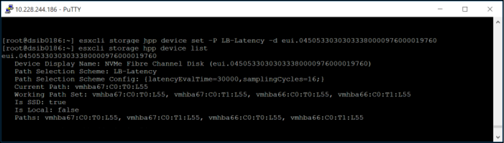
Figure 45. Setting PSS LB-Latency on FC-NVMe device
To add a claim rule so that this PSS is used for every NVMeoF device (FC or TCP) on a PowerMax 8000 at reboot, issue the following command:
esxcli storage core claimrule add -r 914 -t vendor --nvme-controller-model='EMC PowerMax_8000' -P HPP --config-string "pss=LB-Latency"
You cannot pass the usual flag, model, because that field is restricted to 16 characters. The Dell PowerMax models are 17 characters (such as EMC PowerMax_8000). For cases like these, VMware offers the –nvme-controller-model flag, which is used here. Be sure to adjust the model to match the PowerMax array.
A reboot is required for current devices. However, if the new claim rule is loaded by issuing the following, any future devices that are masked to the host have the new setting:
esxcli storage core claimrule load
Latency threshold setting
By default, every I/O that passes through ESXi, goes through the I/O scheduler. It is possible that because of the speed of NVMe, using the scheduler might create internal queuing, thus slowing down the I/O. VMware offers the ability to set a latency threshold so that any I/O with a response time below the threshold bypasses the scheduler. When this mechanism is enabled, and the I/O is below the threshold, the I/O passes directly from PSA through the HPP to the device driver.
For the mechanism to work, the observed average I/O latency must be lower than the set latency threshold. If the I/O latency exceeds the latency threshold, the I/O temporarily returns to the I/O scheduler. The bypass is resumed when the average I/O latency drops below the latency threshold again.
There are a couple different ways to set the latency threshold. To list the existing thresholds, issue:
esxcli storage core device latencythreshold list
To set the latency at the device level issue:
esxcli storage core device latencythreshold set -d eui.36fe0068000009f1000097600bc724c2 -t 10
To set it for all Dell NVMeoF devices on a PowerMax 8000 (adjust model based on array), issue the following command:
esxcli storage core device latencythreshold set -v 'NVMe' -m 'EMC PowerMax_8000' -t 10
These settings persist across reboot, but any new devices would require latencythreshold to be set on it.
Managing NMP in vSphere Client
Claim rules and claiming operations must all be done through the CLI. Choosing the NMP multipathing policy can be performed in the vSphere Client itself. By default, PowerMax devices that NMP and the SATP VMW_SATP_SYMM manage have the “Round Robin” policy set, which is a best practice. Round Robin uses an automatic path selection rotating through all available paths and enabling the distribution of the load across those paths.
Dell Technologies recommends adjusting the frequency of path changes which is covered next, but the Round Robin policy should not be adjusted. As there are customer use cases that might necessitate changing the policy, however, it is covered here for completeness. There are two methods to change the policy: CLI on the ESXi host, or UI (vSphere Client or Dell VSI).
The CLI can be run on each ESXi host by issuing the command:
esxcli storage nmp satp rule add -s VMW_SATP_SYMM -P VMW_PSP_RR -M SYMMETRIX
From then forward after reboot, all PowerMax devices will be, by default, set to Round Robin. Alternatively, each device can be manually changed in the vSphere Client as in Figure 46.
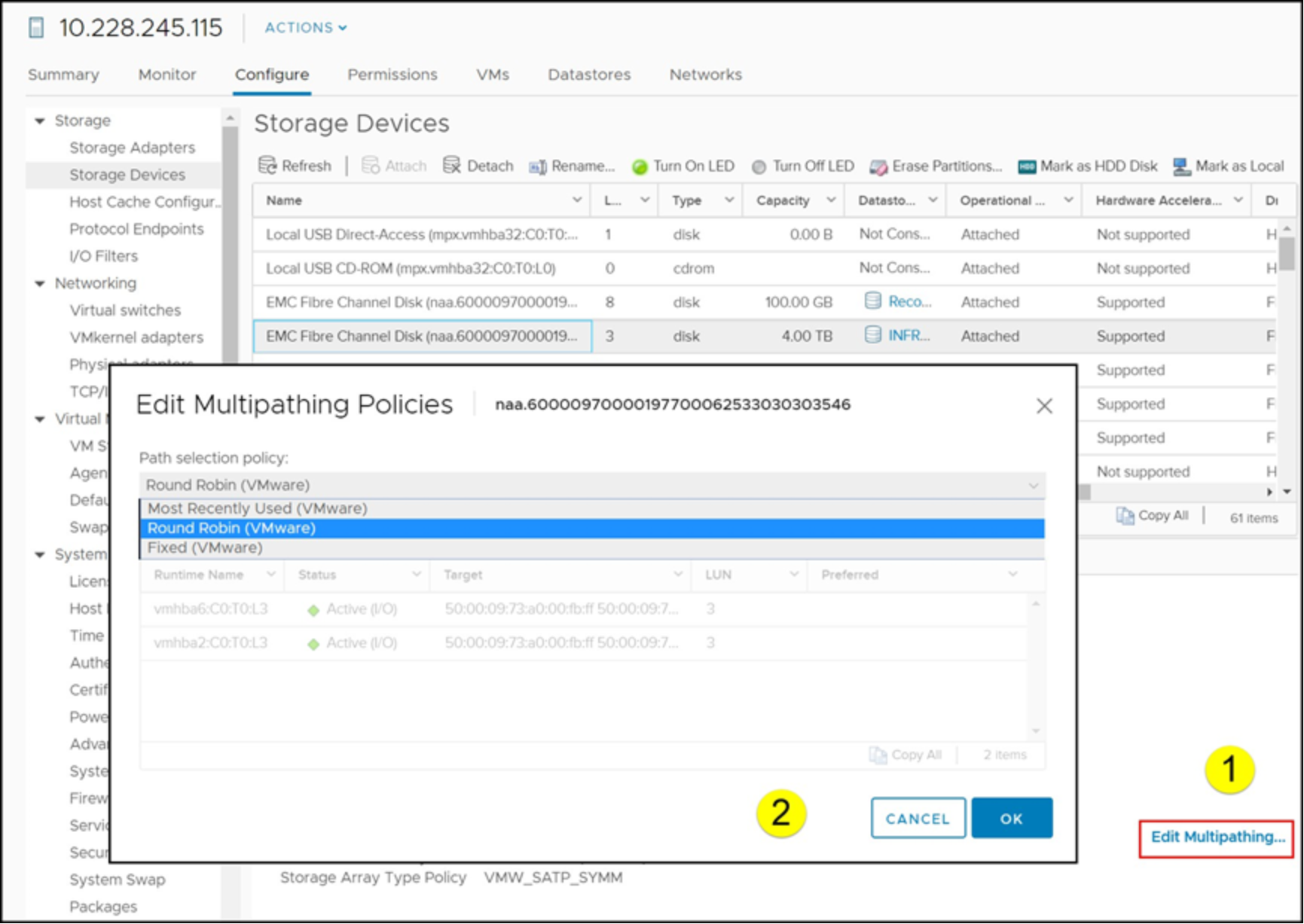
Figure 46. NMP policy selection in vSphere Client
A reboot is required for current devices. However, if the new claim rule is loaded by issuing the following, any future devices that are masked to the host have the new setting:
esxcli storage core claimrule load
Managing HPP in vSphere Client
Claim rules and claiming operations must all be done through the CLI. Choosing the HPP multipathing policy for NVMeoF devices can be performed in the vSphere Client itself. By default, PowerMax NVMeoF devices that HPP manages have a PSS set to the policy of LB-RR. This method is not a best practice, so the PSS can be changed to LB-Latency with either the CLI or the vSphere Client. With the CLI, run the following command for each device:
esxcli storage hpp device set -P LB-Latency -d <device_id>
Alternatively, each device can be manually changed in the vSphere Client as in Figure 47.
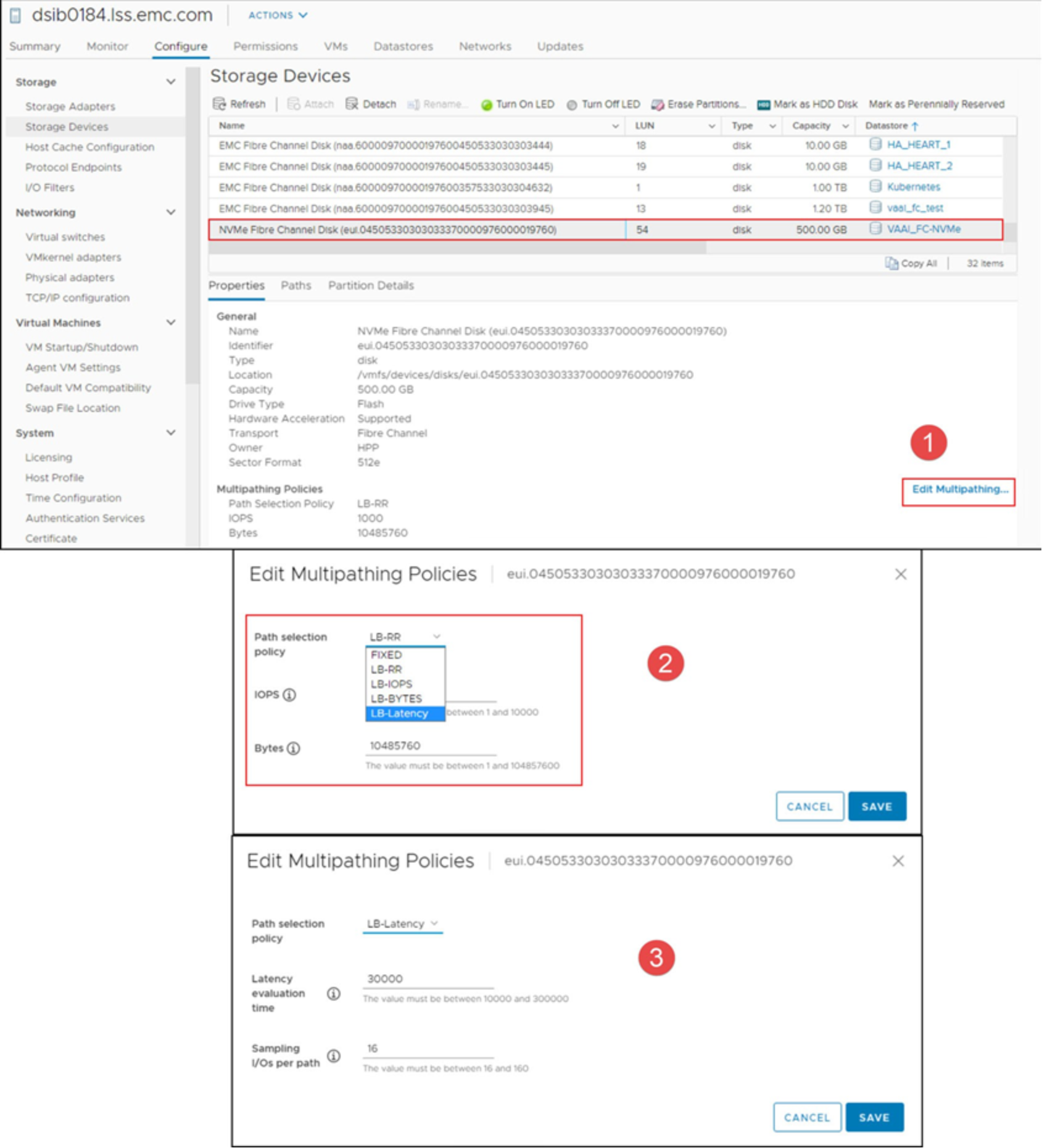
Figure 47. HPP policy selection in vSphere Client
Dell VSI offers the ability to set the best practices for all NVMeoF devices on a host or cluster under the ESXi Host Settings menu. It is possible to update existing devices and add a rule for future ones. The interface for doing so is shown in Figure 48 for the vSphere Client.
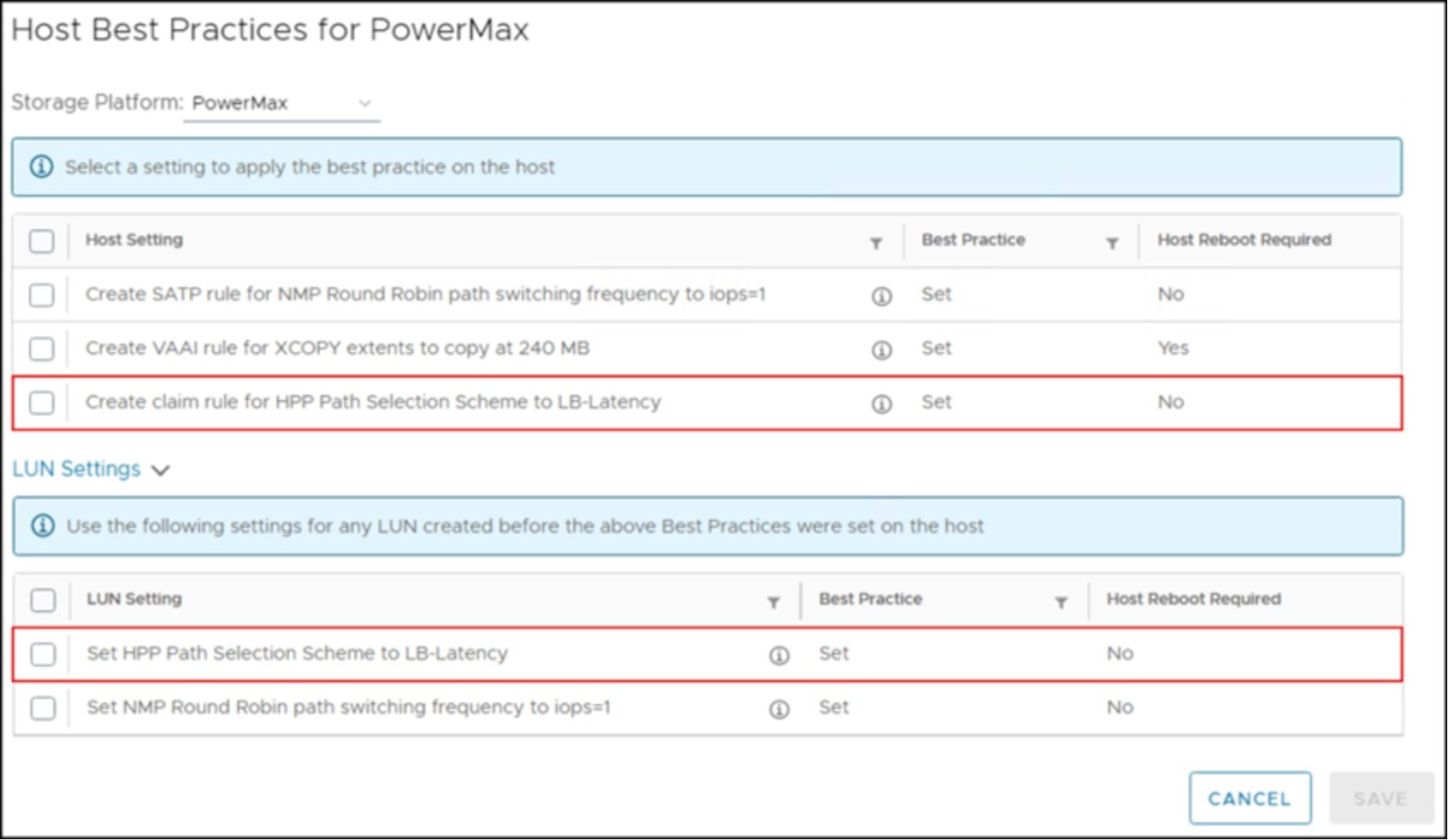
Figure 48. VSI HPP Host Recommended Settings - vSphere Client
NMP Round Robin and the I/O operation limit
The NMP Round Robin path selection policy has a parameter that is known as the “I/O operation limit.” This parameter controls the number of I/Os sent down each path before switching to the next path. The default value is 1000, so NMP defaults to switching from one path to another after sending 1000 I/Os down any given path. Tuning the Round Robin I/O operation limit parameter can significantly improve the performance of certain workloads, markedly so in sequential workloads. With environments which have random and OLTP type 2 workloads in their environments, setting the Round Robin parameter to lower numbers still yields the best throughput.
Dell Technologies recommends that the NMP Round Robin I/O operation limit parameter be set to 1 for all PowerMax devices. Doing so ensures the best possible performance regardless of the workload being generated from the vSphere environment.
This setting is per device. In addition, setting it on one host does not propagate the change to other hosts in the cluster. Therefore, it must be set for every claimed PowerMax device on every host. For all new, unclaimed devices, however, a global value can be set to ensure that the operation limit is set on claiming. This method is also true if a claimed device is unclaimed and reclaimed.
- To set the I/O Operation limit as a rule (to be completed on each ESXi host):
esxcli storage nmp satp rule add -s "VMW_SATP_SYMM" -V "EMC" -M SYMMETRIX" -P "VMW_PSP_RR" -O "iops=1"
To set the limit on claimed devices:
- To check the I/O Operation limit on claimed devices:
esxcli storage nmp psp roundrobin deviceconfig get --device=<device NAA>
- To set the I/O Operation limit on claimed devices:
esxcli storage nmp psp roundrobin deviceconfig set --device=<device NAA> --iops=1 --type iops
This parameter cannot be altered using the VMware vSphere Client capabilities as it is a CLI-only operation. A reboot is still required to apply the new limit to claimed devices. To ensure that future devices receive the new limit before the reboot, issue the following command:
esxcli storage core claimrule load
Dell VSI offers the ability to set the I/O Operation limit to 1 for all devices on a host or cluster under the ESXi Host Settings menu. It is also possible to add the rule previously mentioned. The interface for doing so is shown in Figure 49 for the vSphere Client.
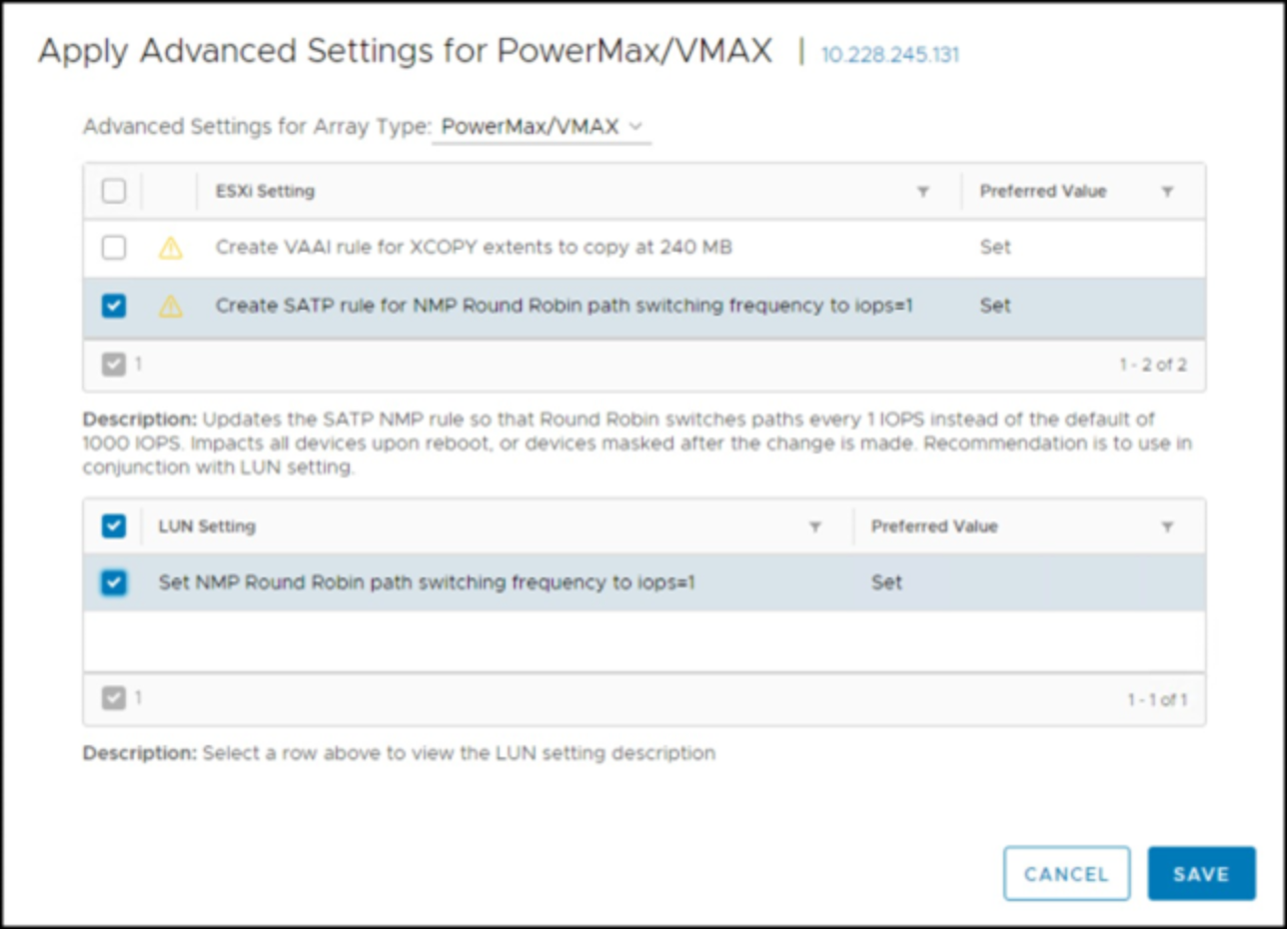
Figure 49. VSI NMP Host Recommended Settings - vSphere Client
NMP latency
VMware offers another type of Round Robin NMP called “latency” which was covered for HPP above. The capability enables VMware to test the performance of the paths to a device and route I/O appropriately. The feature is known as Latency Round Robin. While Dell still recommends using Round Robin with the I/O Operation limit set to 1, it is acceptable to use this latency instead if pertinent.
NMP latency should be used when running an SRDF/Metro vMSC uniform (cross-connect) configuration. Note, however, best practice for SRDF/Metro vMSC is a nonuniform configuration where the local hosts only see the local array. Cross-connect frequently results in lower performance. For more detail including implementation steps, see Best Practices for Using Dell SRDF/Metro in a VMware vSphere Metro Storage Cluster.
PP/VE Multipathing Plug-in and management
Dell PP/VE delivers PowerPath multipathing features to optimize VMware vSphere environments. PP/VE uses a command set, called rpowermt, to monitor, manage, and configure PP/VE for vSphere.
The syntax, arguments, and options are similar to the traditional powermt commands that are used on all other PowerPath multipathing supported operating system platforms. There is one significant difference in that rpowermt is a remote management tool.
ESXi does not have a service console. There is a limited CLI available on ESXi if Tech Support mode is enabled.
In order to manage an ESXi host, customers can use vCenter Server or CLI on a remote server. PP/VE for vSphere uses the rpowermt command-line utility for ESXi. The tools that contain the CLI can be installed on a Windows or Linux server or run directly on the PP/VE virtual appliance.
PP/VE for vSphere should not be managed on the ESXi host itself. There is also no option for choosing PowerPath within the Edit Multipathing Policies dialog within the vSphere Client as seen in Figure 46. Similarly, if PowerPath manages a device, no policy options are available for selection as seen in Figure 50. This case is true for any protocol. VMware defaults to MRU, but if an attempt is made to change the policy here, nothing occurs.
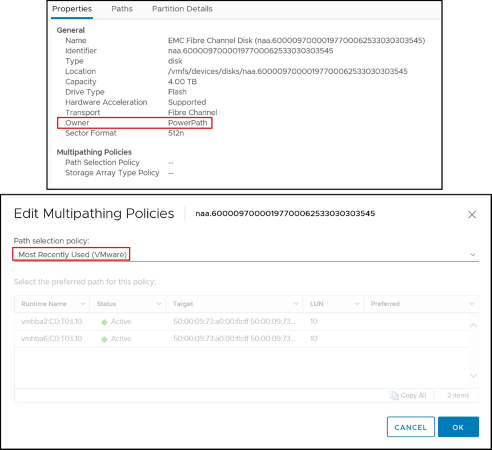
Figure 50. Manage Paths dialog viewing a device under PowerPath ownership
There is no local or remote UI for PowerPath on ESXi, so administrators should use the rpowermt utility. If using the PowerPath Management Appliance, however, it is possible to monitor the ESXi hosts paths. This UI is shown in Figure 51. The red box shows the FC-NVMe devices, and how PP/VE has recognized them as ALUA.
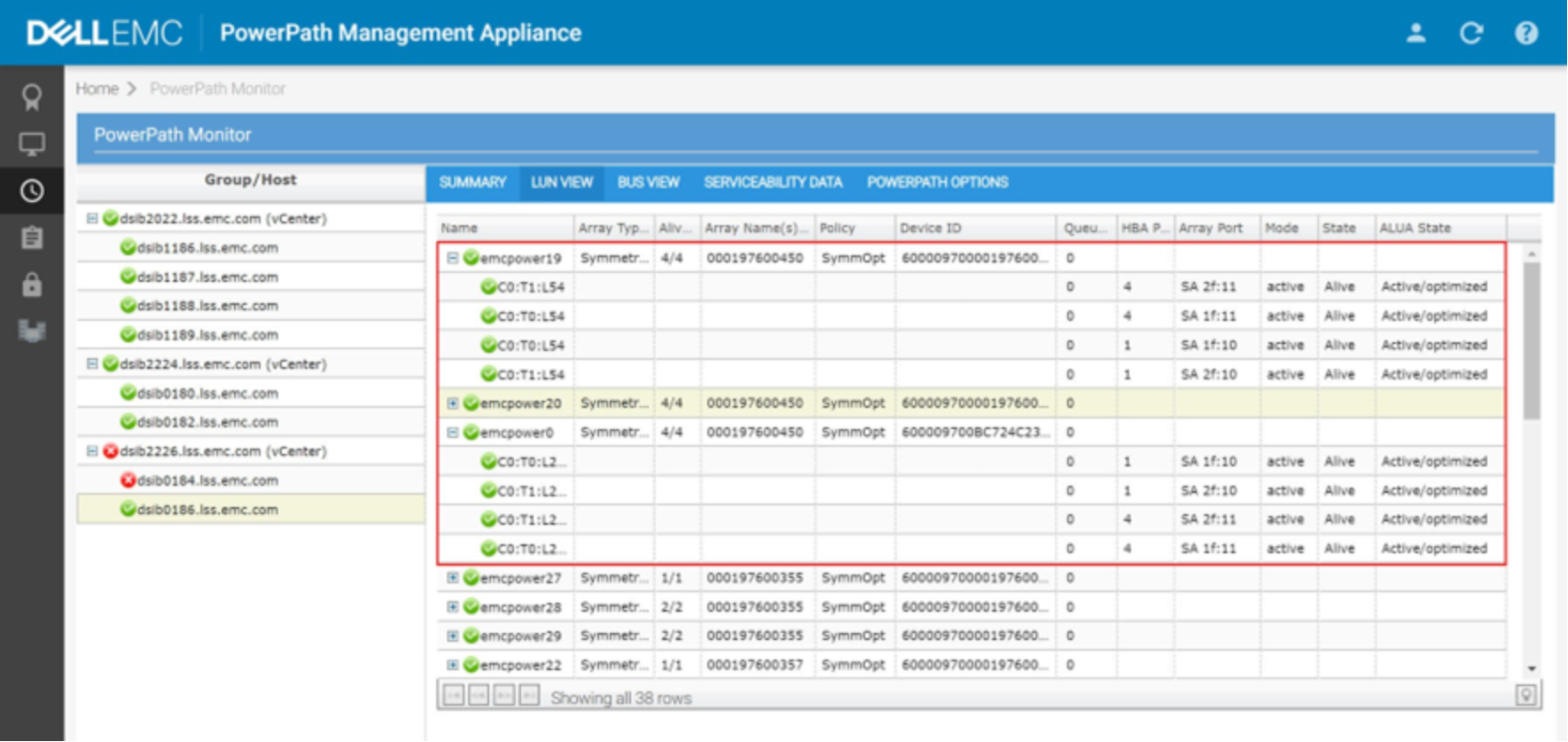
Figure 51. PowerPath Management Appliance
When the ESXi host is connected to a PowerMax array, the PP/VE kernel module running on the vSphere host associates all paths to each device presented from the array. It also associates a pseudo device name. An example is shown in Figure 52, which has the output of rpowermt display host=x.x.x.x dev=emcpower20. Note in the output that the device has four paths and displays the recommended, and default, optimization mode (SymmOpt = Symmetrix optimization).
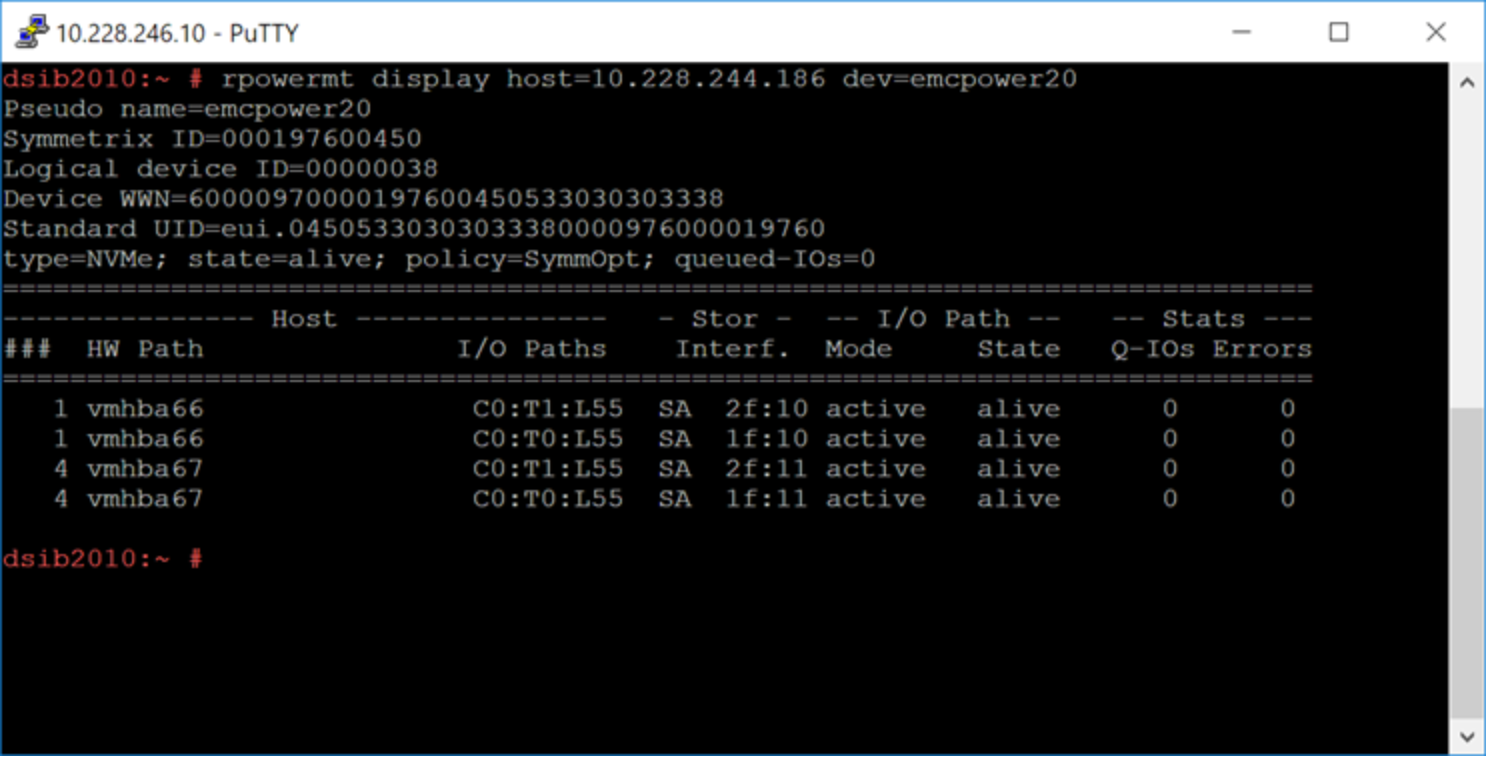
Figure 52. Output of the rpowermt display command on a PowerMax device
For more information about the rpowermt commands and output, consult the PP/VE for VMware vSphere Installation and Administration Guide.
As more PowerMax directors become available, the connectivity can be scaled as needed. PP/VE supports up to 32 paths to a device.
Note: ESXi supports 4096 total combined logical paths to all devices.
These methodologies for connectivity ensure that all front-end directors and processors are used. They provide maximum potential performance and load balancing for vSphere hosts that are connected to the PowerMax storage arrays with PP/VE.