
Pass-through NDM walkthrough guide (source running 5876 code)
Pass-through NDM walkthrough guide (source running 5876 code)
-
Using Unisphere for PowerMax
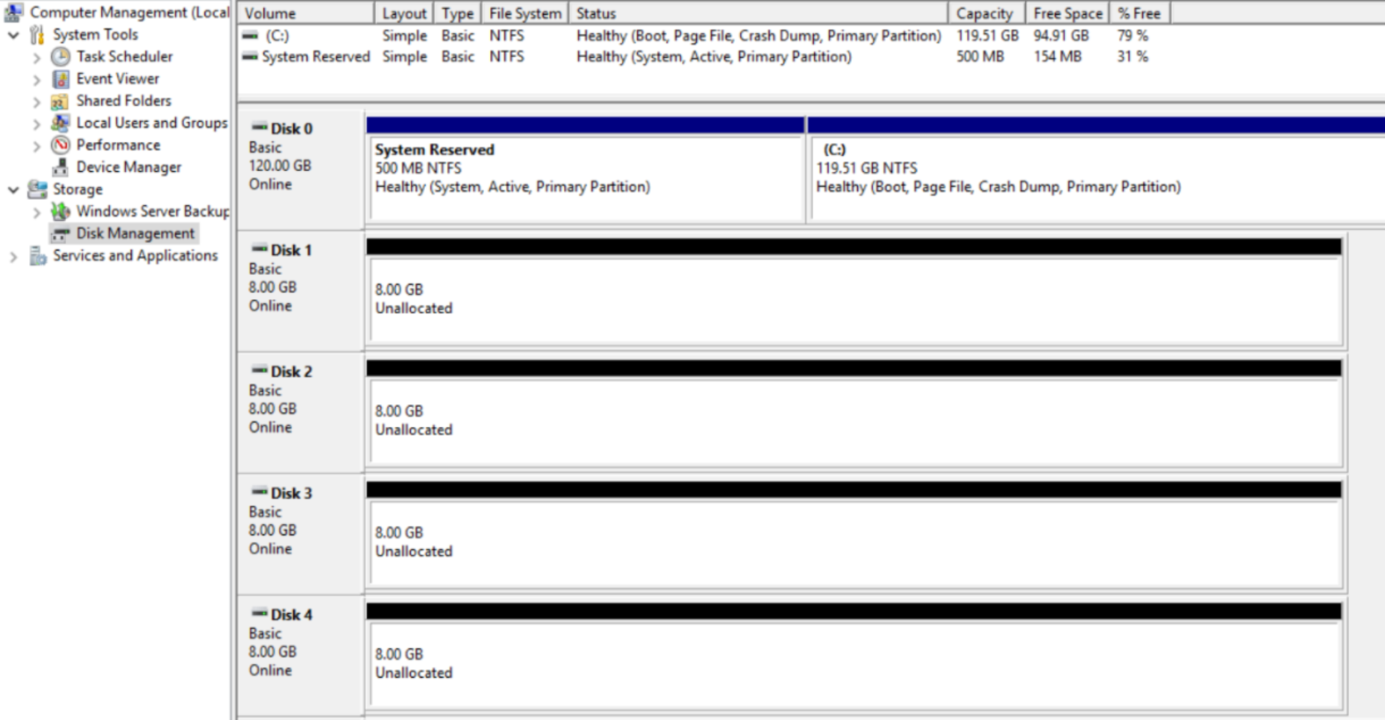
The following screenshots are taken from disk management on a Microsoft Windows Server 2016 host, this walkthrough intends to migrate disks 1 to 4 using NDM without any impact to the operating system or application accessing these devices. This is a virtual host with physical Raw Device Mappings.
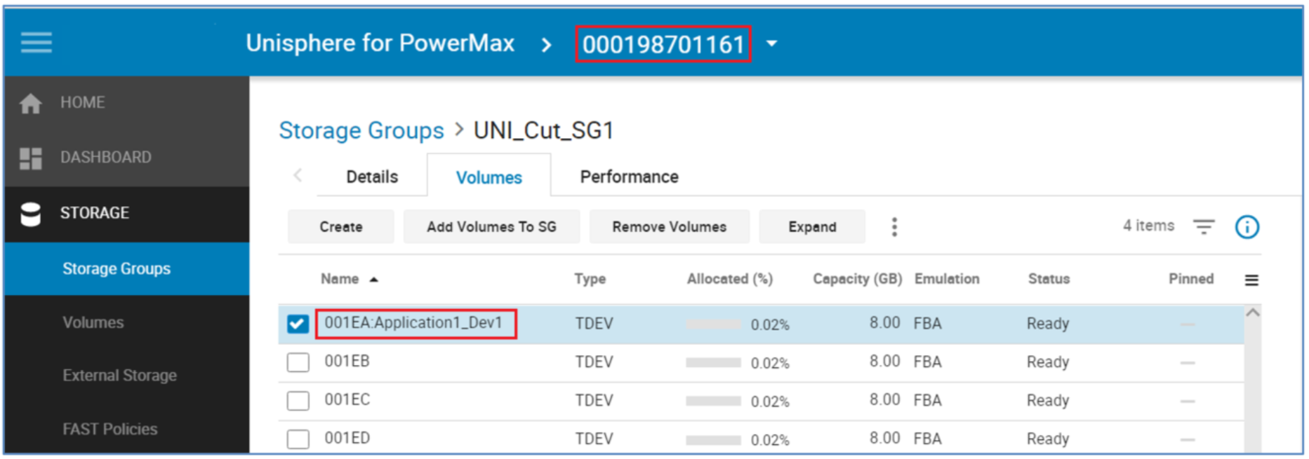
The VMAX devices involved in this example are 1EA through 1ED added to Storage Group Uni_Cut_SG1, which is masked to the virtual host.
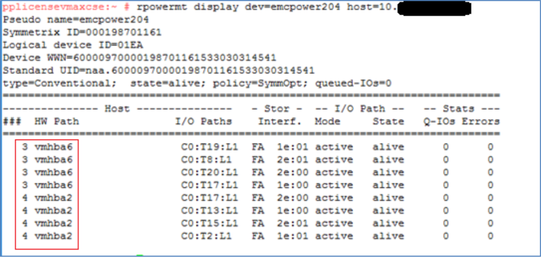
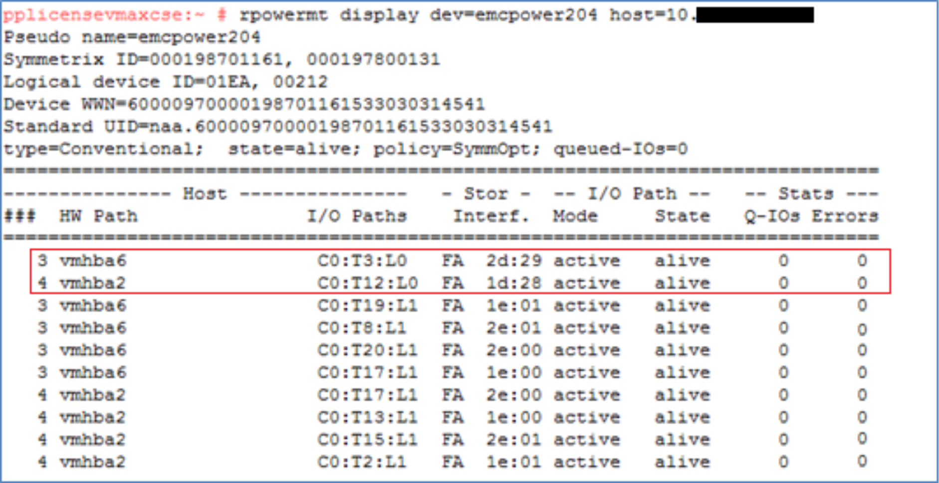
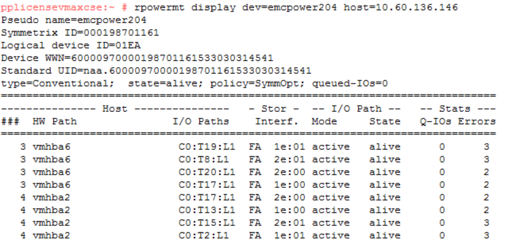
An example of the multipathing setup using device 1EA. It shows what the pathing looks like prior to the NDM create and the host rescan. For each of the four volumes here there are eight paths to the source array which are all alive and available for host use. At this point, there are no paths to the target array even though our zoning should be in place before the NDM create.
NDM environment setup
From the Unisphere Dashboard, select the Source array from the available arrays in the view. In this case, the source array is a 10K with the serial number ended in 161.
The Environment Setup configures the migration environment that will be required to migrate any application from the source array to the target array. It confirms that both the source and target arrays can support the NDM operations. This includes ensuring that a usable replication pathway for data migration is available between the source and target arrays and creating an SRDF group for the migration. The setup is run once only. When the migration pathways and SRDF group are configured, all storage groups on the source array can be migrated until all migrations from the source to the target have been completed.
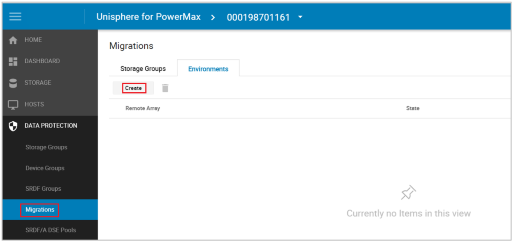
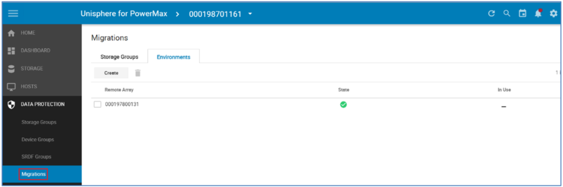
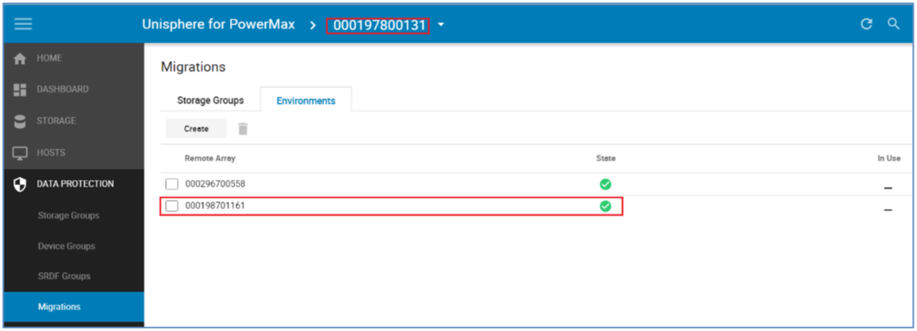
From the Data Protection menu select Migrations, Select the Environment tab and this will display any existing Environments already setup. The parameter In Use shows us if the Environment is validated and usable. The In Use parameter tell us if there is an active Migration using this environment.
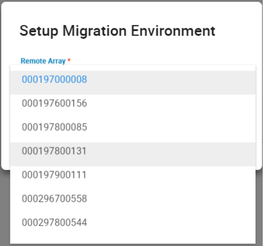
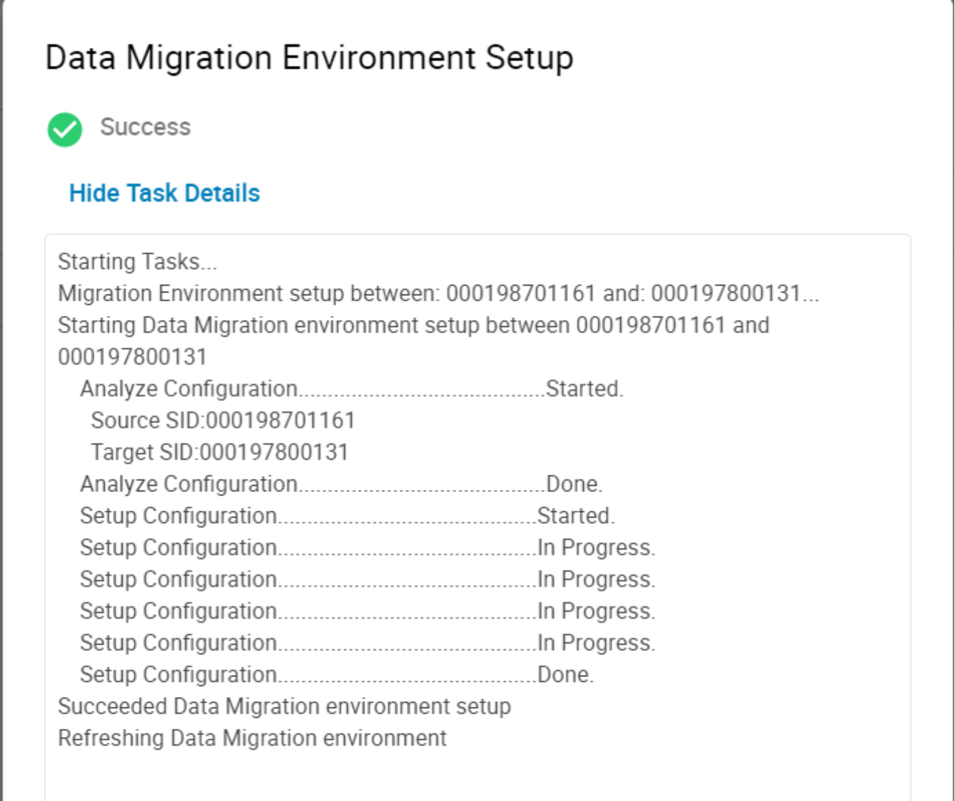
To create an environment, select Create, the pop-up window below allows the choice of target array. This is populated with suitable arrays. Should the required array not be present, verify the RDF zoning and confirm the intended target array is suitable and its current code level is within the support matrix. Select the relevant array and choose Run Now.
Examining the RDF environment from the new Topology view shows the RDF group template that has been created. Go to the Dashboard and Replication and hover over the line between our source and target. From here the SRDF Groups window appears. Select View Groups to display the SRDF group window highlighted below.
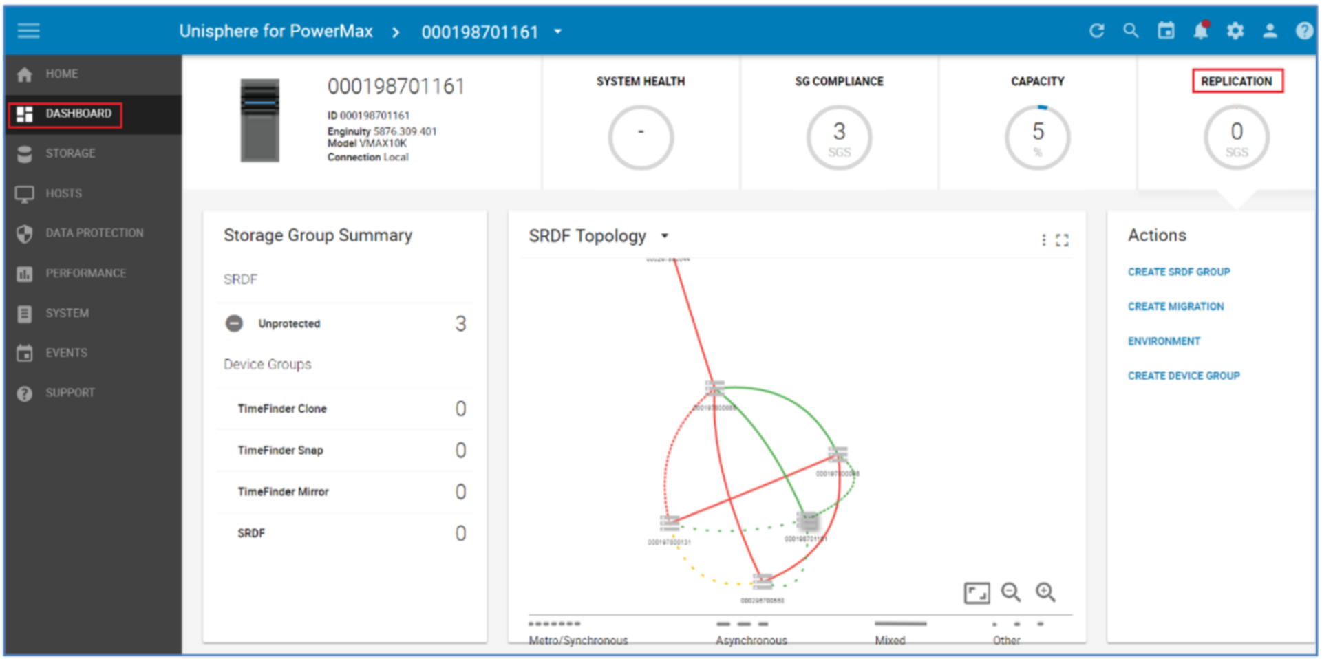
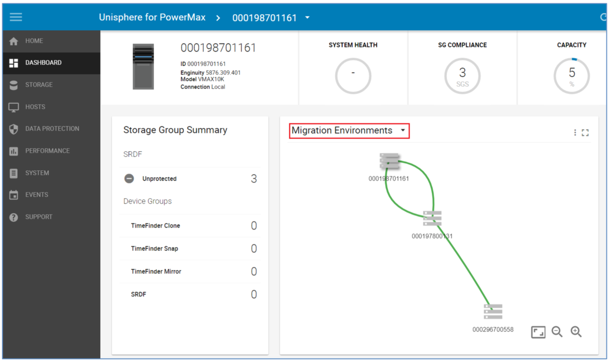
The dotted link between 161 and 131 suggest and “other” type of SRDF relationship. In this case, it is a migration link. The drop-down menu highlighted below allows the user to highlight just the migration relationships.
Now the Environment is in place we can continue with the NDM Create for the SG containing the application to be migrated.
Note: NDM Environment setup creates RDF links between the Source and Target using one port per Director for each zoned link. However, post-setup the user has the ability to add extra links manually using: symrdf modifygrp –rdfg 250 –add -dir xx –remote_dir xx
Create migration session
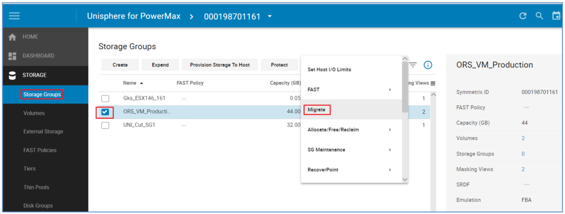
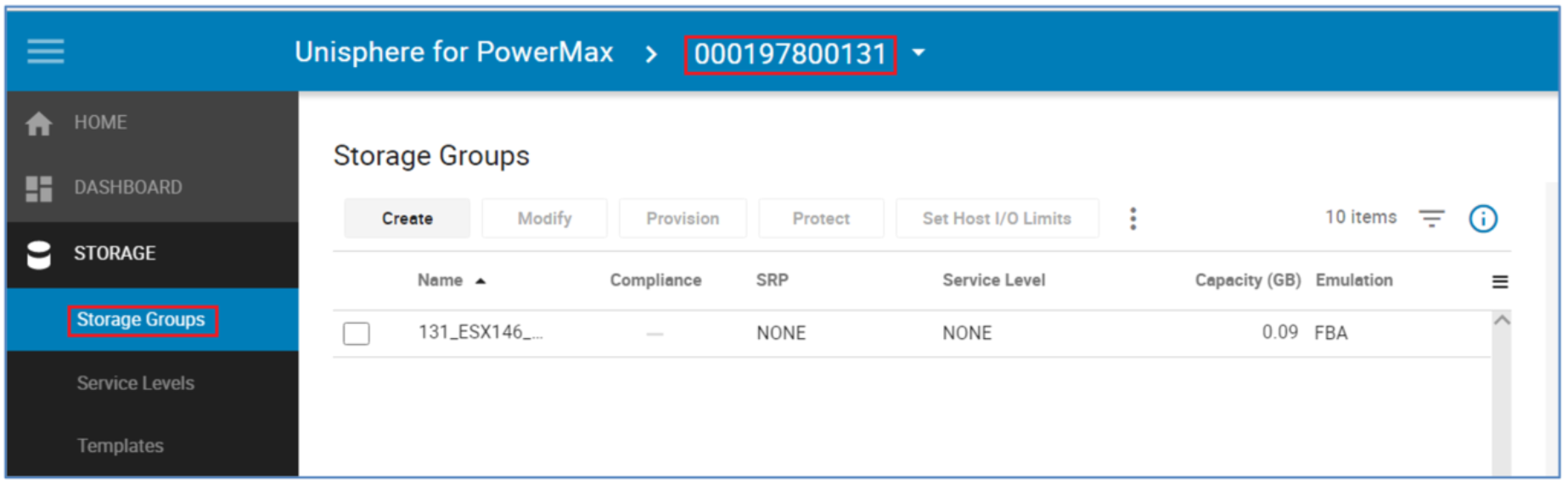
From the Storage tab select Storage Groups, from there locate the SG that is to be migrated. Set the check box and click the More Actions "3-Dot" icon to the right of Set Host I/O Limits. From the drop-down menu, select Migrate.
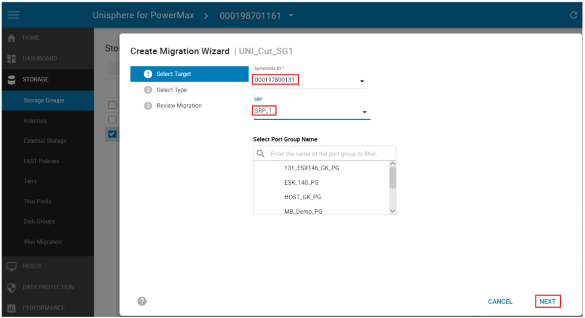
From the pop-up Create Migration Wizard, select the Target array (only Arrays with valid Environments setup appears on this drop-down menu). From Solutions Enabler 9.0 and later, the ability to select an existing Port Group on the target array is also an option. Select the target array SRP and Select Next.
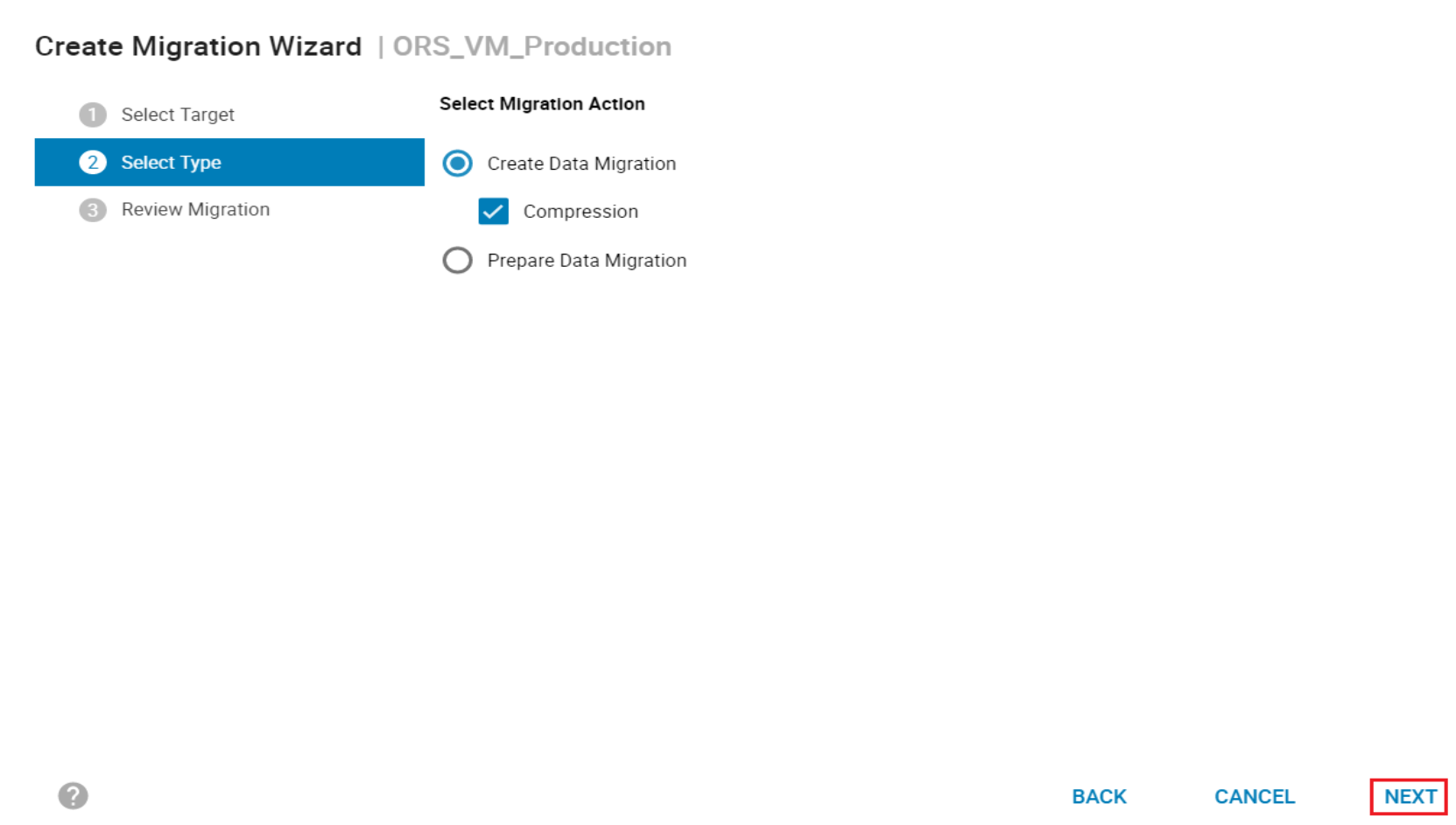
From the next screen select Create Data Migration, from here we have the option of selecting Compression on the target SG. The Prepare Data Migration selection requires Performance data to be collected on the host. This runs a check for resources on the target array to ensure the addition of the new SG does not cause the target array to exceed any performance metrics on both FE and BE. It will also produce a spread sheet to help plan the zoning required for the host from the target array.
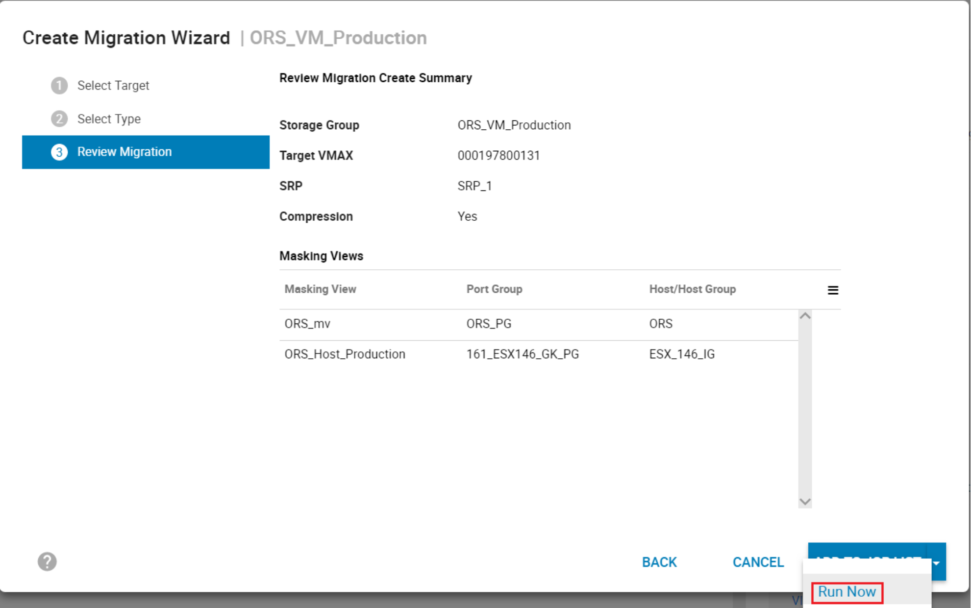
The final menu for the Wizard gives a final confirmation on the planned NDM session to be created. It breaks down the planned masking view elements and the NDM parameters. Select Run Now to continue.
Creating the NDM session will also validate the Environment as part of the setup to ensure the migration complete successfully. The Create Command:
- Creates a Storage Group on the Target array (group name must not be in use on the target array) with the same name as the Source SG
- Creates duplicate devices on the target array to match those on the Storage Group
- Creates an initiator group using Initiators with entries in the login history table
- Creates a Port group (if one does not already exist)
- Effective (external) WWNs of the device created on the target are copied from the WWNs of the host devices
- Creates a masking view to the host from the target array
Note: During a Cutover NDM migration, the source of the migration is an R2 or an R21 device (if there is existing SRDF DR replication from the source device) and the target is an R1 device. This is different than basic SRDF operations and is required to allow DR protection during a migration using a cascaded SRDF configuration.
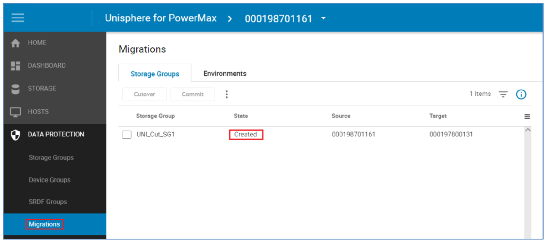
Examine the migration session
The following screenshot shows how to examine a migration session.
Perform a host rescan
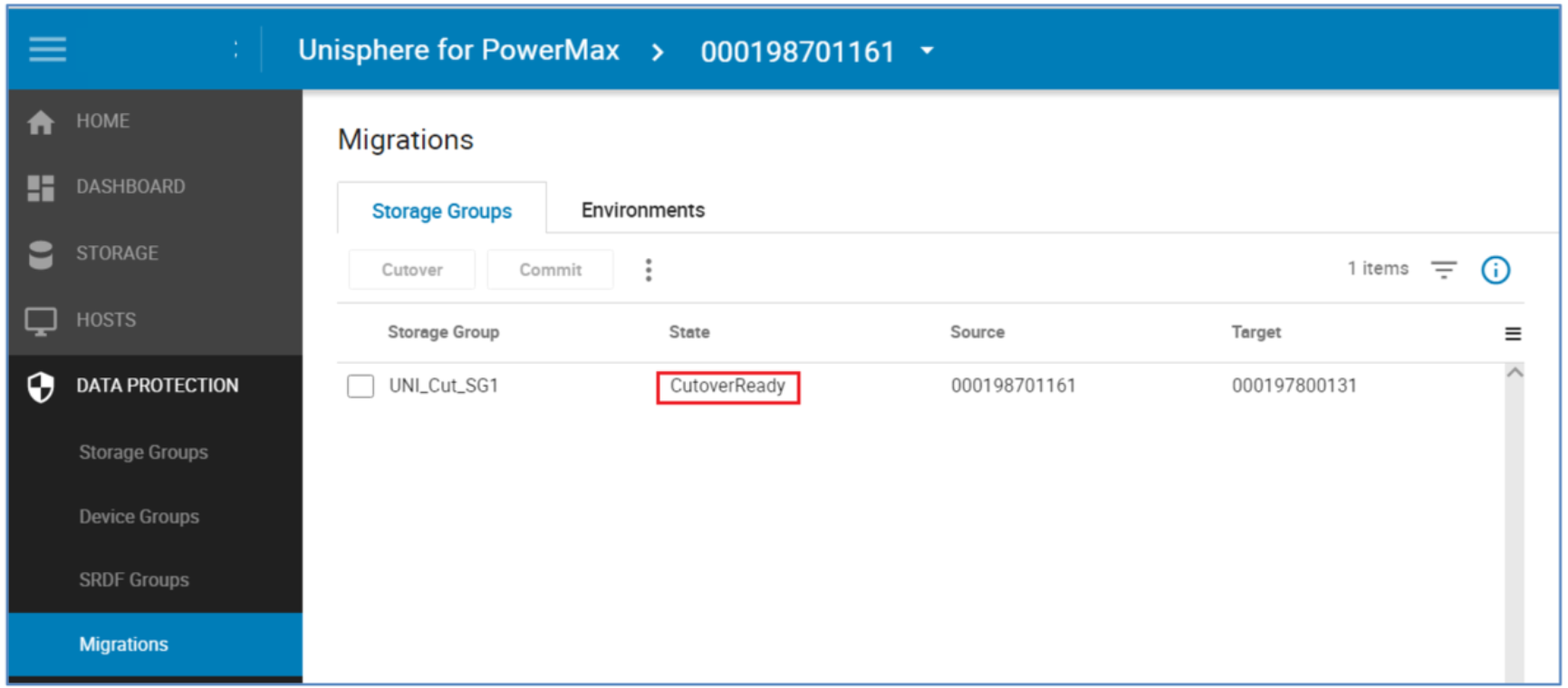
After the create operation completes the systems administrator must issue a host rescan to allow the host to discover the paths to the newly created devices. This host rescan is operating-system specific and also should include a rescan using the host multipathing software.
The NDM session goes from a Created state to a CutoverReady state after the host rescan is performed and the target devices are discoverable. After this is complete, I/O issued by the application will be directed to either the source or the target arrays through the host multipathing software. This is possible because the target devices are in pass-through mode. Appendix A: Host multipathing software notes has more details on host multipathing software settings.
CutoverReady and pass-through mode
Pass-through mode allows the host to write to or read from either the source or target array. Any write that in sent to the target array is sent over the SRDF link and serviced by the source array. No data is kept on the target array while in a CutoverReady state.
The CutoverReady state is a transitional state. The devices should only be in a CutoverReady state and using pass-through mode for as long as it takes to check that the Create has succeeded properly, to run the host rescan, and to run the Cutover operation.
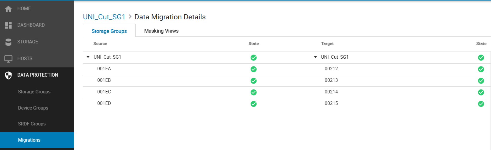
Double-clicking the NDM session displays the Migration Details view. This example below shows the individual devices involved in the session. Under the target tab we can see devices 200 through 203 have been created on the target side by the NDM create. The State also shows a live status of each of the devices involved. A device without a green tick should be investigated for potential problems before continuing.
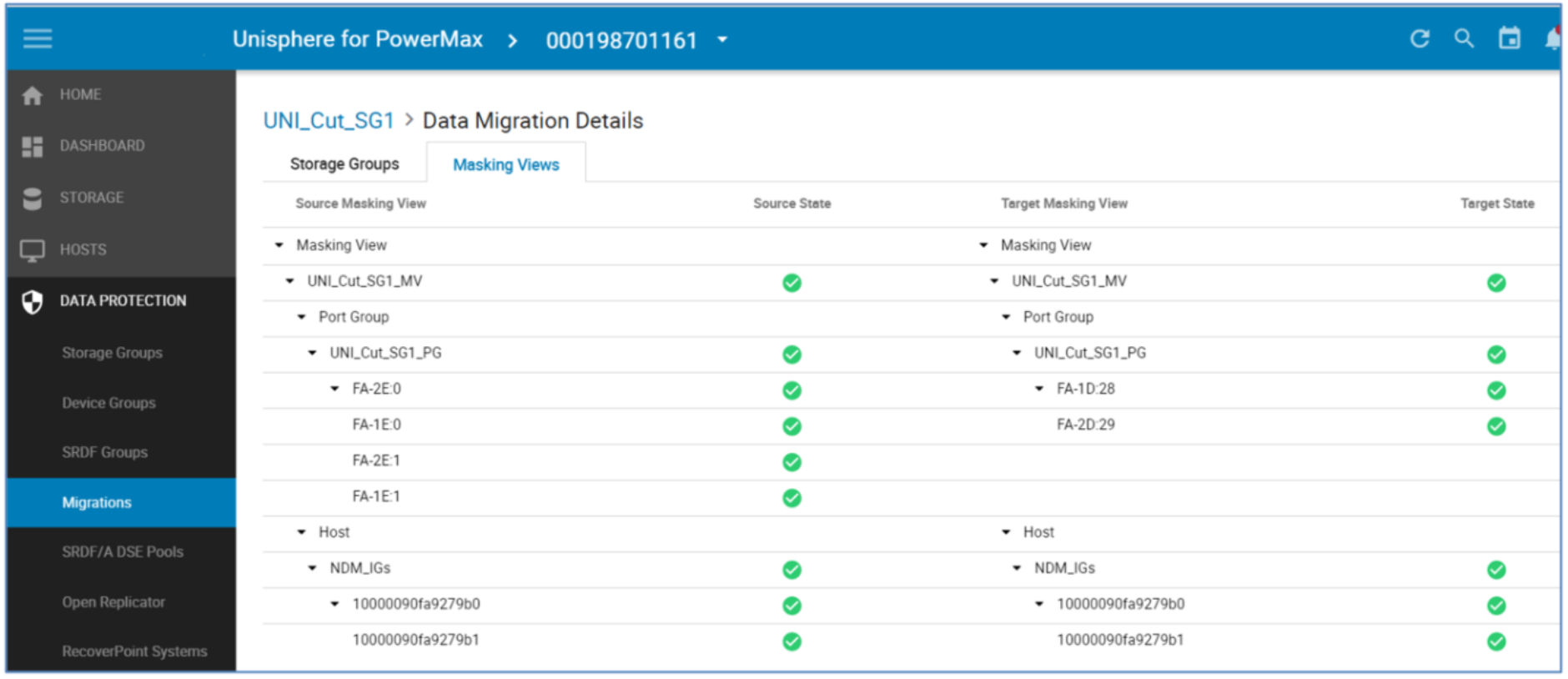
Selecting the Masking Views tab opens up the pane outlining the masking and masking elements involved on both sides of the NDM session. This screen is useful for troubleshooting any issues with the migration such as an unplanned or unauthorized manipulation of any of the NDM elements hindering the progress to the commit stage. This is highlighted in the State not showing a green tick.
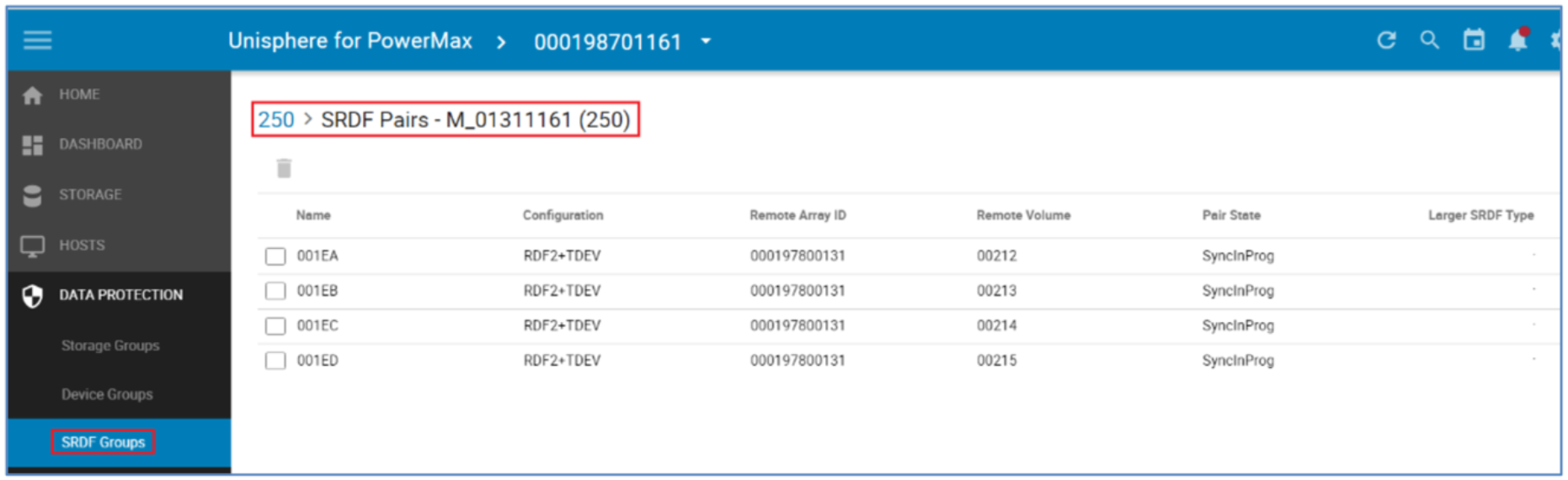
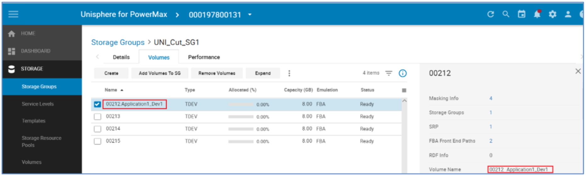
The SRDF Groups tab in Data Protection shows the SRDF relationships established as part of the Create Command. The Devices 212 to 215 in the example below have been created as replicas of the source devices on the target array. The SyncInProg state can be ignored in this case as the data transfer from Source to Target has yet to start.
View paths to new devices
Viewing the same device (1EA) from the multipathing software post rescan shows the highlighted extra paths online to the target array (in this case two extra paths) this depends on the zoning setup. It also displays the source and target SIDs and the device numbers involved for these paths. This highlights the WWNs on the LUNs to appear as a single device with just extra paths. Prior to version 6.2, PowerPath was not aware of the NDM process so the dual SIDs and devices IDs were not visible.
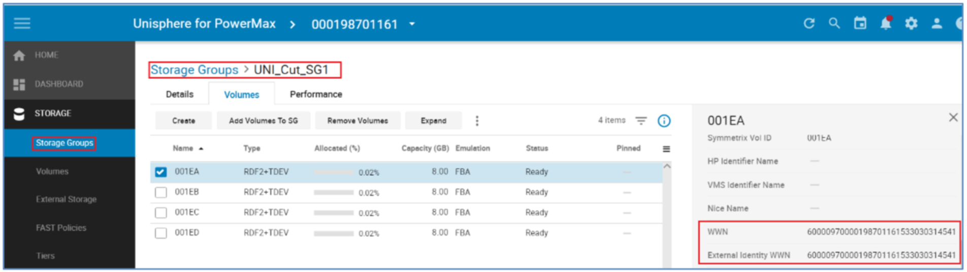
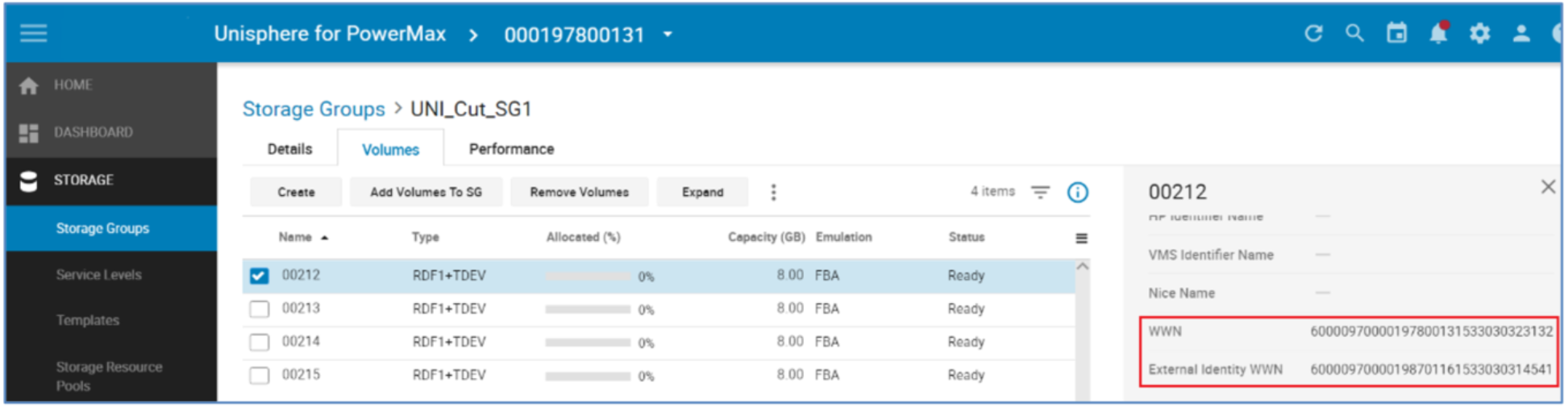
Examine IDs of source and target
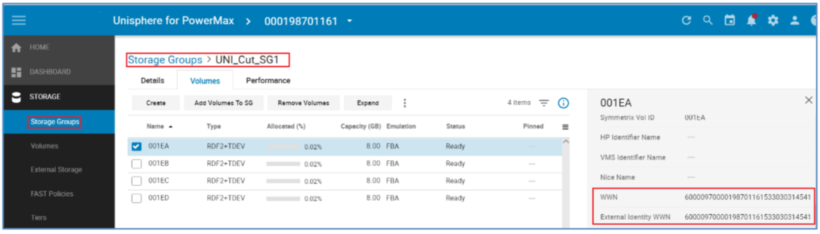
Viewing the devices WWNs after the Create process shows that the source device has a WWN and External (host visible) WWN with the same value. However, the target’s WWN and External WWNs differ. The target’s External WWN has inherited the WWN of the source in order to appear logically as the same device to the host and picked up my multipathing software as an extra path to the same device.

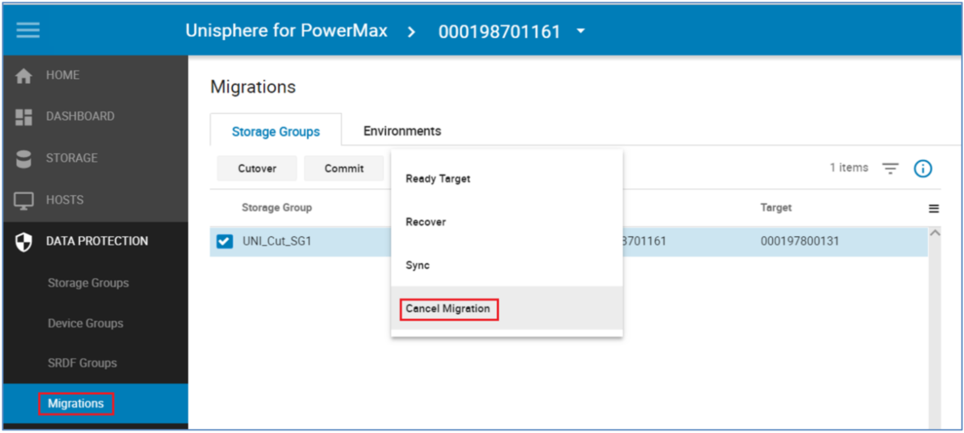
Cancel a migration
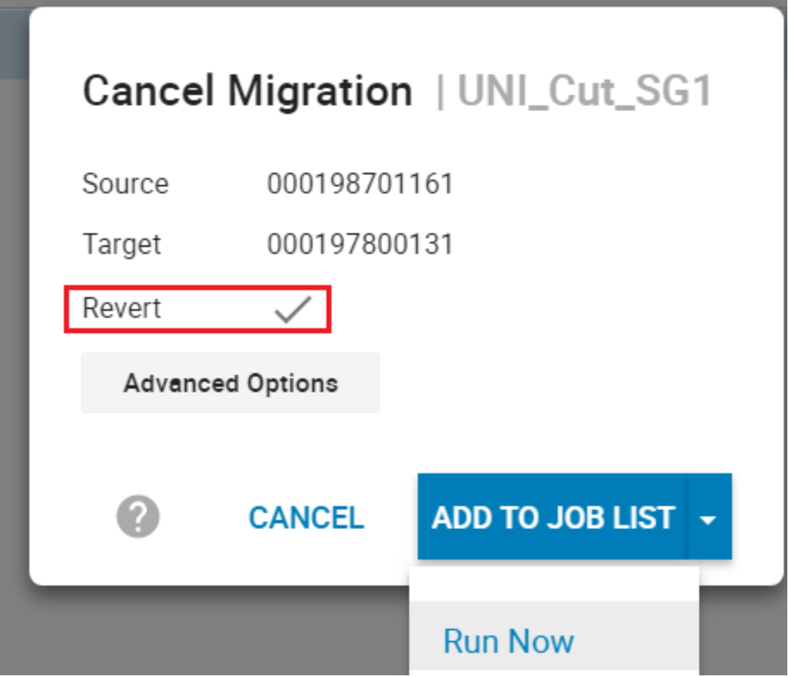
At any point before a commit operation is run on a Storage Group, a migration that has not been committed can be canceled. In this example, the Cancel command is occurring before the cutover. This operation does not require the –revert flag because processing has not moved to the target array.
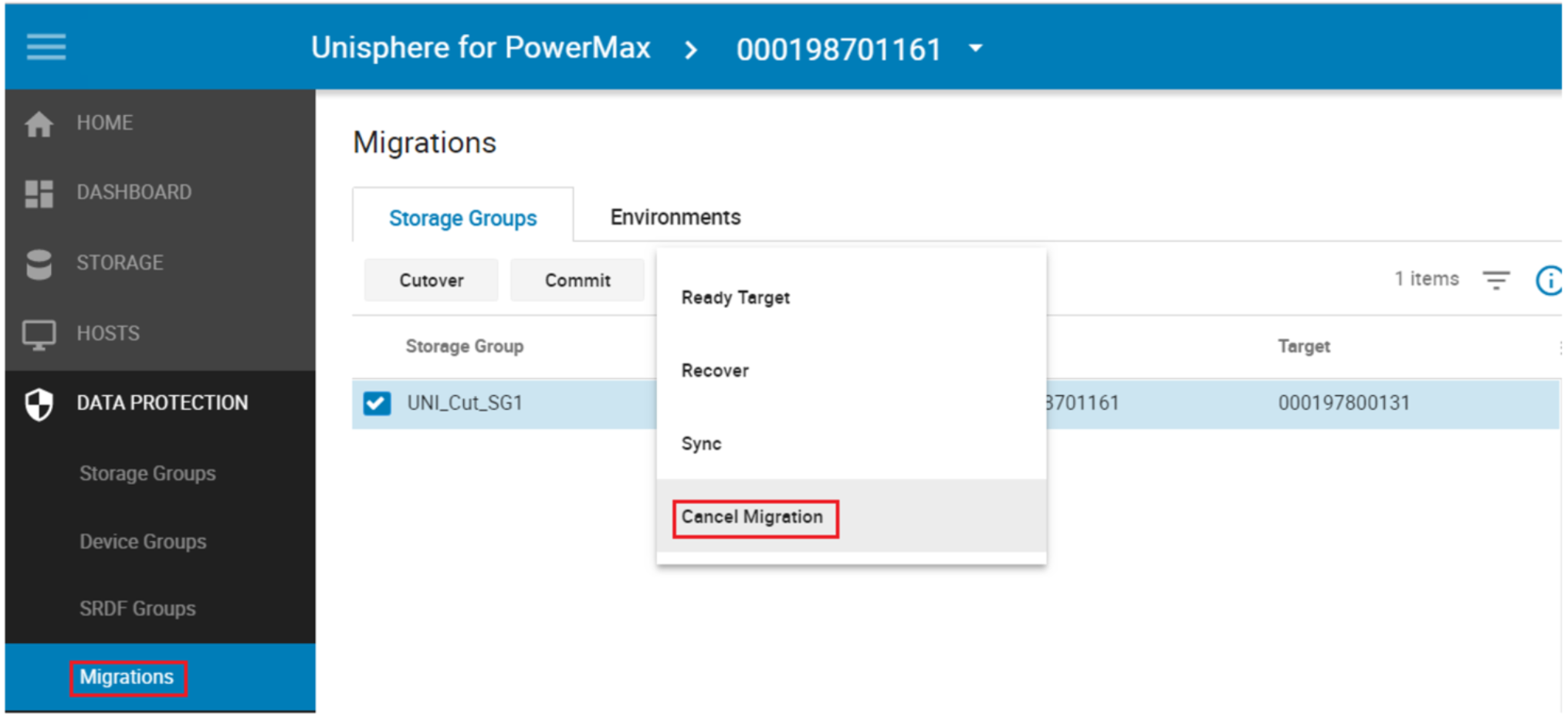
Canceling a migration removes the storage and groups provisioned for the migration on the target array, releases resources allocated by Solutions Enabler to perform the migration, and places the source devices into the state they were in before the Create operation was run. It does not affect the replication pathways put in place with the environment setup.
Note: It is best practice to run a rescan on the host after a Cancel to clear up any dead or invalid paths.
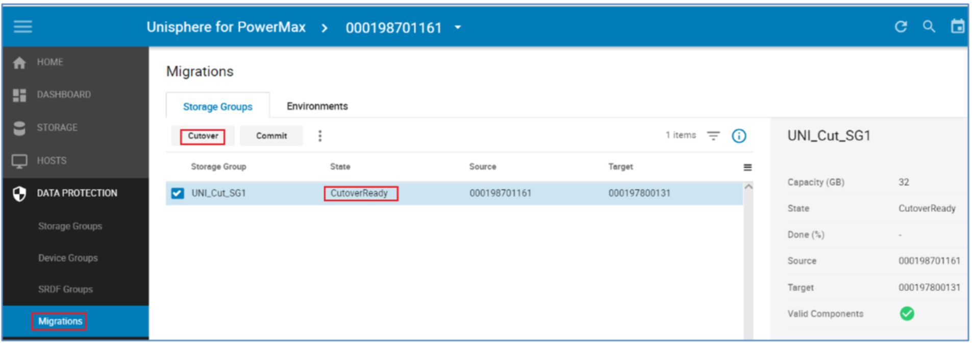
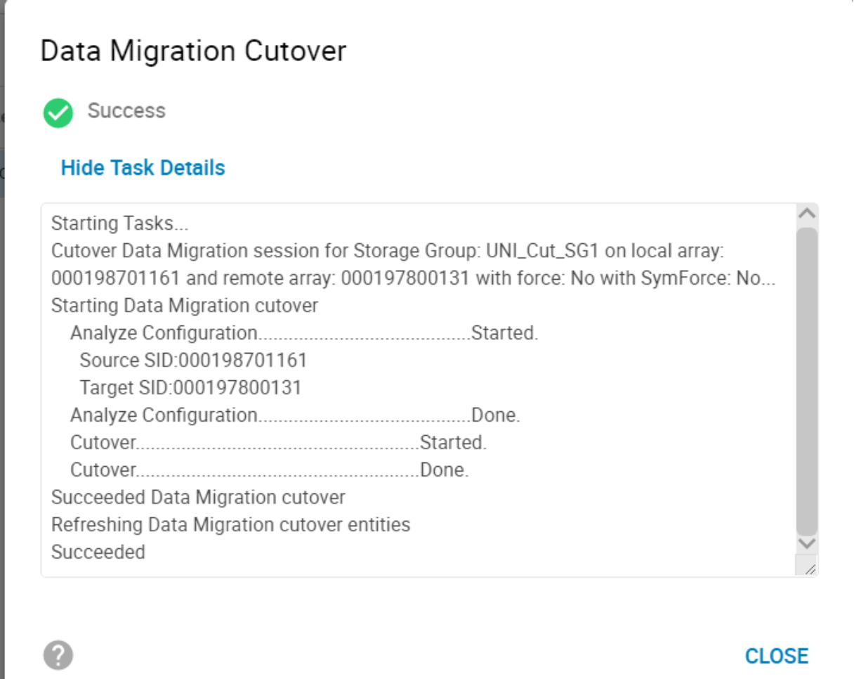
Cutover migration session
Note: A Host rescan that will result in the permanent removal of the now “inactive” paths should not be undertaken post Cutover, this will limit the ability for the migration to be seamlessly canceled and normal operation reverted to the source array. In the case of multiple concurrent NDM sessions sharing the same host the same rule should apply across all sessions when issuing rescans.
The normal operation following a successful Create is a Cutover.
A cutover operation moves the target devices out of pass-through mode, initiates data synchronization from the source to the target and makes the host paths to the source array inactive so that all I/Os are being serviced by the target array. From an SRDF point of view this initiates a full SRDF Restore on the devices.
When the cutover operation completes, the data copy begins. The session is in a Migrating state and will remain in that state until either the pairs are cutover to the new array or other action is taken.
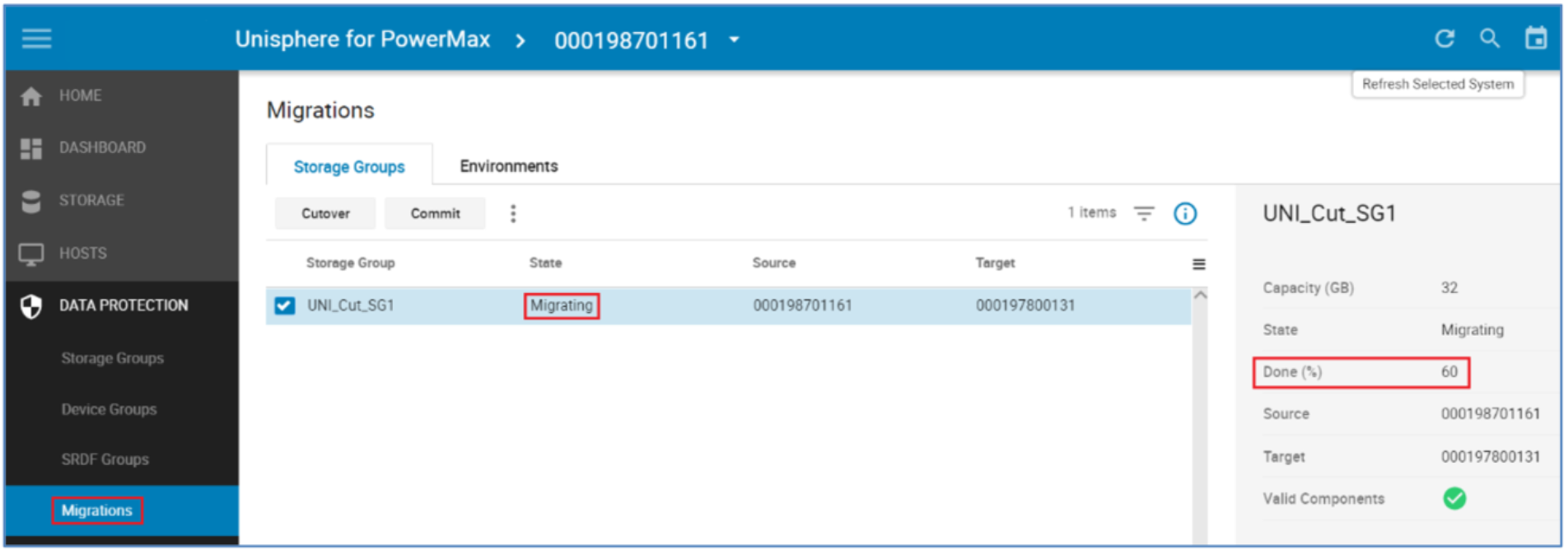
In the example above, the migration session is 60% Copied. Copy time is affected by a number of factors such as:
- How busy the array is overall
- How many RDF paths are part of the NDM environment
- Whether the resources are shared between regular SRDF operations and NDM copies
- Amount of concurrent NDM session ongoing
- Amount of application I/O
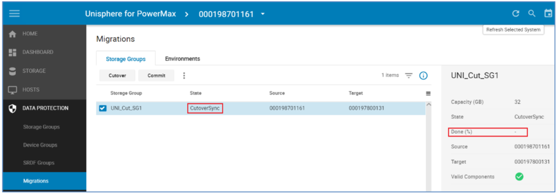
Note: The Done % shows 100% only for a very brief period of time. When the session transitions to a CutoverSync state it is always 100% synchronized.
Examine devices post CutoverSync
The device IDs used on the source and target devices have not changed following the Cutover operation. The target devices are still using the effective WWN of the source devices. The source devices still have the same native and effective IDs.
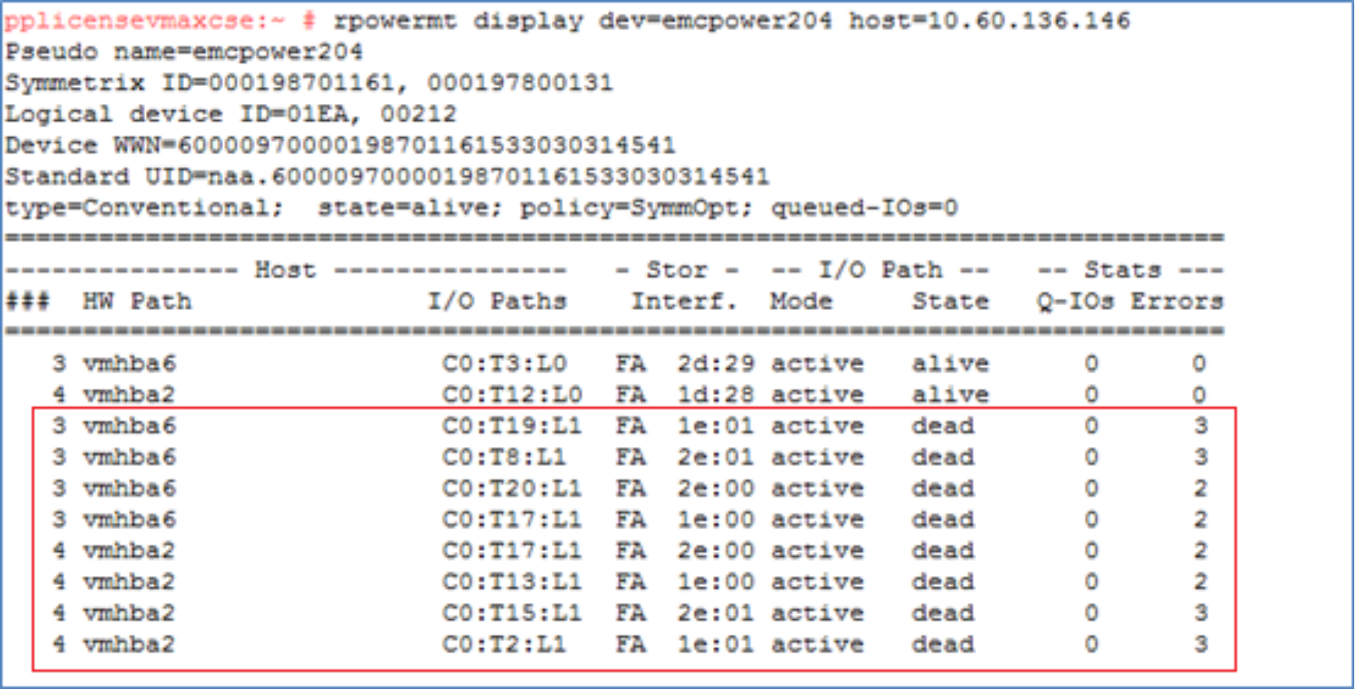
However, the host no longer has access to the source array for I/O processing. All the host I/O is being handled by the target array and is replicating by SRDF/Sync back to the source array. This means that application processing can revert non-disruptively to the source array without data loss or downtime.
Examining the multipathing following the Cutover the paths to the source array have transitioned to a Dead state. The Masking view remains to the source but the paths are in a suspended state so unavailable for host traffic.
Revert to the source array
Because the migration is not permanent until the commit operation is run, after a cutover, the migration can still be canceled and reverted to the source array. To revert back to the source array following a cutover, a cancel is run with the -revert option.
The revert option moves the processing back to the source array and the cancel removes all of the target side entities created for the migration. This operation leaves the environment in the same state as it was prior to the create operation. The revert operation may take some time to run as the system waits for deallocations to complete on the target LUNs before completing. Also, as the revert is running, that the paths to the source array are active again. This is monitored by the VMAX/PowerMax, which waits for the rediscovery before proceeding.
By default, the Revert Flag is selected once the session as reached a Migrating or CutoverSync state.
Perform a host rescan
Following the cancel revert operation, the host paths to the target array are no longer available. The host systems administrator performs a rescan to remove the dead paths to the target array.
Examine the devices post cancel with revert
In this example, the paths to the source array are active once again and the paths to the target array no longer exist.
The SG on the target array has also been removed but the NDM environment remains for any future NDM session between the source and target arrays.
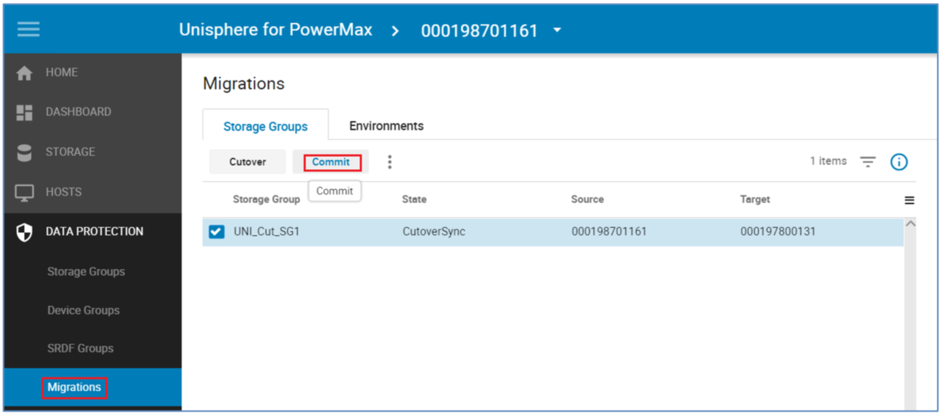
Commit migration session
The normal operation following a successful Cutover is a Commit.
Note: Once the Commit has been run reverting to the Source array will not be possible non-disruptively. This is effectively the point of no return for Source array reversion.
When the data copy is complete, the migration can be committed. The commit operation completes the migration by removing the migrated application resources from the source array and temporary system resources used for the migration. To commit, the state of the migration sessions must be CutoverSync or CutoverNoSync.
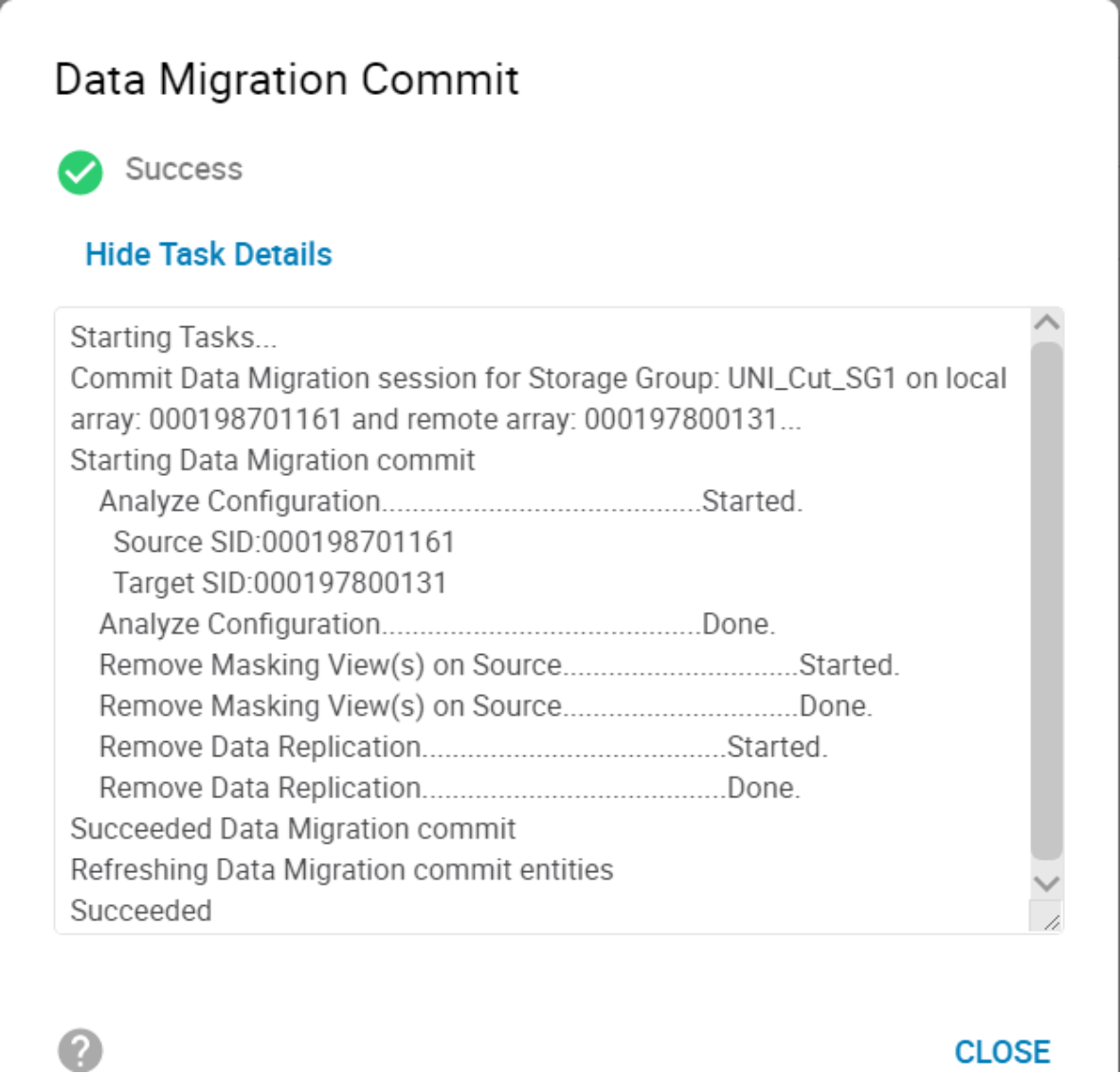
Once the commit is complete, replication between the source and target arrays is terminated. The source devices are no longer be visible to a host because the masking has been removed. The source device IDs have also been permanently swapped with the target device IDs.
Perform a host rescan
After commit operation completes the systems administrator can issue a host rescan to allow the host to clean up the dead paths left by the removed paths to the source array. This host rescan is operating-system specific and also should include a rescan using the host multipathing software if it must be performed separately from the host rescan, as with PowerPath. See Appendix A: Host multipathing software notes for more details on the host multipathing software.
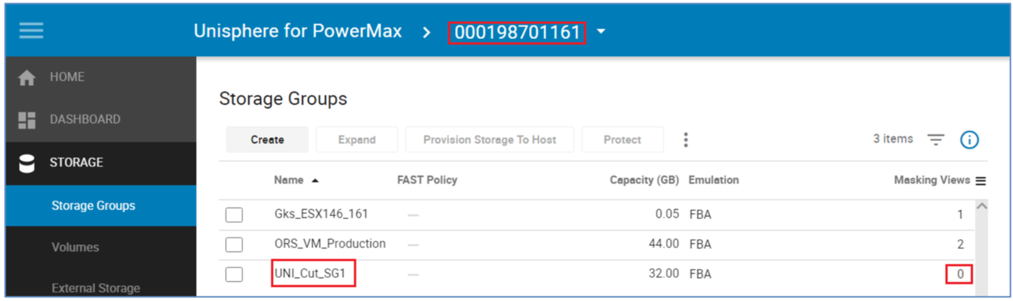
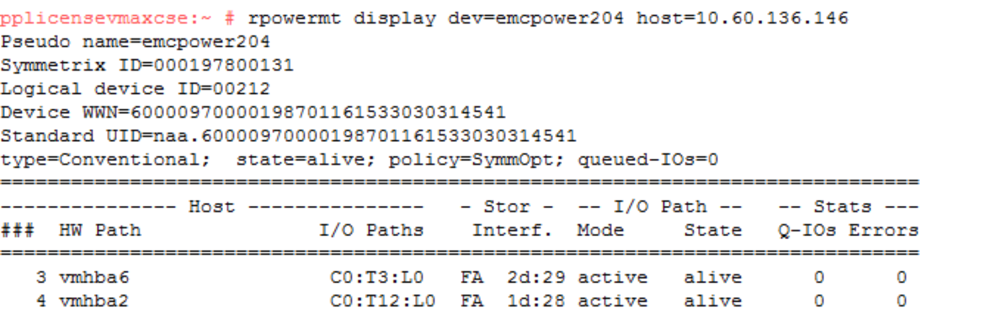
Because the commit completes the migration and removes all of the source side masking, there are no longer any paths seen to the source array. The logical device field only contains the target device and the Symmetrix ID contains the serial number of the target only.
Compare the SGs and LUN WWNs post commit
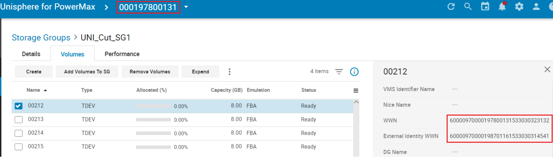
Following the commit operation, each device presents the opposite device ID. The source device now presents the target device ID as its external identity and the target presents the source device ID as its external identity. These changes are permanent and will persist across system power cycles and even the deletion and recreation of the devices. In other words, if device 1EA is deleted, when re-created, it will still show the identity of device 0212.
Therefore, the WWNs have effectively been reverse and the “spoofing” is permanent.
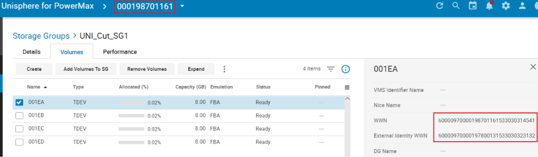
Using device identifiers to track migrated devices
One example of keeping track of devices as they migrate from one array to another is to tag the LUNs. This tagging will persist throughout an NDM session.
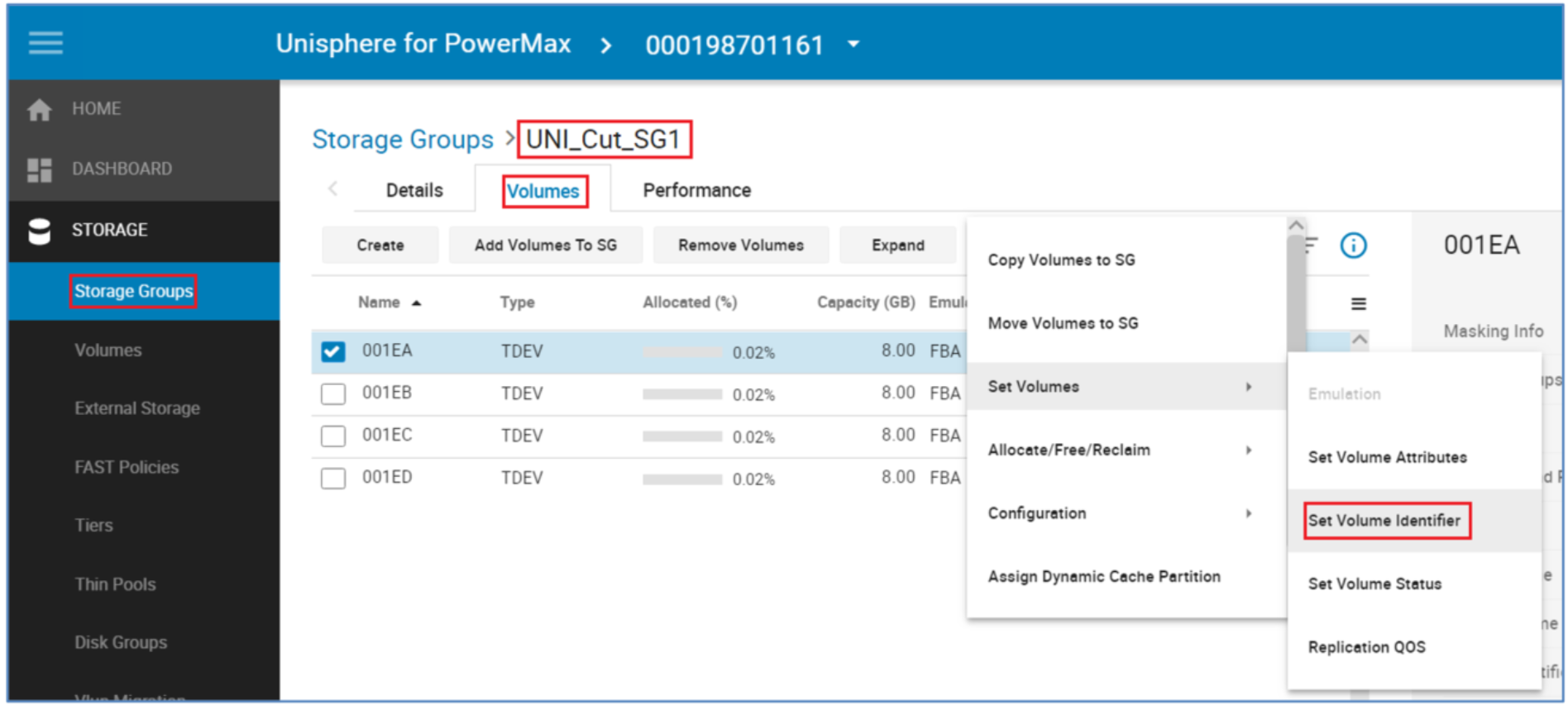
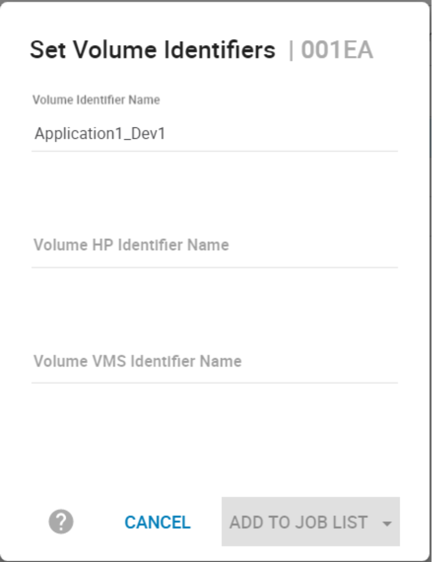
The Tag or Identifier allows a quick reference of a device’s origin or application.
Remove the NDM environment
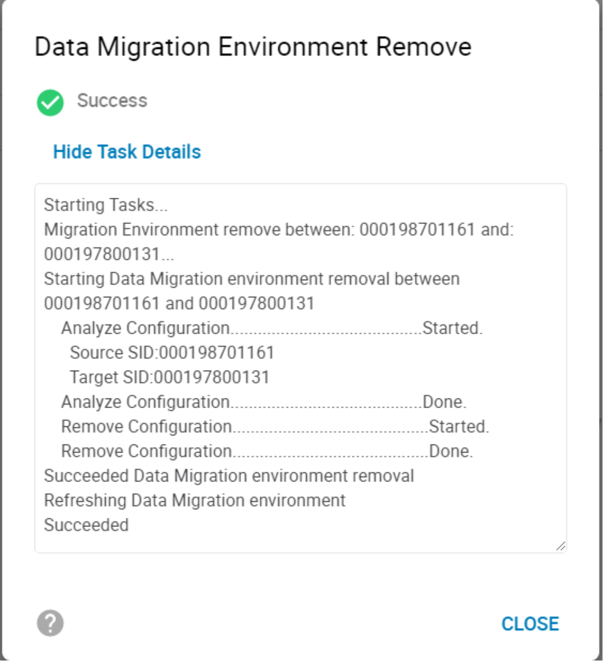
The environment remove operation removes the replication pathway configured by the environment setup operation and removes the resources that were configured to support NDM on the source and target arrays. On successful completion of an environment remove operation, only running an environment setup operation is allowed. An environment removal operation should occur only after all migrations from the source array have been completed.
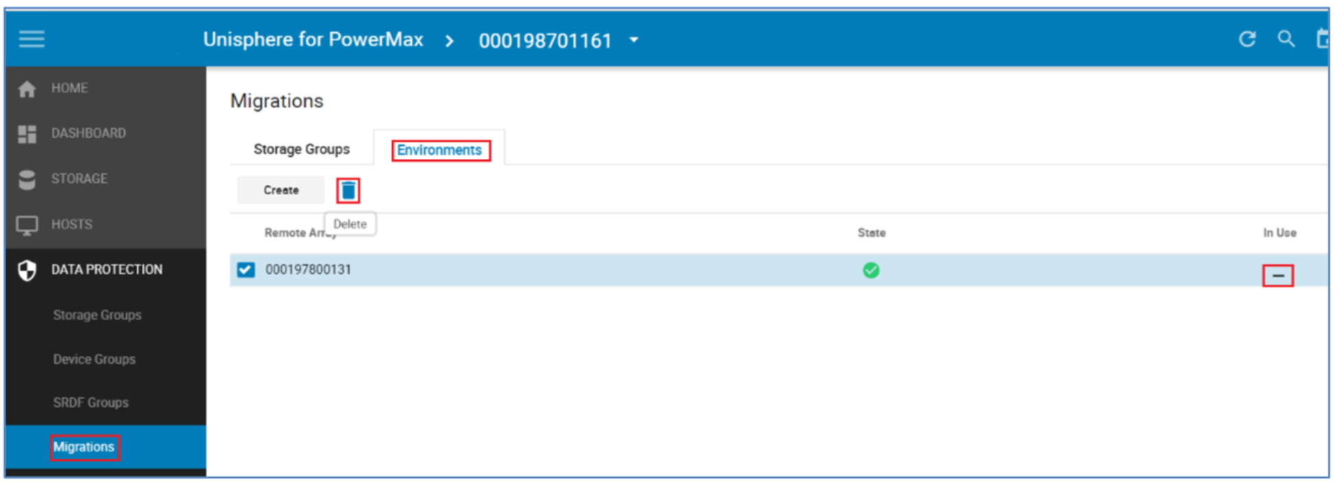
To delete the environment, select the relevant environment from the Environments tab. The In Use symbol identifies if an NDM session is active on this environment.
Once the environment remove operation is complete, the NDM process is complete.
Using Solutions Enabler 9.x
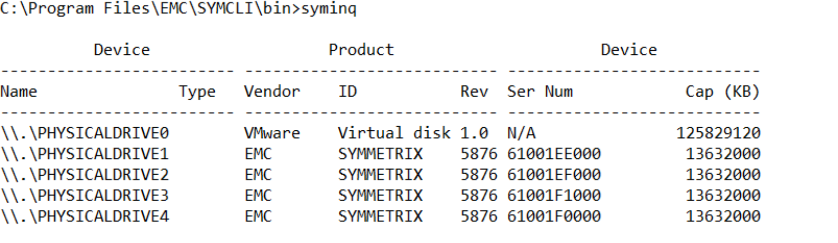
This example shows the migration of five devices (PHYSICALDRIVE0 to PHYSICALDRIVE4) as this syminq display shows.
These devices were previously added as RDMs to the VM with VMware vSphere.
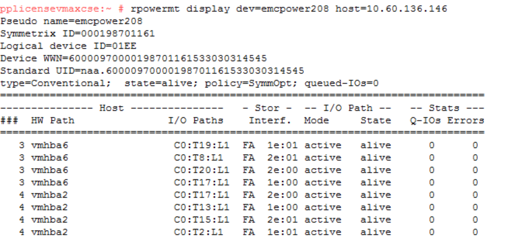
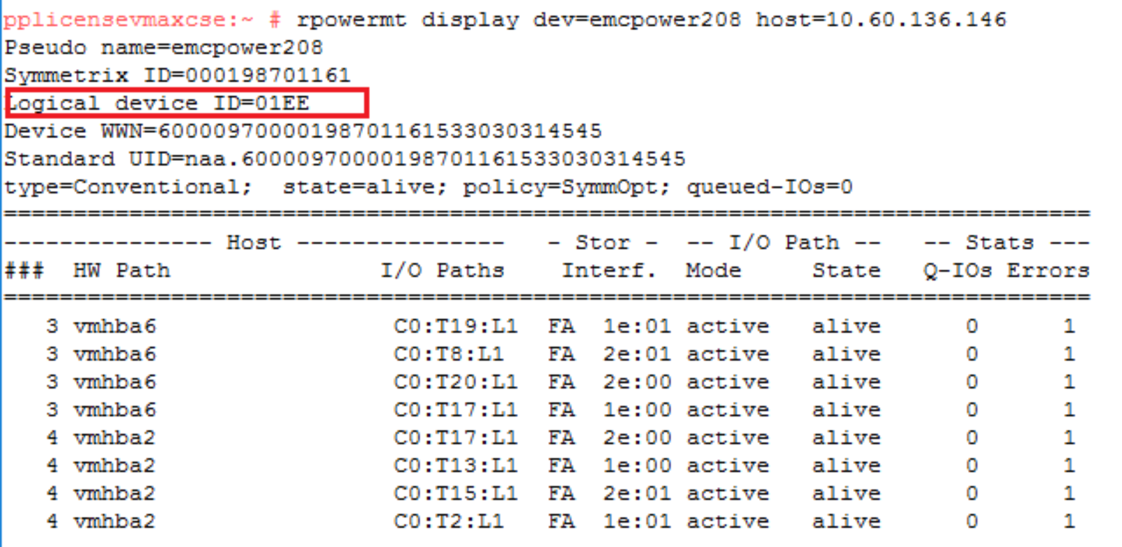
An example of the multipathing setup using device 1EE shows what the pathing looks like prior to the NDM create and the host rescan. For each of the four volumes here there are eight paths to the source array which are all alive and available for host use. At this point, there are no paths to the target array even though our zoning should be in place before the NDM create.
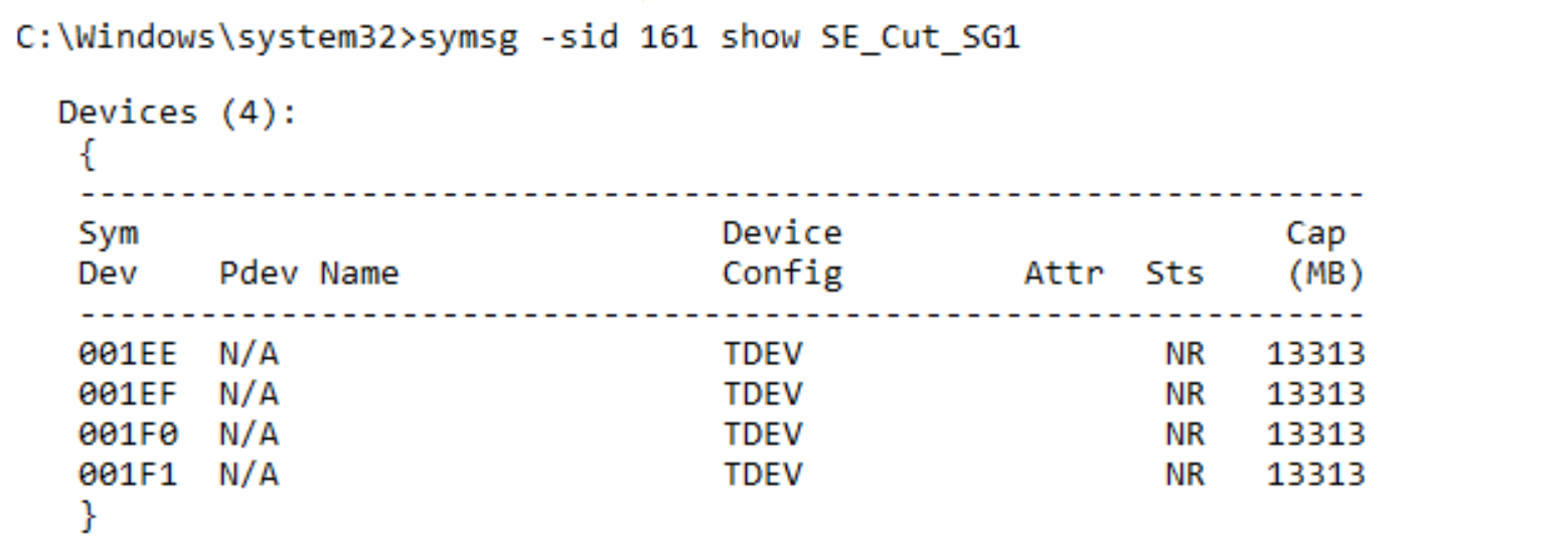
Finally, the Storage Group in which our Application due to be migrated resides consists of four LUNS of 13 GB each, Symm Devices 0x1EE through 0x1F1.
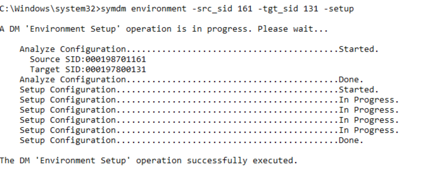
Environment setup
The Environment Setup configures the migration environment that will be required to migrate any application from the source array to the target array. It confirms that both the source and target arrays can support the NDM operations. This includes ensuring that a usable replication pathway for data migration is available between the source and target arrays and creating an SRDF group for the migration.
The setup only must be run once. When the migration pathways and SRDF group are configured, all storage groups on the source array can be migrated until all migrations from the source to the target have been completed.
symdm environment –src_sid <SN of Source> -tgt_sid <SN of target> -setup
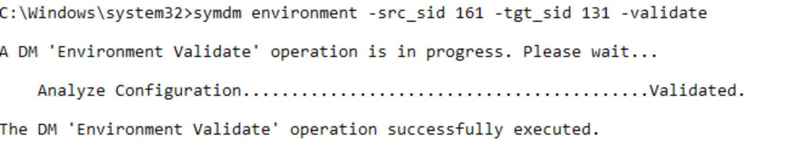
To validate the Environment is working correctly the following can be run at any point.
symdm environment –src_sid <SN of Source> -tgt_sid <SN of target> -validate
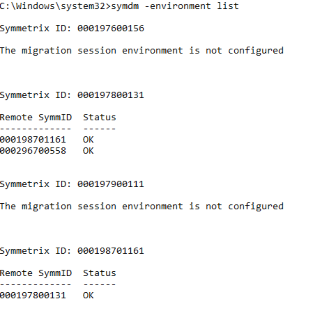
To view all the environments currently configured as well as their status from all available local and remote arrays connected run the following:
symdm –environment list
Once the environment setup is complete, the migration sessions can be created.
Note: NDM Environment setup creates RDF links between the Source and Target using one port per Director for each zoned link. However, post-setup the user can add extra links manually using: symrdf modifygrp –rdfg 250 –add dir xx –remote_dir xx
Create migration and validate migration session
Solutions Enabler examines a specific application’s storage on the source array and automatically provisions equivalent storage on the target array. The target devices are assigned the identity of the source devices and are configured in pass-through mode which allows the data to be accessed through both the source and target devices.
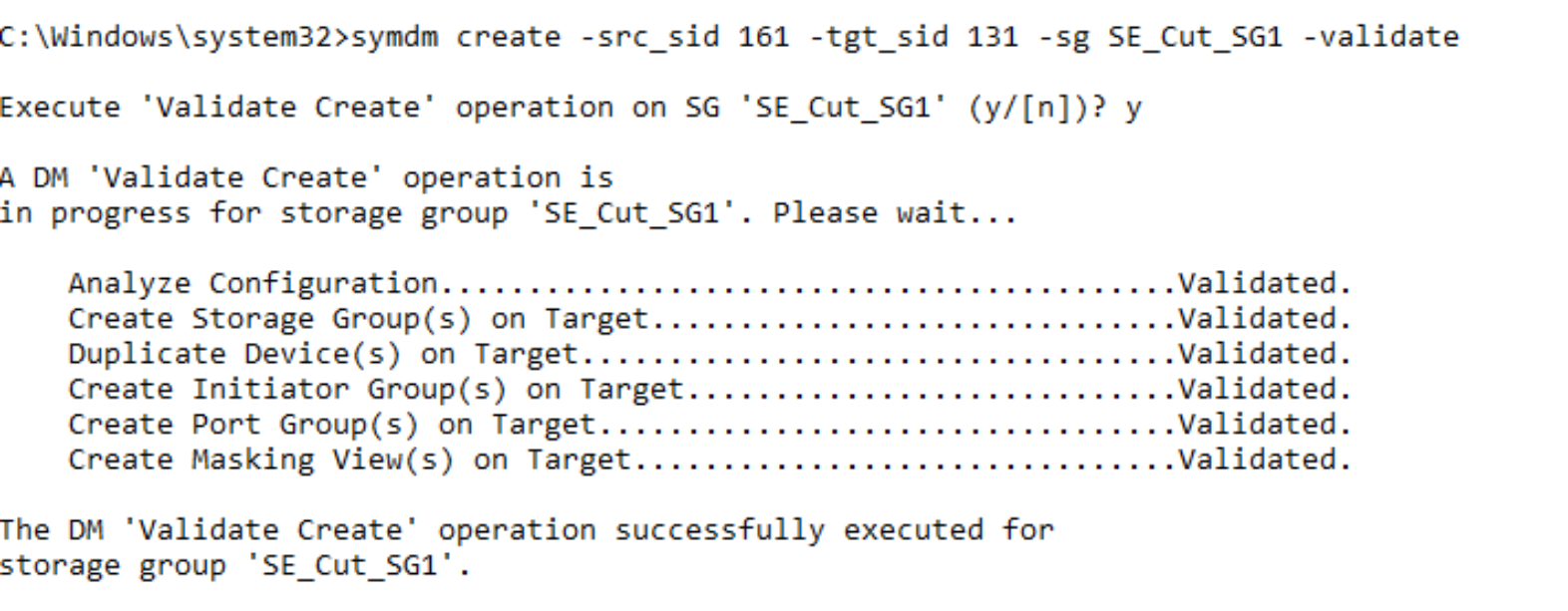
Prior to running the create operation, the target array resources can be validated to ensure that the target array has the resources required to configure the migration sessions and the migration infrastructure exists on both arrays.
symdm create –src_sid <SN of Source> -tgt_sid <SN of target> -sg <SG to be Migrated> -tgt_SRP <Target SRP> -validate
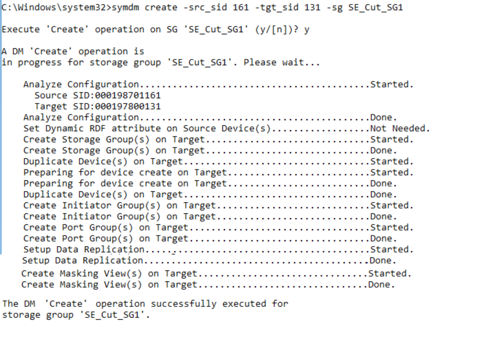
symdm create –src_sid <SN of Source> -tgt_sid <SN of target> -sg <SG to be Migrated> -tgt_srp <target SRP> -tgt_pg <target PG>
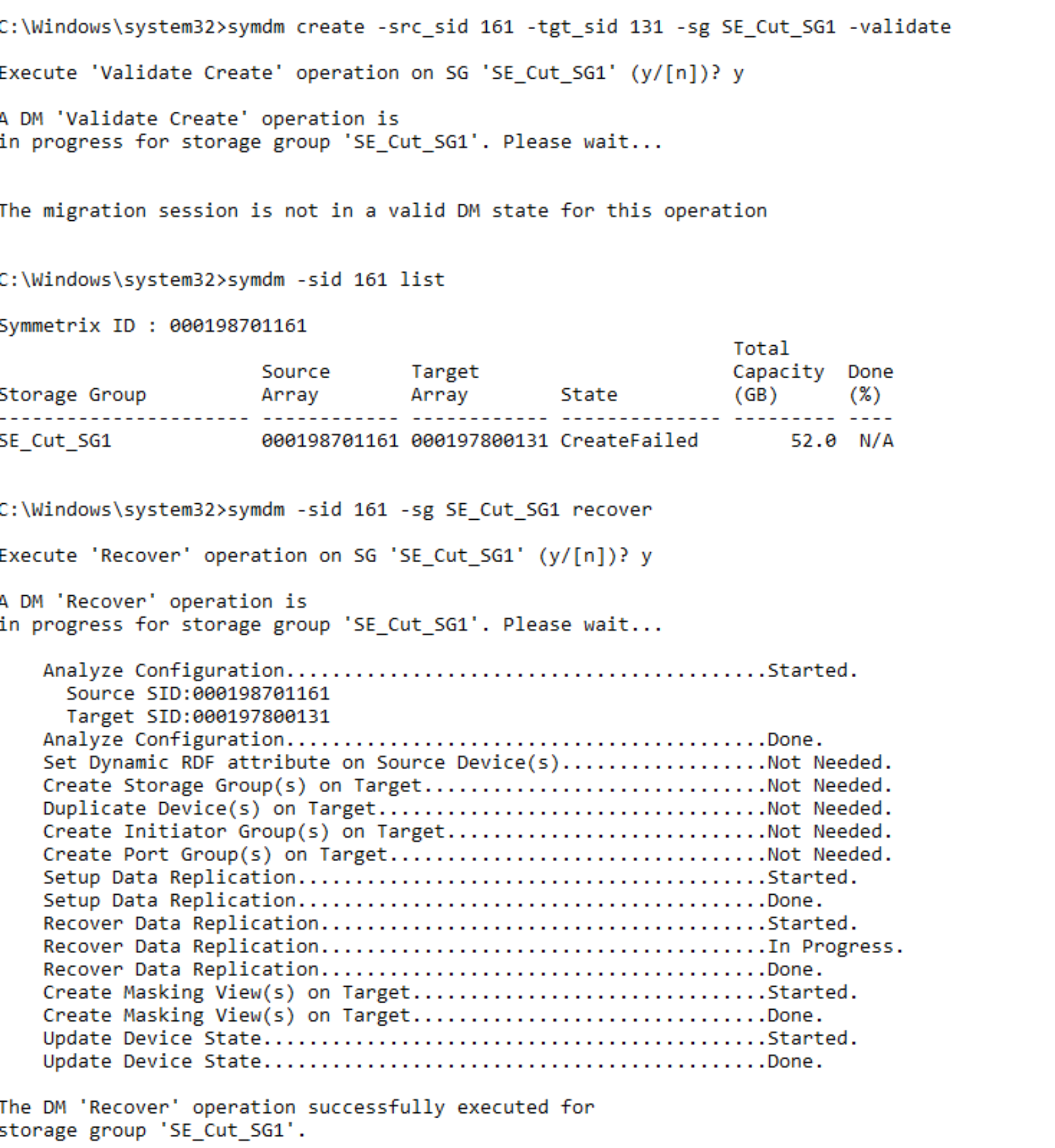
Should the Create command fail for whatever reason (RDF link failure, Target array configuration lock), the session may partially complete some of the elements of the task. The example below shows how the RDF links had an issue just as the links were being established leaving the session in a CREATEFAILED state. The details of the create command show all the elements had been created on the target array such as Port Group, Devices, and the Storage Group.
Using the Recover Command, the NDM process tries to continue from where it left off while verifying all the completed steps are still valid. Should this fail the CANCEL command cleans up all the elements created and returns the array to the state it was before the CREATE was issued.
symdm –sid <SN of Source or Target> –sg <SG to be Migrated> recover
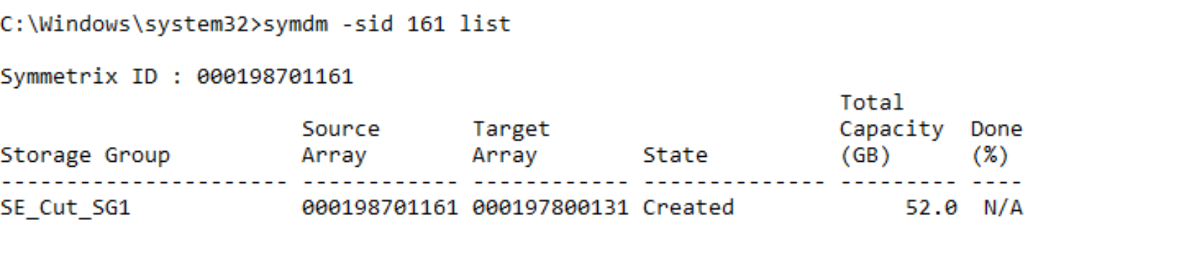
All active NDM sessions can be monitored using the list command, there are variations of this command that give a finer level of detail on the session such as using the –v parameter.
symdm –sid <SN of Source or Target> list
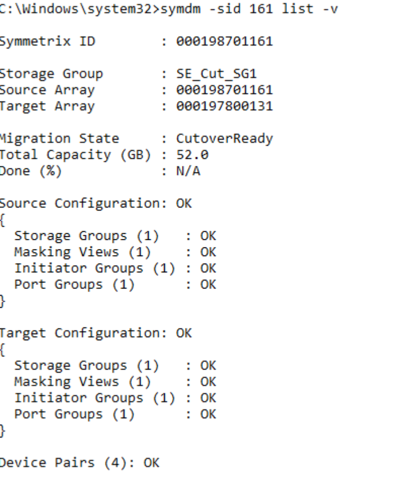
symdm –sid <SN of Source or Target> –sg list –v
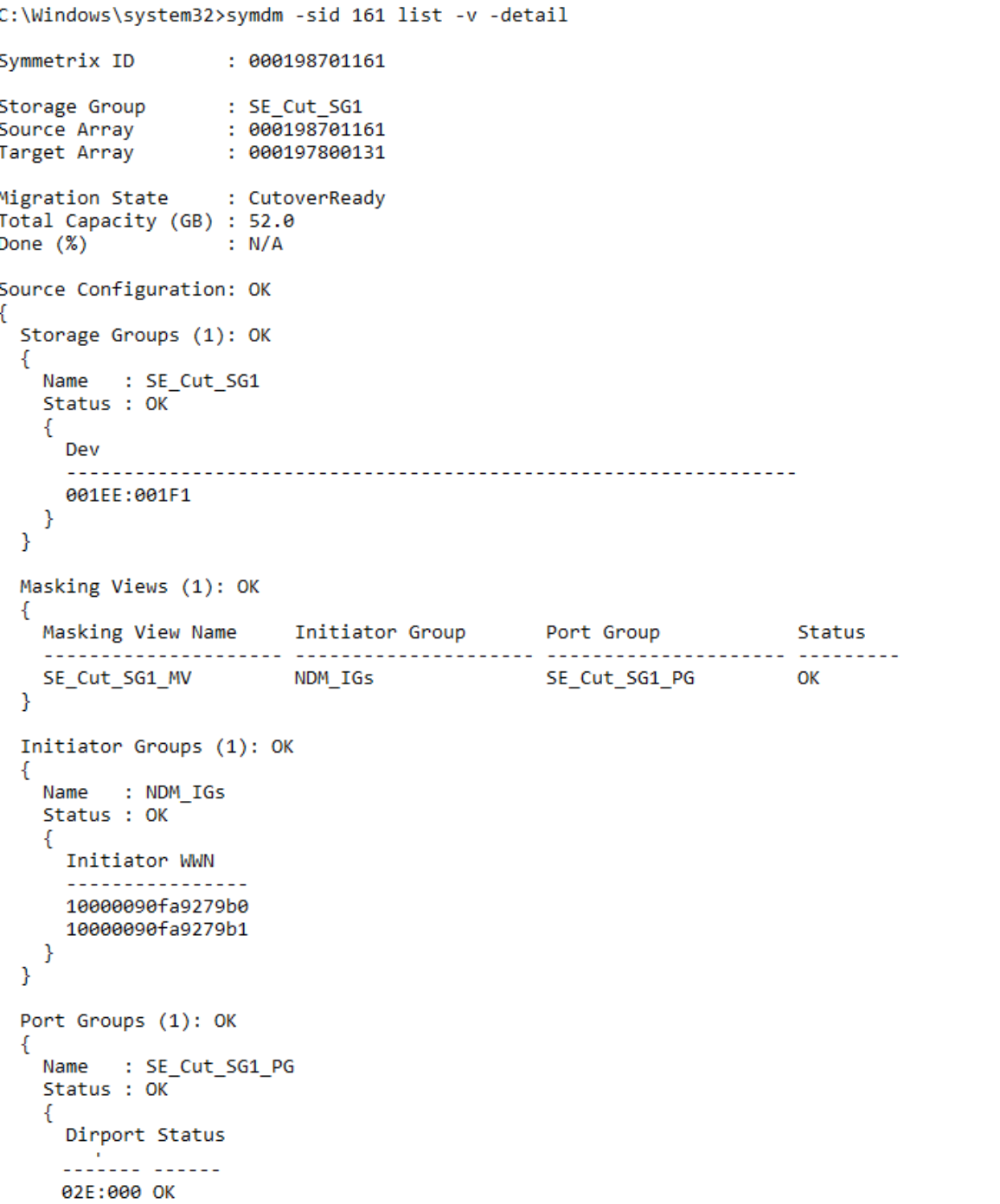
To explore in much finer detail the individual elements of the NDM session use the –v in combination with the –detail parameter. Cropped example:
symdm –sid <SN of Source or Target> –sg list -v -detail
In summary, the Create Command undertakes the following tasks:
- Creates a Storage Group on the Target array (name must not already exist in the target array) with the same name as the Source SG.
- Creates duplicate devices on the target array to match those on the Storage Group.
- Creates an initiator group using Initiators with entries in the login history table.
- Creates a Port group. (if one does not already exist)
- Effective (external) WWNs of the device created on the target are copied from the WWNs of the host devices.
- Creates a masking view to the host from the target array.
Note: During a Cutover NDM migration, the source of the migration is an R2 or an R21 device (if there is existing SRDF DR replication from the source device) and the target is an R1 device. This is different to basic SRDF operations and is required to allow DR protection during a migration using a cascaded SRDF configuration.
Perform a host rescan
Once the Create Command has completed the NDM session is in a Created state.
From this state, we cannot continue to the next step of the process without rescanning the host to pick up the new paths to the target devices.
The systems administrator must issue a host rescan to allow the host to discover the paths to the newly created devices.
Devices go into a CutoverReady state from a Created state after the host rescan is performed and the target devices are discoverable. After this is complete, I/O issued by the application will be directed to either the source or the target arrays through the host multipathing software. This is possible because the target devices are in pass-through mode. Appendix A: Host multipathing software notes has more details on host multipathing software settings.
CutoverReady and pass-through mode
Pass-through mode allows the host to write to or read from either the source or target array. Any write that in sent to the target array is sent across the SRDF link and serviced by the source array. No data is kept on the target array while in a CutoverReady state.
The CutoverReady state is a transitional state. The devices should only be in a CutoverReady state and using pass-through mode for as long as it takes to check that the Create has succeeded properly, to run the host rescan, and to run the Cutover operation.
symdm –sid <SN of Source or Target> list
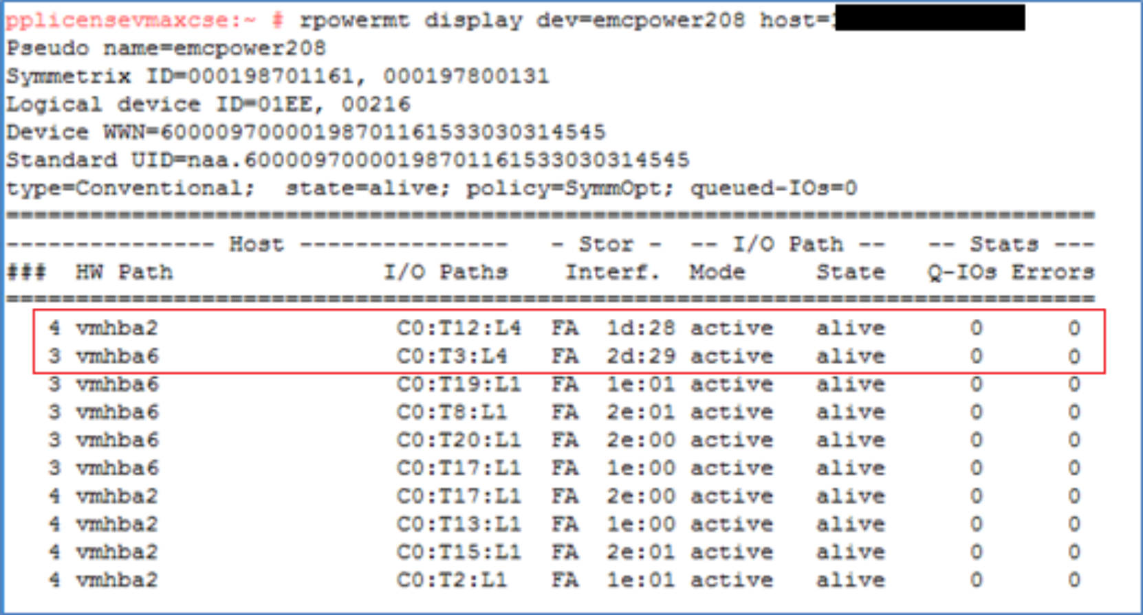
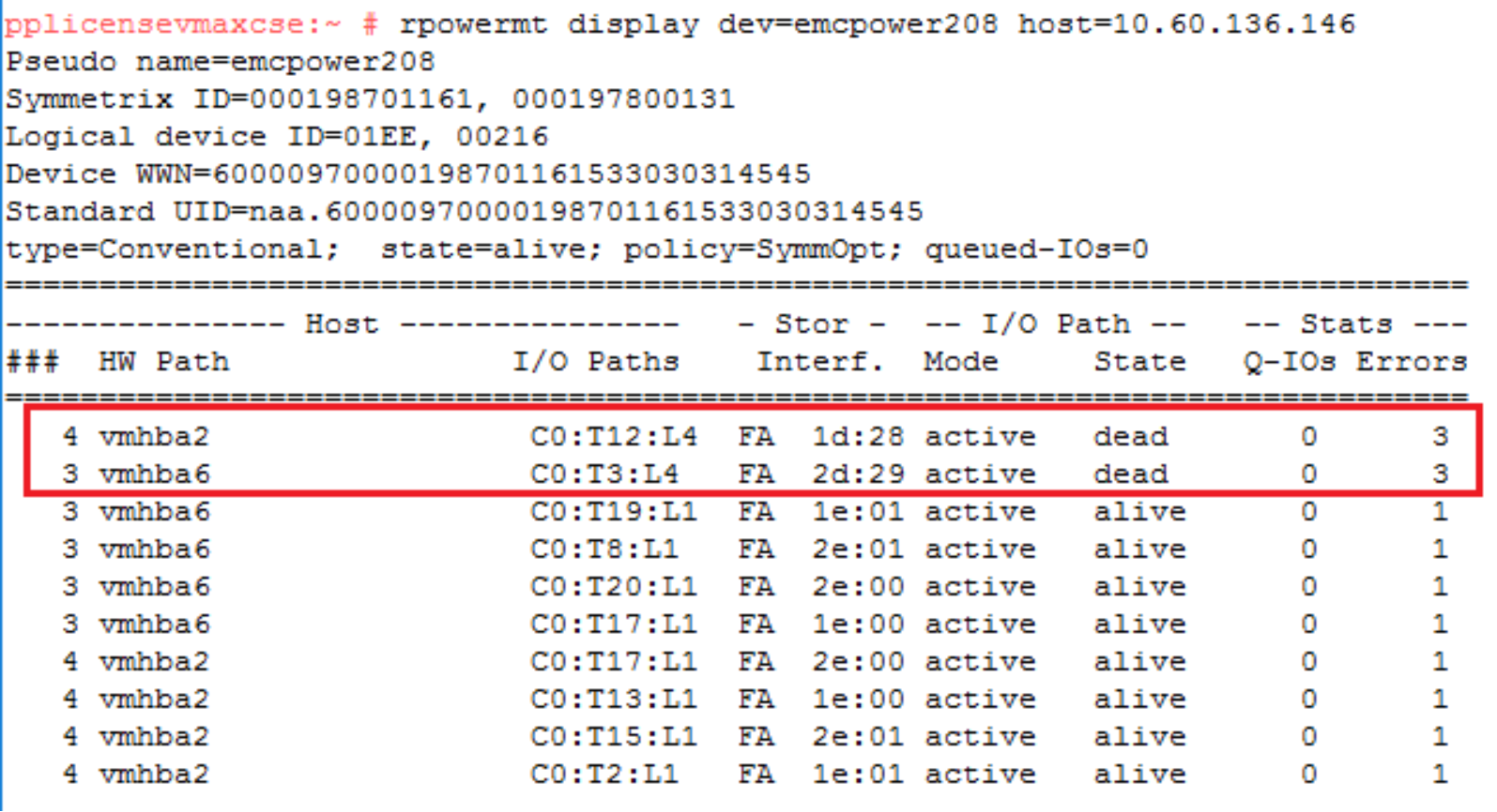
Examining the multipathing software setup there are extra paths online to the target array (in this case two extra paths) after the rescan the number of extra paths is dependent on the zoning setup. It also displays the source and target SIDs and the device numbers involved for these paths. This highlights the fact the WWNs on the LUNs to appear are being spoofed as a single device with just extra paths. Prior to version 6.2 PowerPath was not aware of the NDM process so the dual SIDs and devices IDs were not visible.
Examine the device pairings and the identities following a create
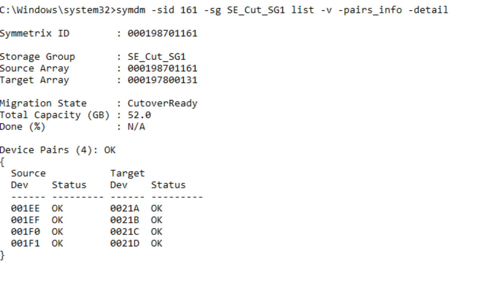
The create operation automatically configures matching volumes on the target array. These volumes are the same size and configuration, though they unlikely to have the same VMAX volume numbers. Following the create operation the four new volumes on the target array are 21A through 21D. Volume 1EE and volume 21A, for example, are paired for NDM operations.
symdm –sid <SN of Source or Target> -sg <SG to be Migrated> list –v –pairs_info –detail
The RDF pairing information can also be seen in the symdev list output.
symdev –sid <SN of Source or Target> list
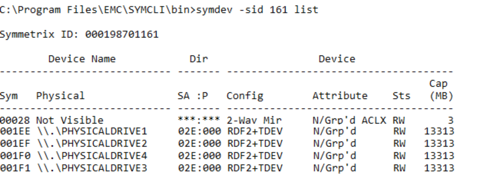
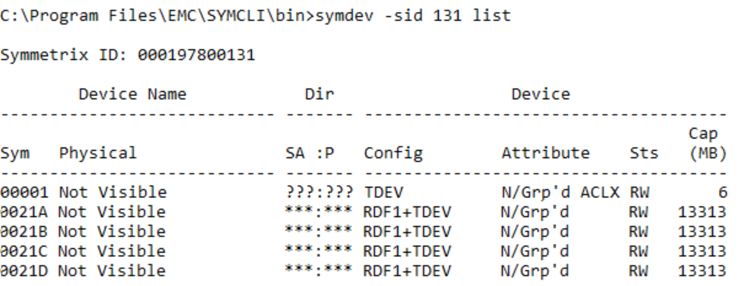
This again highlights the setup from an RDF standpoint with the target devices adopting an RDF R1 personality and the source taking on the identity of an RDF R2.
Note: These personalities vary based on the presence of DR from the source side to a third array in which case the R2 is an R21. The addition of DR to another array from the Target side is possible once the Cutover command has been issued. This changes the personality of the Target devices from a R1 to a R11.
Looking in more detail the effective and native (Internal and External) WWNs of the devices. This shows how “spoofing” these values allows us to manipulate the multipathing software into believing it has just had new paths to the same devices added rather than paths to a completely different array.
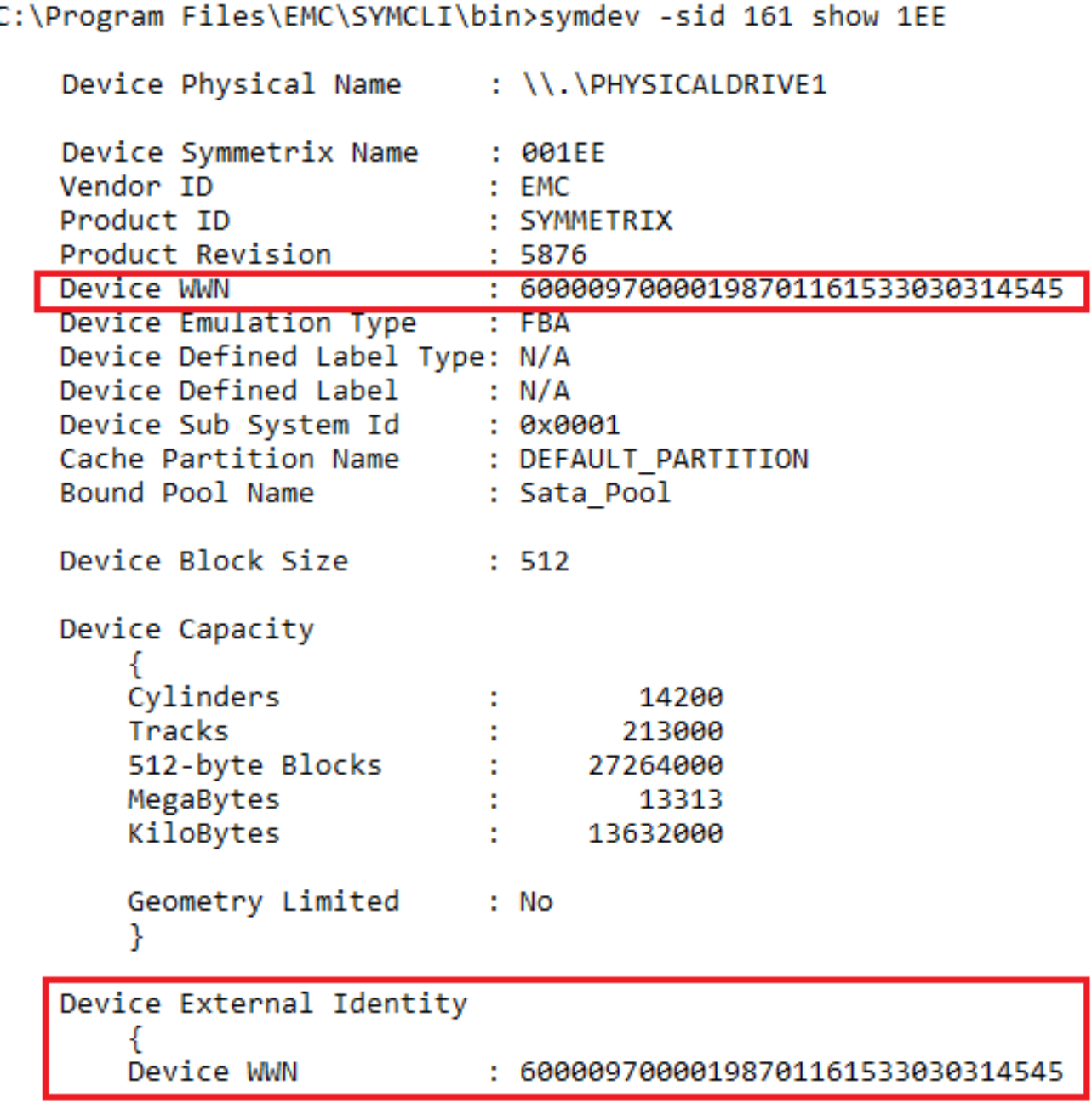
symdev –sid <SN of Source> show <Source Device>
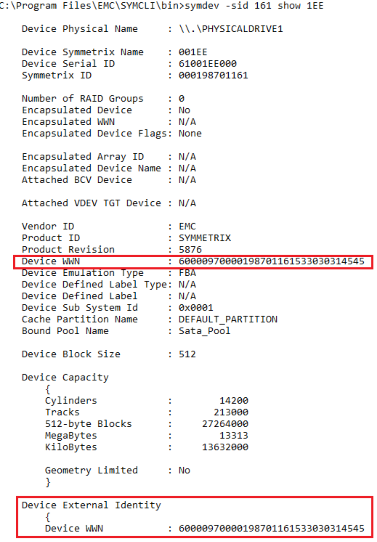
From the example above of a source device we see the Device WWN, the device it was born with, and the external WWN, the WWN presented to the host remains the same at this stage of the process.
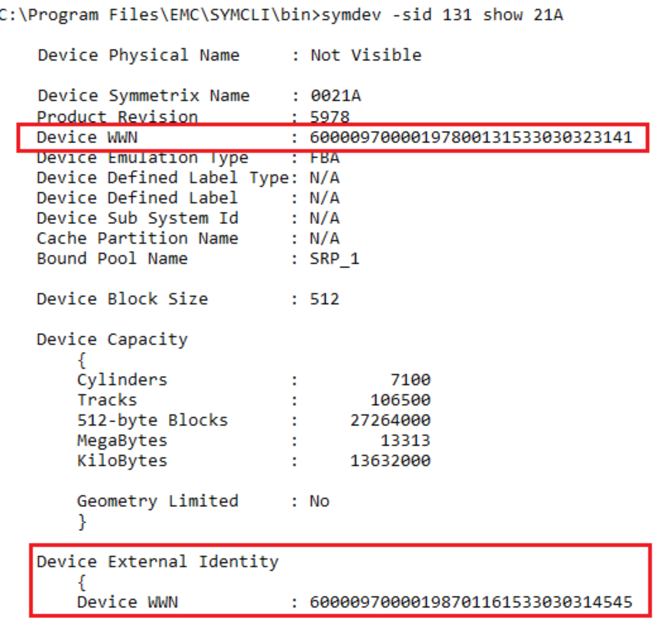
symdev –sid <SN of Target> show <Source Device>
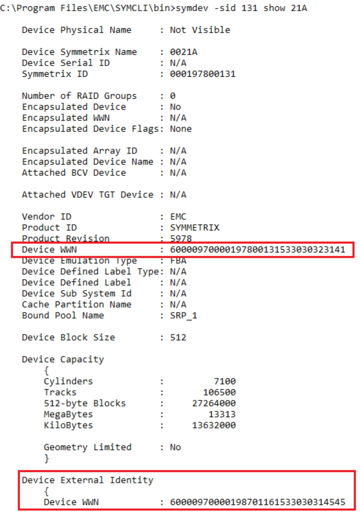
In contrast this example shows the target device. We see the WWN the device was born with and the WWN that it is presenting to the host differs. The device it is presenting to the host is inherited from the Source device thereby appearing as the same device to multipathing software.
Having both device presenting the same WWN means host I/O can use both source and target as its I/O path. However, at this point we are in Pass-Through mode so no data is stored on the target. It is merely passed through over the SRDF link to the source where the I/O is processed as usual.
Note: Due to the extra latency added to I/O that is experiencing the “double hop” if sent down a target path, it is not recommended that the migration session remains in a CutoverReady state for longer than is necessary.
Cancel a migration
At any point before a Commit operation is run on a Storage Group, a migration that has not been committed can be canceled. In this example, the cancel is occurring before the cutover. This operation does not require the –revert flag because processing has not moved to the target array.
symdm –sid <SN of Source or Target> -sg <SG to be Migrated> cancel
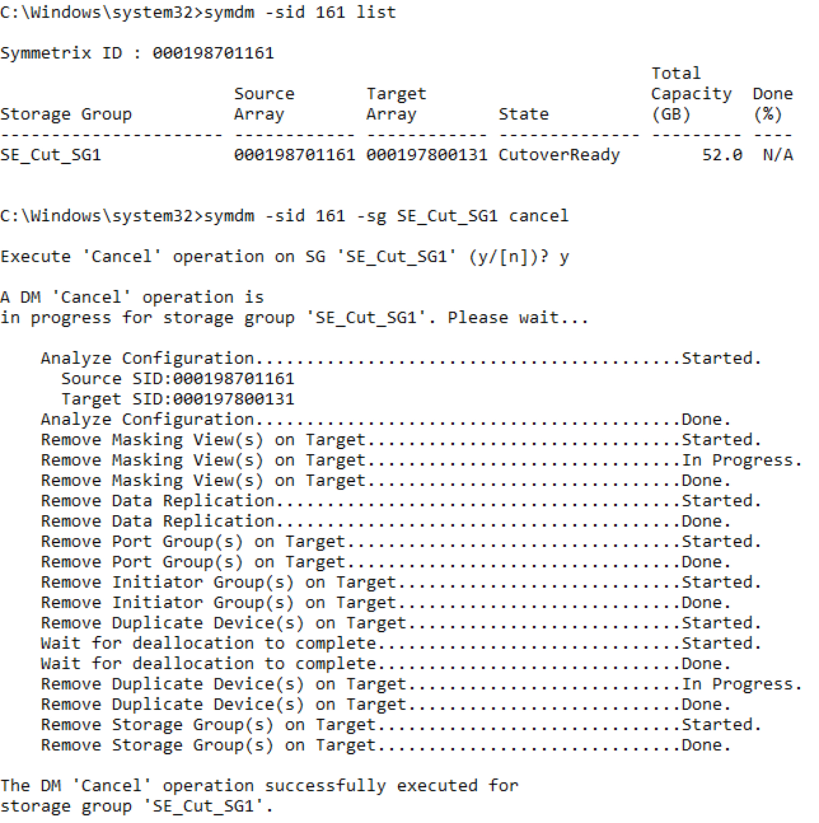
Canceling a migration removes the storage and groups provisioned for the migration on the target array, releases resources allocated by Solutions Enabler to perform the migration, and places the source devices into the state they were in before the Create operation was run. It does not affect the replication pathways put in place with the environment setup.
Note: It is best practice to run a rescan on the host after a Cancel to clear up any dead or invalid paths.
Cutover migration session
Note: A Host rescan that will result in the permanent removal of the now “inactive” paths should not be undertaken post Cutover, this will limit the ability for the migration to be seamlessly canceled and normal operation reverted to the source array. In the case of multiple concurrent NDM sessions sharing the same host the same rule should apply across all sessions when issuing rescans.
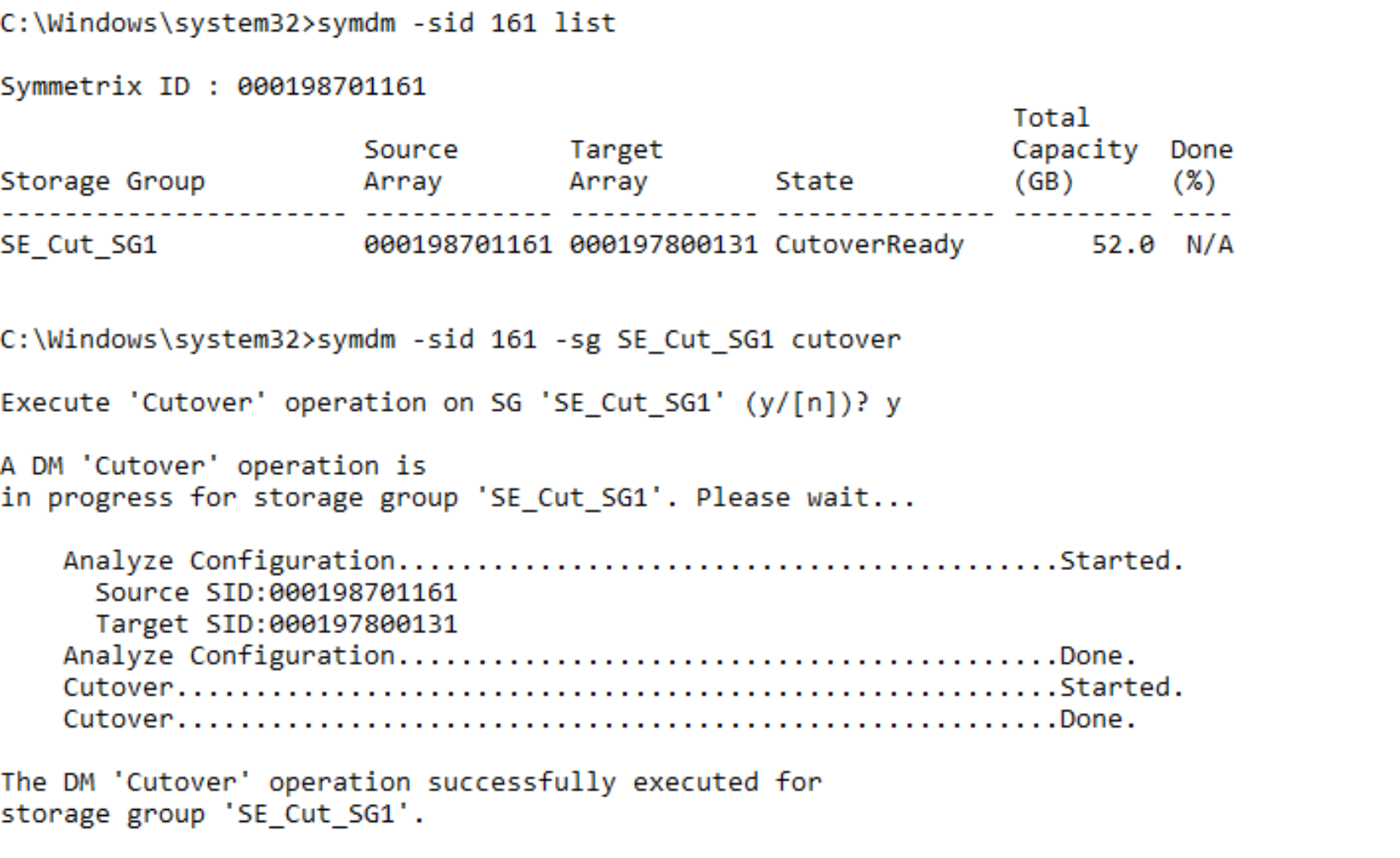
Assuming the previous Cancel was not undertaken, (or having canceled the migration, a new session was created), the host was rescanned and the session reached a CutoverReady state, and the Cutover command can be issued.
A cutover operation:
- Moves the target devices out of pass-through mode.
- Initiates data synchronization from the source to the target.
- Makes the host paths to the source array inactive. The target array is now servicing all I/O requests.
symdm –sid <SN of Source or Target> -sg <Sg to be Migrated> cutover
When the Cutover operation completes, the data copy begins. The session is in a Migrating state and remains in that state until either the pairs are cutover to the new array or other action is taken. The data movement can be monitored using symdm list command. This command has options for displaying Storage Group, Masking View, Initiator Group, Port Group, and device pairs.
symdm –sid <SN of source> list
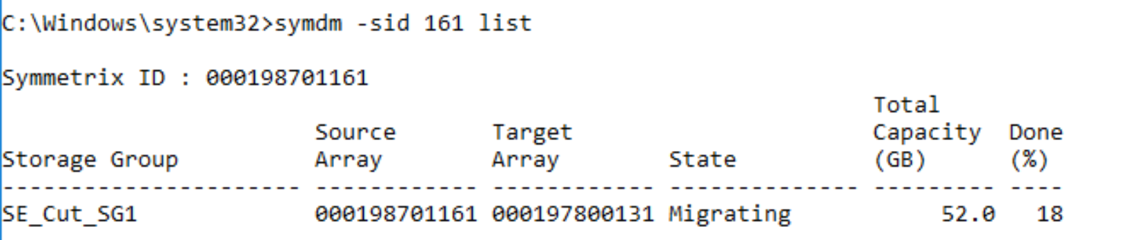
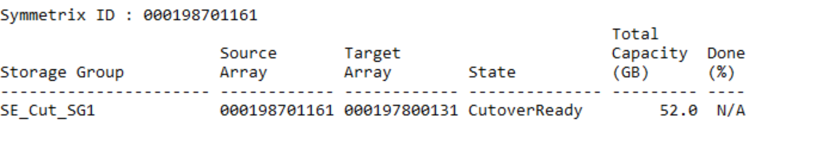
The list command used in this example can be used to see the copy progress to the target array.
In the example above, the migration session is 18% Copied. Copy time is affected by a number of factors such as:
- How busy the array is overall
- How many RDF paths are part of the NDM environment
- If the resources are shared between regular SRDF operations and NDM copies
- Amount of concurrent NDM session ongoing
- Amount of application I/O
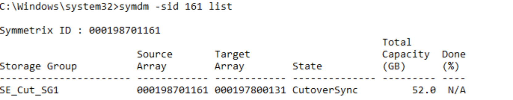
Note: The symdm list command shows 100% done only for a very brief period of time. When the session transitions to a CutoverSync state it is always 100% synchronized.
Examine devices at CutoverSync
The device IDs used on the source and target devices have not changed following the Cutover operation. The target devices are still using the effective WWN of the source devices. The source devices still have the same native and effective IDs.
However, the host no longer has access to the source array for I/O processing. All the Host I/O is being handled by the target array and is replicating using SRDF/s back to the source array. This enables reversion of application processing non-disruptively to the source array without data loss or downtime.
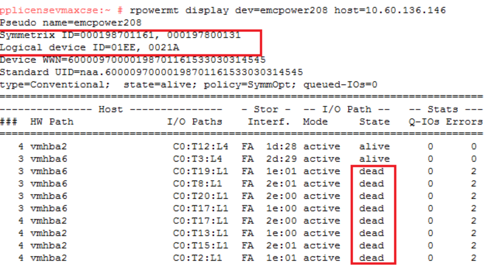
Examining the multipathing following the Cutover, the paths to the source array have transitioned to a Dead state. The Masking view remains to the source but the paths are in a suspended state so unavailable for host traffic.
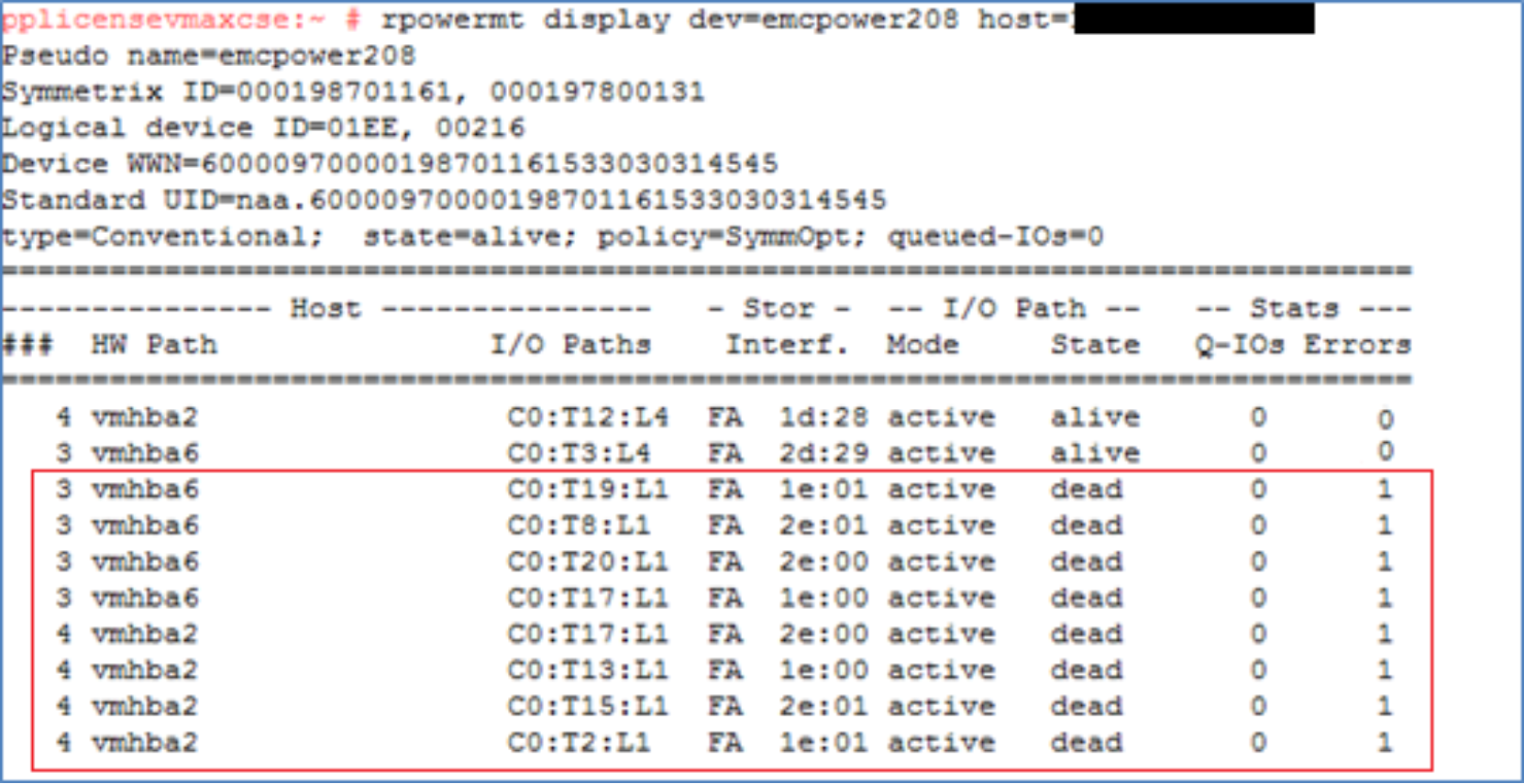
symdev –sid <Source SN> show <Device>
symdev –sid <Target SN> show <Device>
The device IDs used on the source and target devices have not changed following the Cutover operation. The target devices are still using the effective WWN of the source devices. The source devices still have the same native and effective IDs.
Revert to the source array
Because the migration is not permanent until the Commit operation is run, after a Cutover, the migration can still be canceled and reverted to the source array. To revert back to the source array following a Cutover, a Cancel operation is run with the -revert option.
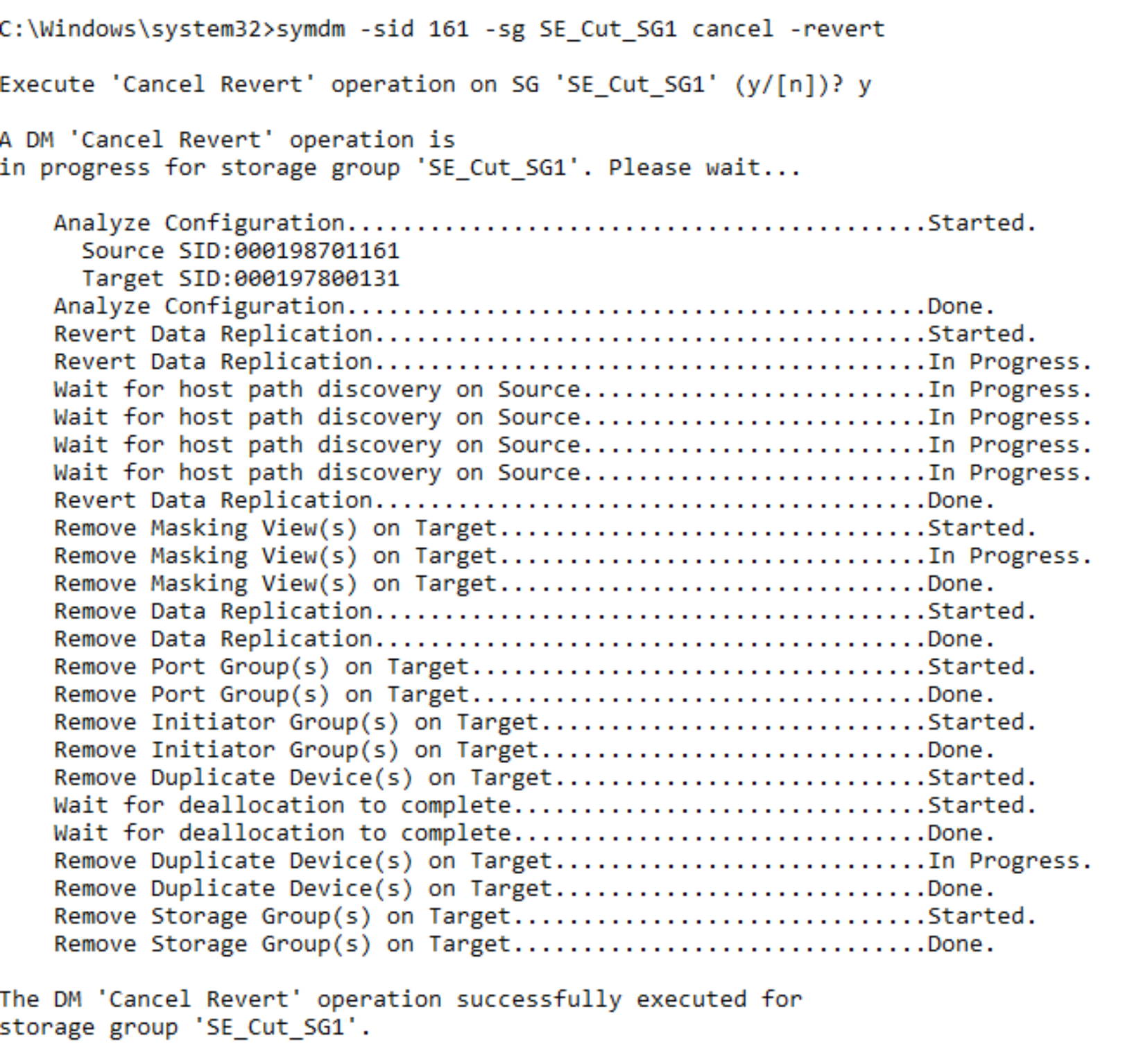
The revert option moves the processing back to the source array and the cancel removes all of the target side entities created for the migration. The operation leaves the environment in the same state as it was prior to the create operation. The revert operation may take some time to run as the system waits for deallocations to complete on the target devices before completing. Also, as the revert is running, the paths to the source array become active again. This is monitored by the source and target, which waits for the rediscovery before proceeding.
symdm –sid <Source or Target SN> -sg <Migration SG> cancel -revert
Perform a host rescan and examine the devices
Following the Cancel operation with the Revert option, the host paths to the target array are no longer available. The host systems administrator runs a rescan to remove the dead paths to the target array.
The identity of the target array has been completely removed from the PowerPath device following the rescan. Before that the identity remained and the paths were showing as dead.
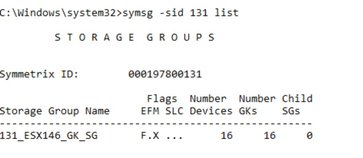
The SG on the target array has also been removed but the NDM environment remains for any future NDM session between the source and target arrays.
symsg –sid <SN of Target> list
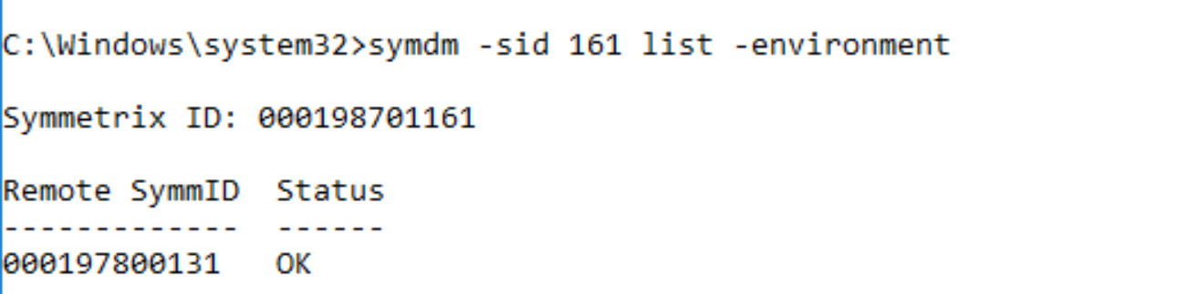
symdm –sid <SN of Source or Target> list –environment
Commit migration session
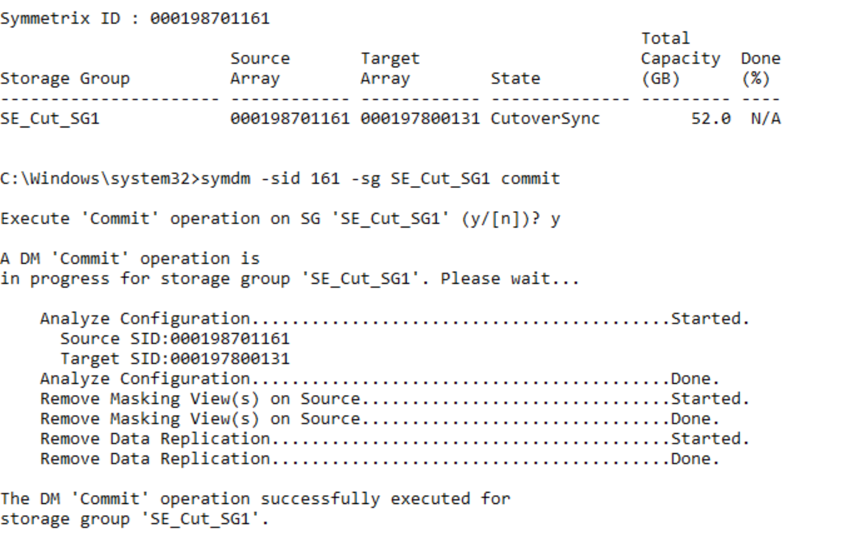
When the data copy is complete, the migration can be committed. The Commit operation completes the migration by removing the migrated application resources from the source array and temporary system resources used for the migration. The Commit operation requires that the state of the migration session is CutoverSync or CutoverNoSync.
Note: Once the Commit has completed, reverting to the Source array will not be possible non-disruptively. symdm –sid <SN of Source or Target> -sg <SG to be migrated> commit
symdm –sid <SN of Source or Target> -sg <SG to be Migrated> commit
Once the Commit operation is complete, replication between the source and target array ends. The source devices are no longer be visible to a host because the masking has been removed. The source device IDs have also been permanently swapped with the target device IDs.
Perform a host rescan
After the commit operation completes, the systems administrator runs a host rescan so that the host can clean up the dead paths left by the removed paths to the source array. This host rescan is OS-specific and also should include a rescan using the host multipathing software. See Appendix A: Host multipathing software notes for more details on the host multipathing software.
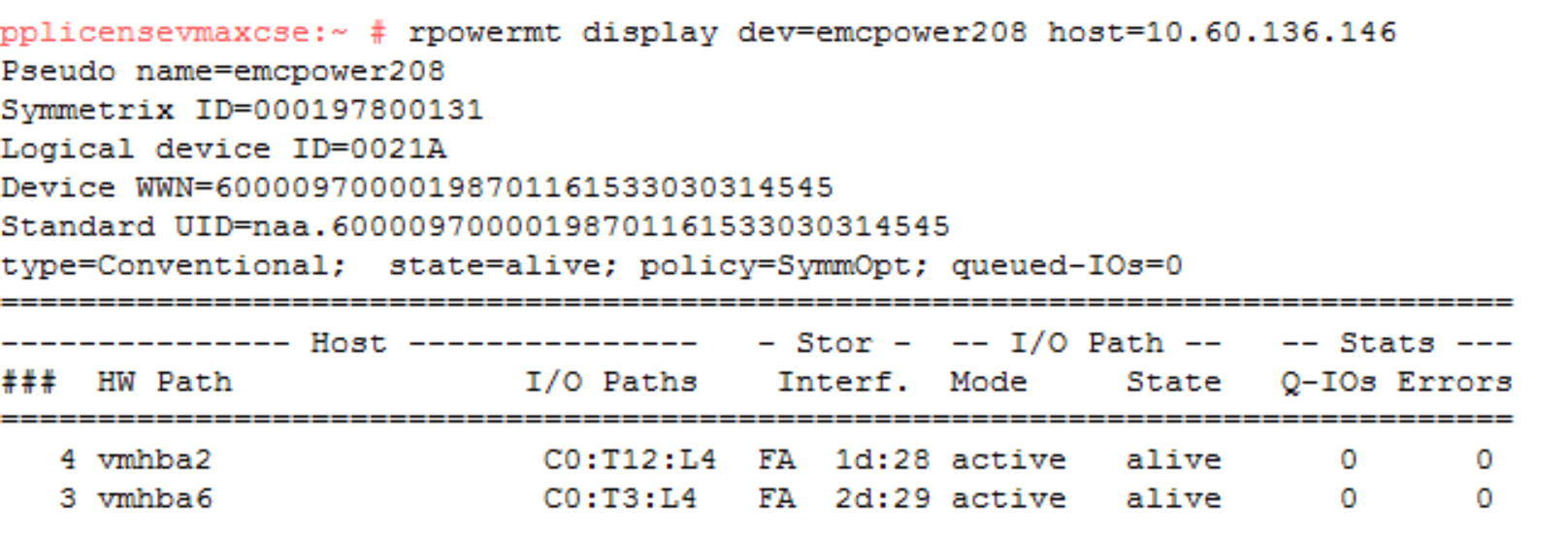
The commit operation completes the migration and removes all of the source side masking. Therefore, there are no longer any paths seen to the source array.
The following shows the pre-rescan status:
The post-rescan status is displayed as follows:
Compare the SGs and LUN WWNs post commit
Following the Commit operation, each device presents the opposite device ID. The source device now presents the target device ID as its external identity and the target presents the source device ID as its external identity. These changes are permanent and will persist across system power cycles and even the deletion and recreation of the devices. In other words, if device 1EE is deleted and then re-created, it still retains the identity of device 021A.
Therefore, the WWNs have effectively been reversed and the spoofing is permanent.
symdev –sid <SN of Source> show <Device to be Migrated>
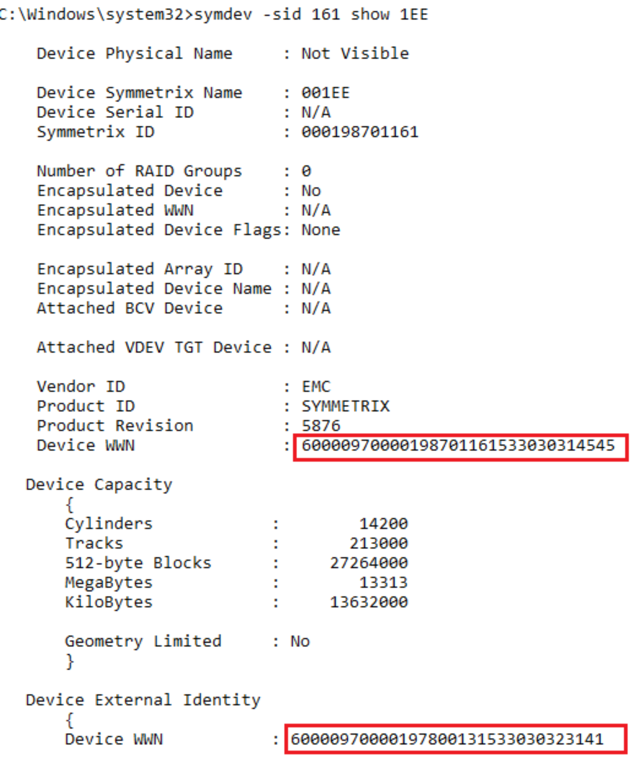
The example shows that the Source device has inherited the WWN of the target device. This is the device WWN that it will display to a host should it be masked. This allows the customer to reuse the array and the devices previously migrated without the risk of data loss in the case where the same devices were masked into the SAN of the target devices.
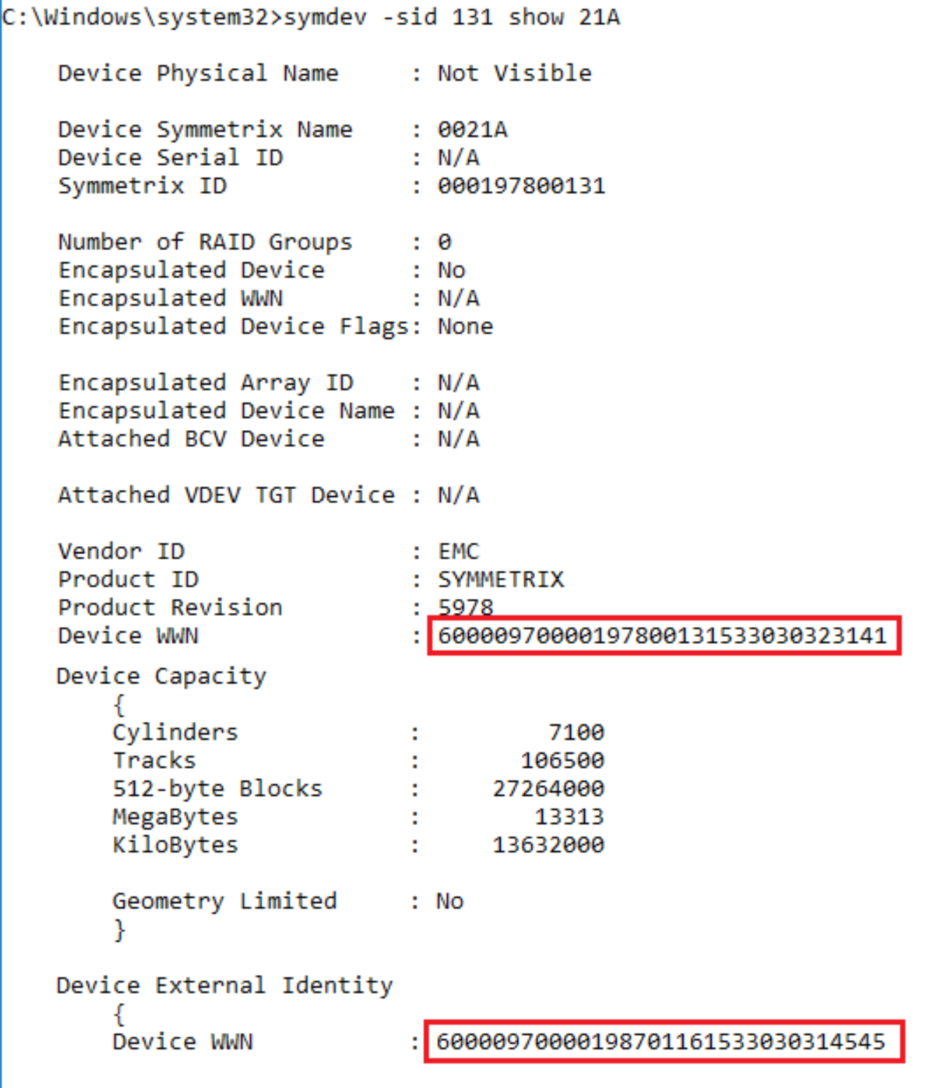
On the target device, the device retains the external WWN from the source array that it inherited during the create step. This remains the WWN after the completion of the migration.
Note: The native identities of devices can be displayed using the –native option on the syminq command.
Remove the NDM environment
The environment remove operation removes the replication pathway configured by the environment setup operation, and it removes the resources that were configured to support NDM on the source and target arrays. On successful completion of an environment remove operation, only running an environment setup operation is allowed. An environment removal operation should occur only after all migrations from the source array have been completed.
symdm –src_sid <SN of Source> -tgt_sid <SN of Target> environment –remove
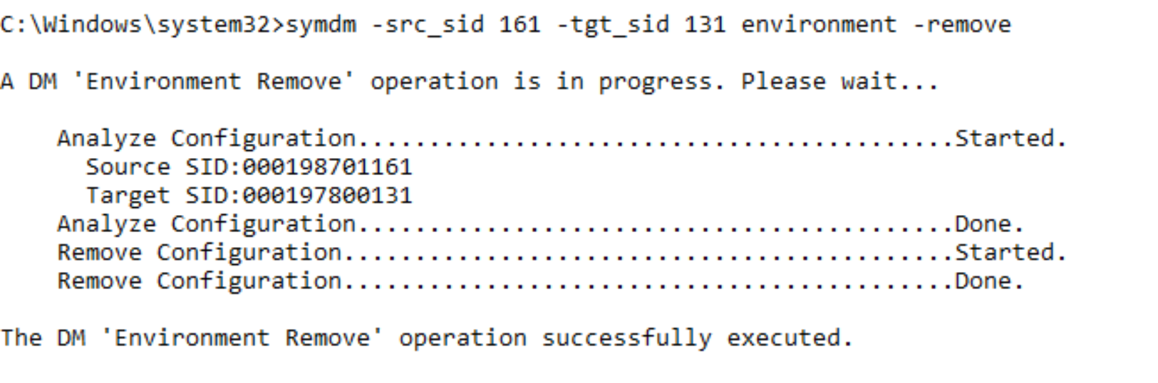
Once the environment remove operation is complete, the NDM process is complete.