
None
None
-
The following diagram shows the network architecture that is configured on both the sites.
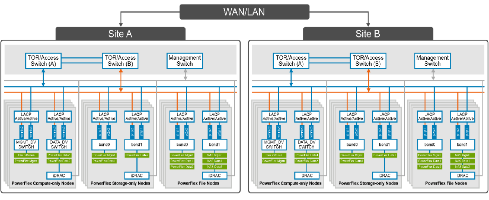
Figure 6. Network design for PowerFlex file replication using StorageMAP
At the physical layer, two Top of Rack (TOR) switches are used for redundancy and load-balancing purposes at each site. A peer link is configured on both the TOR switches.
The network ports of different network interfaces on each PowerFlex node are configured to carry PowerFlex management, PowerFlex data and PowerFlex file traffic. An LACP bond is configured at the host level with two network interfaces to form a single-bonded (logical) interface for increased bandwidth and redundancy.
The bond0 and bond1 are the LACP bonded interfaces and are configured with multiple VLAN tagged interfaces for all the PowerFlex networks. The traffic is logically separated by creating VLANs which separate different traffic on the bond interfaces as shown in the preceding figure. PowerFlex data1 and data2 are used for data traffic whereas NAS_data1 and NAS_data2 are dedicated for PowerFlex File data traffic.
The following table shows the different networks that are configured for this solution. For more information, see the PowerFlex node VLAN setup.
Table 2. Network details
Network type
VLAN ID
OS Management
105
PowerFlex Management
150
PowerFlex Data 1
151
PowerFlex Data 2
152
NAS Management
250
NAS Data 1
251
NAS Data 2
252
Note: Based on the physical locations of Site-A and Site-B, it is recommended to enable (TOR-link) connectivity between the two sites for replication.