
None
None
-
The following image shows the logical architecture of the PowerFlex file clusters using two-layer deployment architecture.
In this example, on each site there are four nodes that are dedicated for storage. PowerFlex storage (SDS) components are installed on these four nodes, two nodes that are configured as PowerFlex file nodes and three more client nodes that are dedicated for running client applications consuming the file shares. This model decouples compute from storage, allowing either of them to scale independently, as needed.
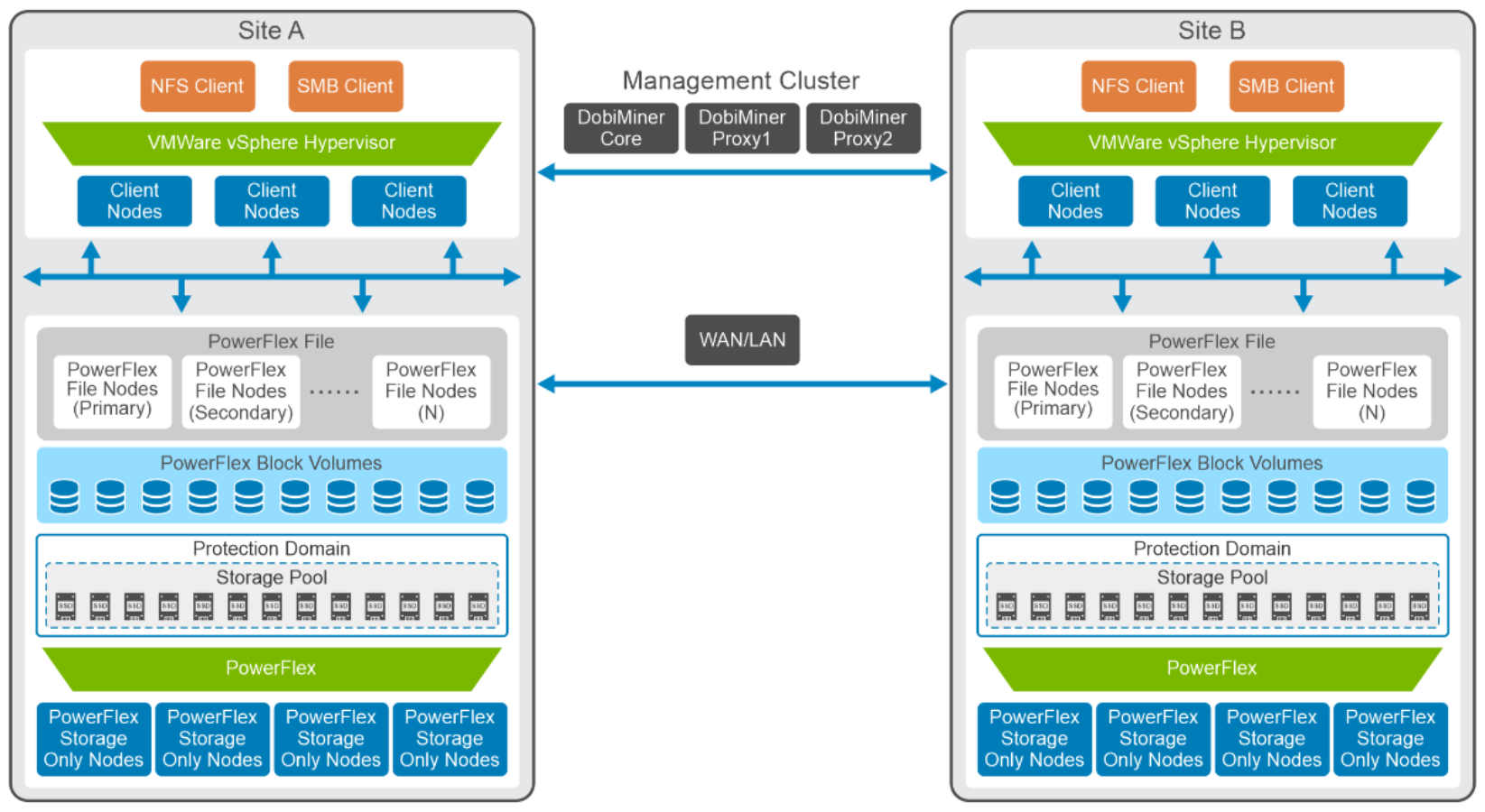
Figure 5. Logical design for PowerFlex file replication using StorageMAP
The client nodes are used to deploy Windows and Linux clients to mount the SMB and NFS file shares respectively. The DobiMiner core and DobiMiner proxies are installed and connected to both Site-A and Site-B File Servers.
On the storage side, PowerFlex Manager is used to deploy a PowerFlex storage node on four bare metal servers. Similarly, PowerFlex Manager is used to deploy PowerFlex file cluster on two PowerFlex file nodes.
For more information about installation and configuration of PowerFlex, see Dell PowerFlex Install and Upgrade Guide.