
Metro-based NDM walkthrough guide (source running 5977 or 5978 code)
Metro-based NDM walkthrough guide (source running 5977 or 5978 code)
-
Using Unisphere for PowerMax
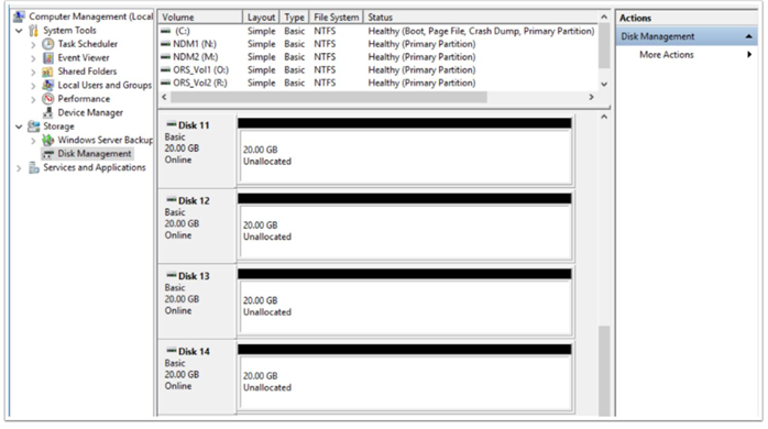
Looking at the devices in this migration from the host operating system disk management (in this case, Windows Server 2016), they show as Disk 11 through Disk 14. These were previously added as RDMs to the VMs using VMware vSphere.
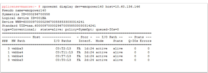
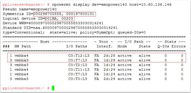
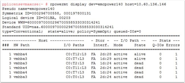
This is an example of the multipathing setup using device 1BA. It shows what the pathing looks like prior to the NDM Create operation and the host rescan. For each of the four volumes here there are four paths to the source array which are all alive and available for host use. At this point, there are no paths to the target array even though our zoning should be in place before the NDM create.
NDM environment setup
The Environment Setup operation configures the migration environment template required to setup the Metro groups used to migrate all applications from the source array to the target array. This template is used to define the RDF groups for each migration session. Within this definition are ports used, target ports and port count. The operation also confirms that both the source and target arrays can support the NDM operations. This includes ensuring that a usable replication pathway for data migration is available between source and target arrays. Should we need a second target array from the same source, a second environment is necessary.
To summarize, the Environment Setup runs once only for each array relationship. This Setup operation creates a template from which all other Metro-based NDM SRDF groups are modelled. Each individual NDM session requires its own RDF/Metro group to be created unlike Pass-through NDM which used a single RDF group for all sessions between the source and target.

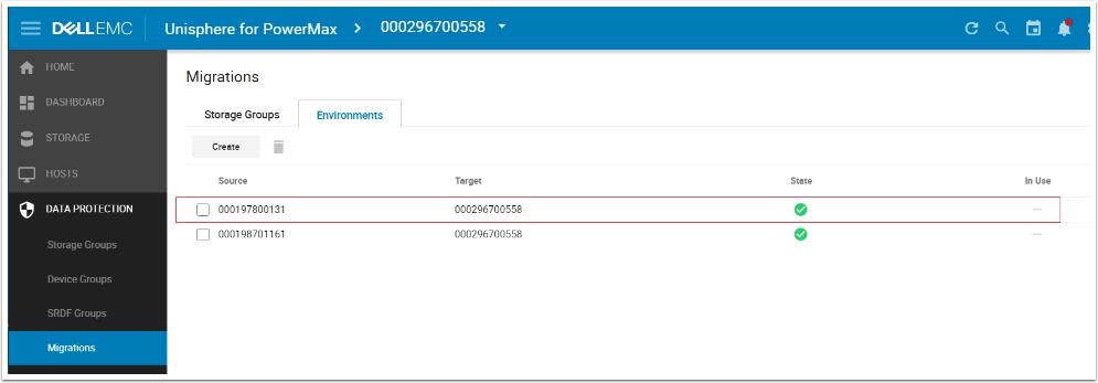
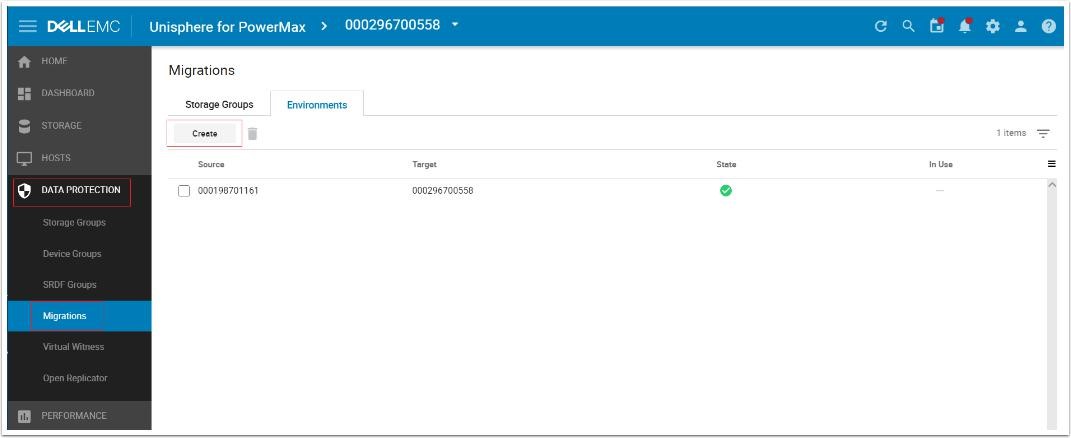
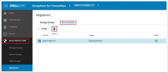
From the Data Protection menu select Migrations, Click the Environment tab to display any existing Environments already setup. The parameter In Use shows us whether the Environment is validated and usable. The In Use parameter also shows whether there is an active Migration using this environment.
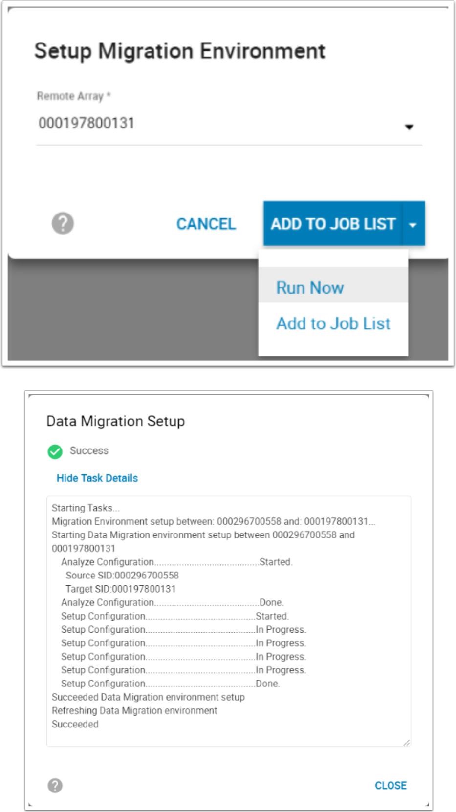
To create an environment click Create, the pop-up window below appears. This contains a drop-down list of all the arrays available for migration operations. Should your array not be present, verify the RDF zoning and confirm the intended target array is suitable and its code level is within the support matrix. Select the relevant array and choose Run Now.
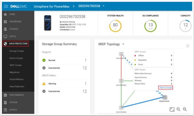
The new Topology view we can see the RDF group template that has been created. Go to the DataProtection dashboard and hover over the line between our source and target. This causes the SRDF Groups window to appear. Select View Groups to display the SRDF group window highlighted below.

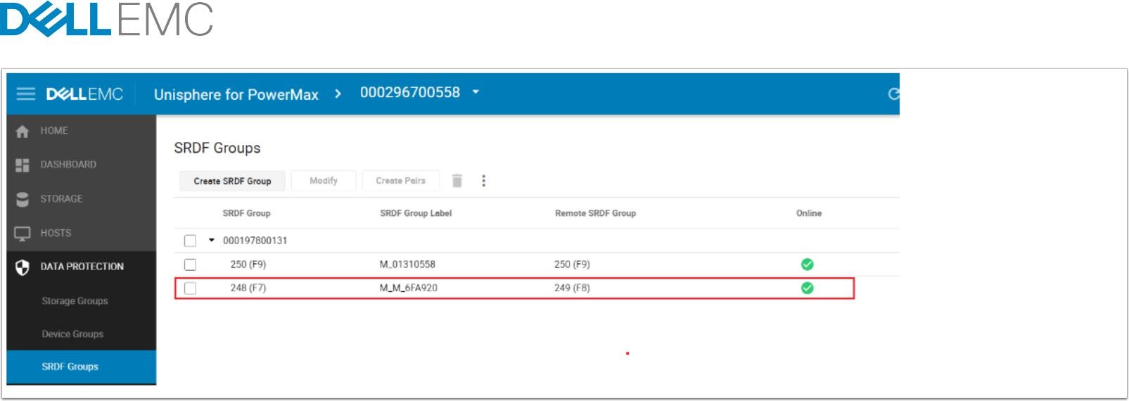
From an RDF standpoint you can examine the new RDF group created to handle NDM migrations for all SG sessions between 558 and 131.

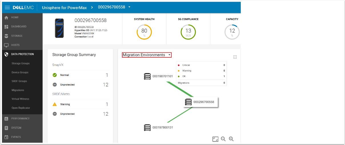
From the same Data Protection dashboard, the drop-down menu contains an option to monitor Migration Environments. A color-coded line indicates any problems. Hovering over the connection line displays the number of each connection status.
Now the Environment is in place so the NDM Create for the SG planned for migration can occur.
Create migration session
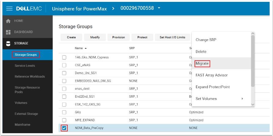
From the Storage tab click Storage Groups, from there locate the SG that is to be migrated. Select the check box and click the More Actions "3-Dot" icon to the right of Set Host I/O Limits. From the drop-down menu select Migrate.

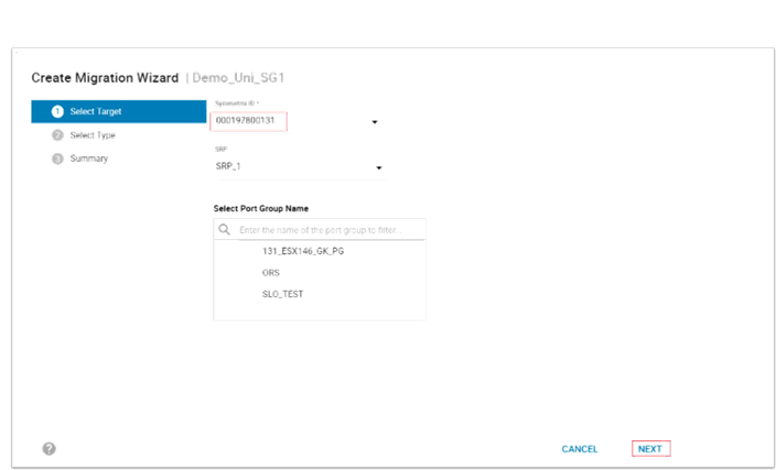
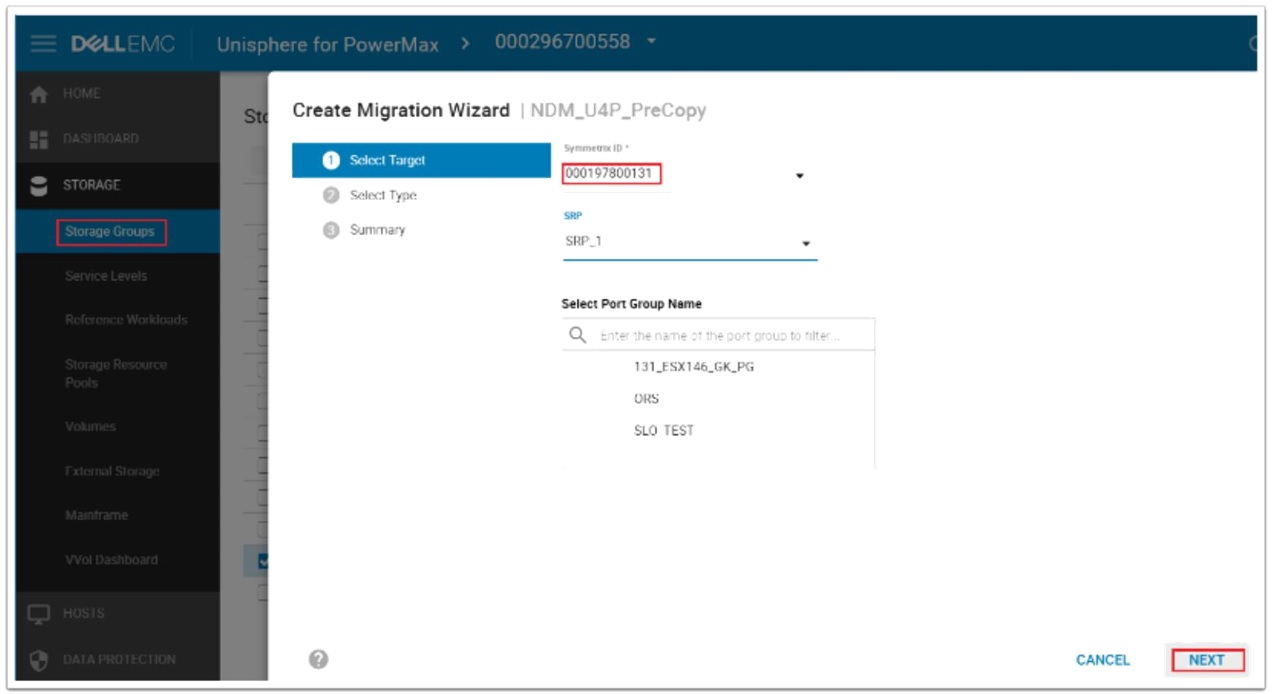
In the Create Migration Wizard, select the Target array (only arrays with valid environments setup appear on this drop-down menu). This example does not select a Port Group. (See the relevant masking enhancements section.) Click Next.
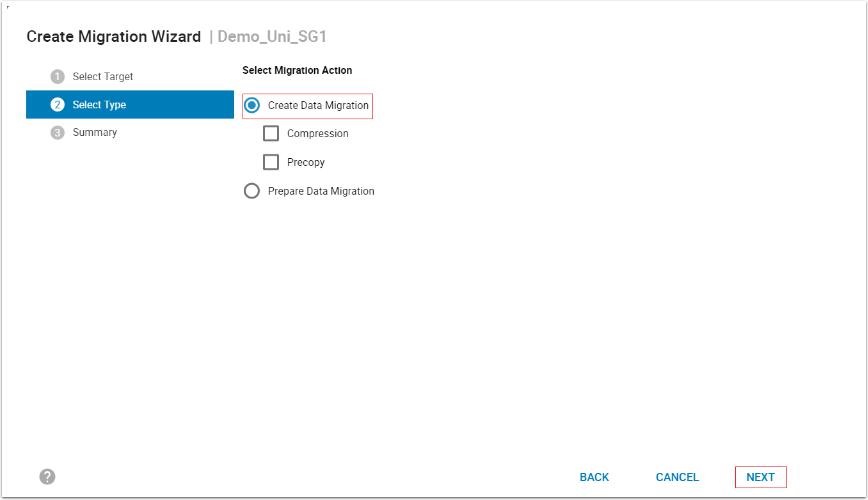
On the next screen click Create Data Migration. This provides the option of selecting Compression and precopy. The scenario that this part of the example covers does not use precopy, so that remains cleared.
(See precopy section) and select Next. The Prepare Data Migration selection requires Performance data to be collected on the host.
This runs a check for resources on the target array to ensure the addition of the new SG does not cause the target array to exceed any performance metrics on both FE and BE. It also produces a spread sheet to help plan the zoning required for the host from the target array.
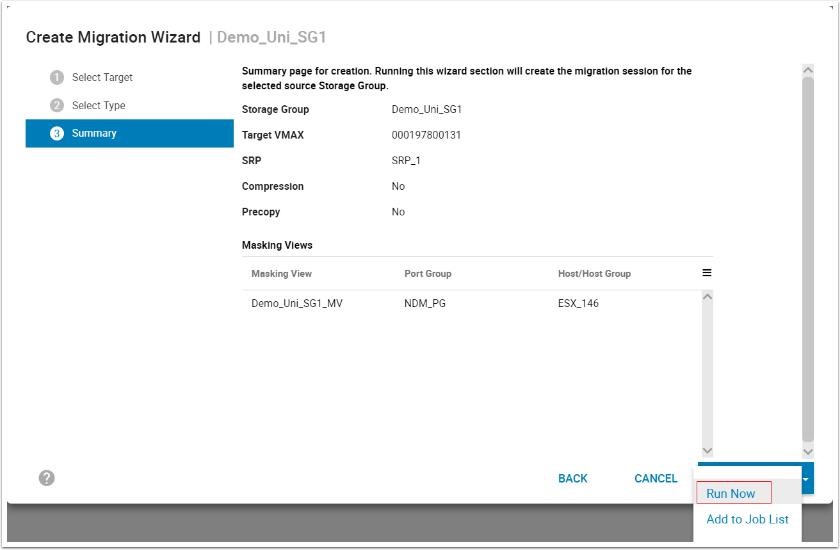
The final page of the Wizard summarizes the planned NDM session to be created. It breaks down the planned masking view elements and the NDM parameters. Select Run Now to continue.
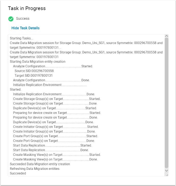
Creating the NDM session will also perform an Environment validate as part of the setup to ensure it will complete successfully. As outlined in the create command output, the Create:
- Creates a Storage Group on the Target array (name must not already exist in the target array) with the same name as the Source SG.
- Creates duplicate devices on the target array to match those on the Storage Group
- Creates an initiator group using Initiators with entries in the login history table
- Creates a Port group (if one does not already exist or has not been selected by the user, see the relevant masking enhancements section)
- Invalidates the tracks on the RDF mirror to prepare for the copy
- Starts the copy process.
- Creates a masking view to the host from the target array.
Examine the created migration session
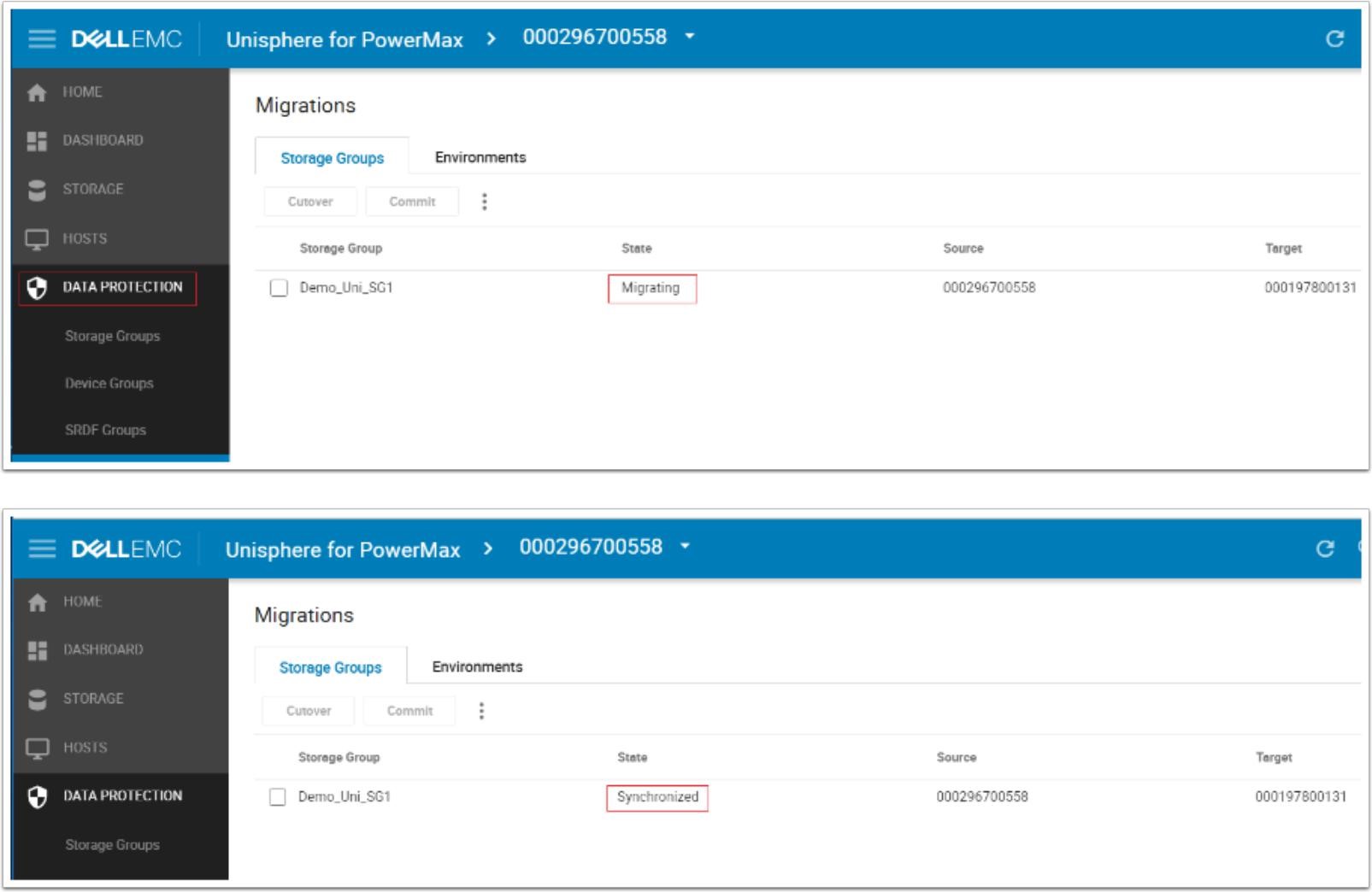
Selecting the Data Protection tab on the left task bar and selecting Migrations in the drop-down menu, the storage groups currently involved in an NDM session are highlighted along with the current State and details on the source and target arrays. Since data transfer begins immediately following a Create operation there is no need for the Pass-Through NDM Cutover operation. Once the data is synchronizing the systems administrator runs a rescan to allow the target paths to become active to the multipathing software. At this point, both source and target arrays are involved in an active/active relationship with all I/O serviced locally.
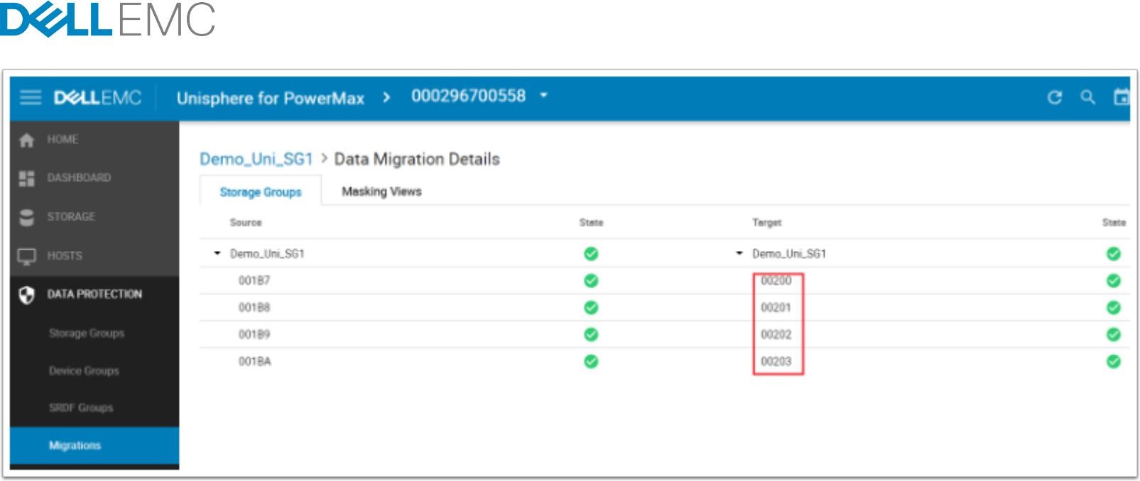
Double-clicking the NDM session will take you into the Migration Details view. In the screen above, we can see the individual devices involved in the session. Under the target tab we can see devices 200 through 203 have been created on the target side by the NDM create. The State also shows a live status of each of the devices involved. A device without a green tick should be investigated for potential problems before continuing.

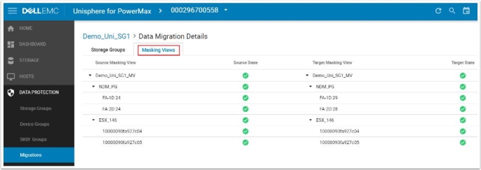
Selecting the Masking Views tab displays the pane outlining the masking and masking elements involved on both sides of the NDM session. This screen can be useful for troubleshooting any issues with the migration such as an unplanned or unauthorized manipulation of any of the NDM elements that hinder progress to the commit stage. In such cases the State does not contain a green tick, rather a red warning.

Examining the RDF environment from the Topology view shows the RDF group template that has been created. Go to the DataProtection dashboard and hover over the line between our source and target. This causes the SRDF Groups window to appear. Select View Groups to display the SRDF group window highlighted below.
The new SRDF group that has been created (248/249 on remote) as part of the Create command operation from the template (250). Group 248 is used for the duration of this migration.

View paths to new devices and SRDF pairs
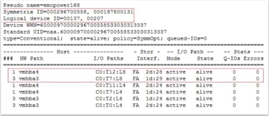
Viewing the multipathing software after the rescan shows the extra paths online to the target array (in this case two extra paths) The number of extra paths is dependent on the zoning setup. It also displays the source and target SIDs and the device numbers involved for these paths. The WWNs on the LUNs to appear as a single device with just extra paths. Prior to version 6.2 PowerPath was not aware of the NDM process so the dual SIDs and devices IDs were not visible.
Once the Create operation and the scan have both completed, the migration is in an active/active functional state with I/Os being distributed to both source and target paths. Bias is set on the Source side which differs from Pass-Through NDM where the source side was the R2 in a standard R1- R2 synchronous relationship. The state in Unisphere is displayed as ActiveBias as we do not have a witness attached to this metro relationship. However, we are truly active/active from an array perspective.

Examine IDs of source and target
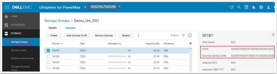
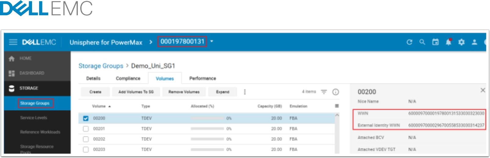
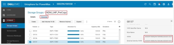
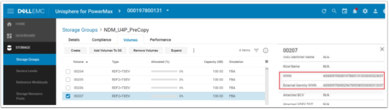
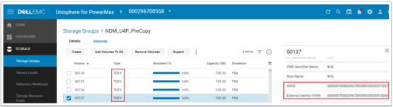
Examining the devices WWNs post Create the source device has a WWN and External (host visible) WWN with the same value. However, the targets WWN and External WWNs differ. The target External WWN has inherited the WWN of the source in order to appear logically as the same device to the host.

Cancel a migration
To Cancel a migration, click the Data Protection tab and select Migrations from the drop-down menu. Select the active NDM session and click the More Actions (three Dots) menu and Cancel Migration.

Confirm the cancel operation of the SG with the correct source and target and click Run Now.
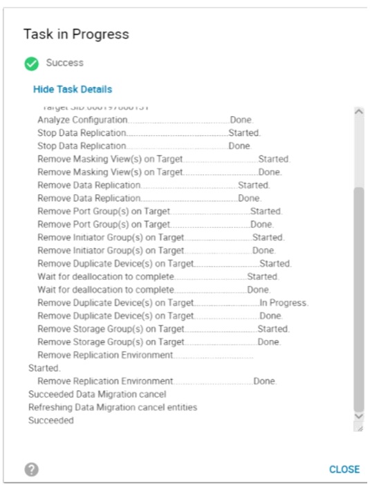
The cancel operation removes the storage provisioned on the target array and releases any allocations and resources allocated by the NDM create operation. It also places the source devices into the same state they were before the create operation was issued.
The cancel operation:
- Stops replication between the source and target arrays
- Removes the masking view on the target array
- Removes the RDF pairings
- Removes the port group on the target array (if not in use in another masking view)
- Removes the initiator group on the target array
- Deallocates volumes created on the target array
- Removes the devices created on the target array
Note: It is best practice to run a rescan on the host should be run at this point to remove any dead or invalid paths.
Commit a migration
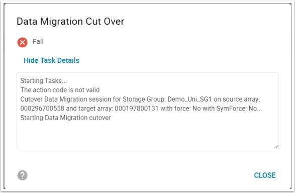
If an attempt is made to issue a cutover on a Metro NDM session, the above error will occur. This cutover command is only for Pass-through NDM (source array running 5876 code).
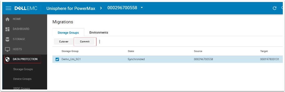
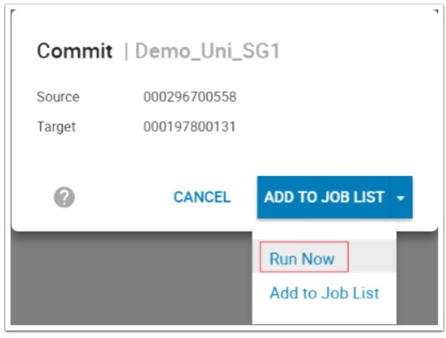
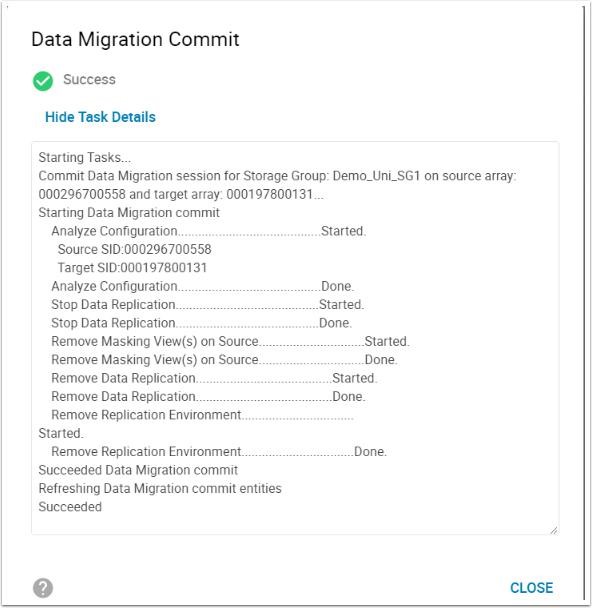
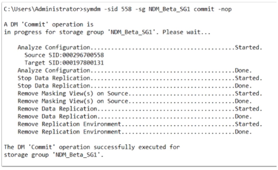
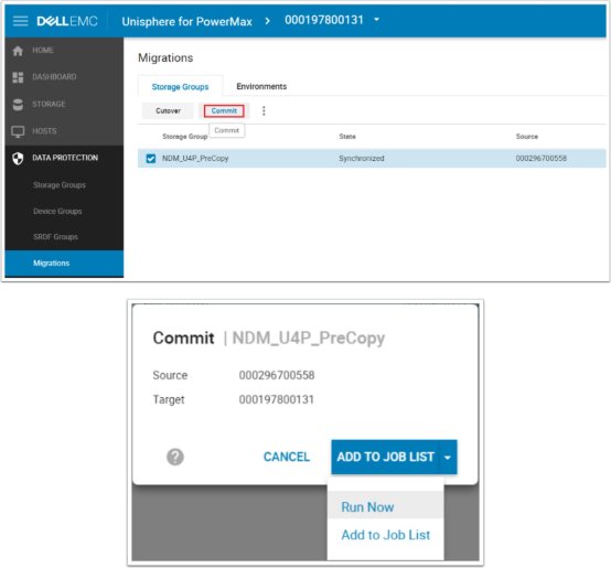
When the data commit operation is completed and the devices are synchronized, the migration can be committed. The Commit operation completes the migration by removing the migrated application resources from the source array and releases system resources used for the migration. Once the commit is completed the replication relationship between the source and target devices are removed, the masking view on the source removed and the source devices take the native (internal) WWN of the target LUN as its effective (external) WWN.
The target has an external WWN of the source and the source having an external WWN of the target. Both devices retain their native (internal) WWNs but these are not presented to the host.
Examine paths and device post commit
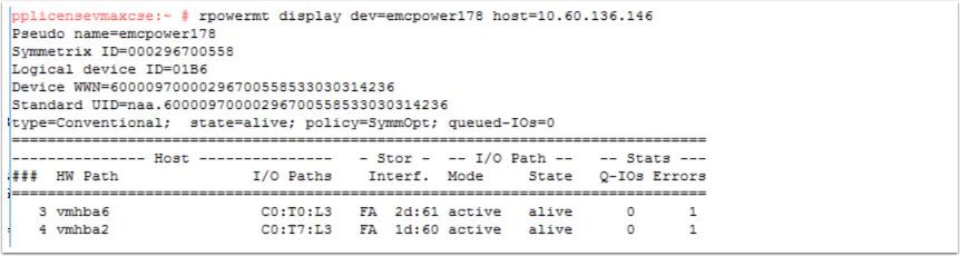
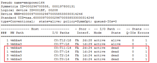
Post Commit and with the removal of the source masking view and before the host rescan the original Source paths are in a dead state. (This varies depending on your MP software) The two target paths are still active.
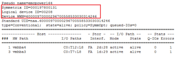
Once the host Rescan has been completed, the dead paths are now removed and the SID that of the target array. The WWN inherited from the source array is displayed as before to allow the distinction of NDM devices.

Viewing the source and target devices after the Commit operation clearly shows the WWN manipulation that has occurred. The Source device now has the target’s native WWN as its effective WWN and the target device has retained the source native WWN as its effective WWN.
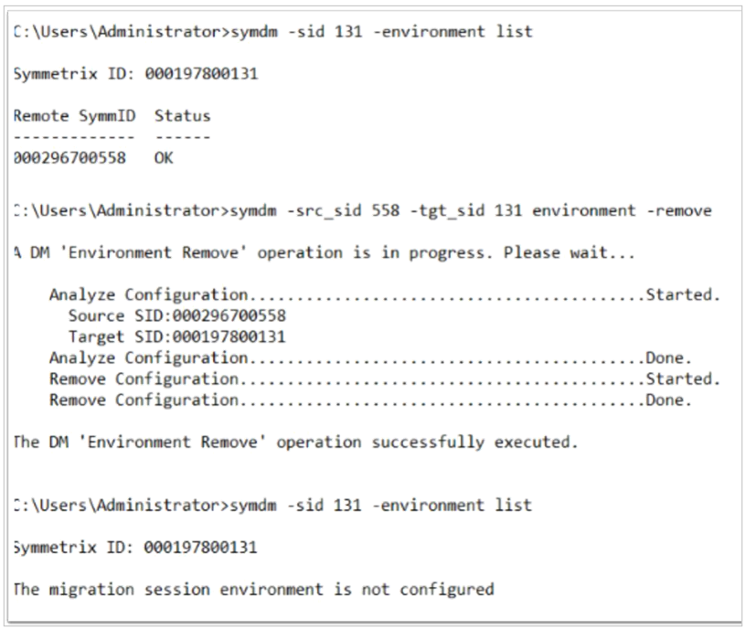
Remove NDM environment
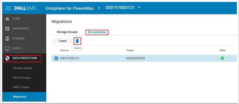
When all migrations are complete between a specific source and target, the environment can be removed. Click the Data Protection tab and click Migrations. On the Environments tab, select the Environment and click the trash icon. On the window that appears, click Run Now and the Environment is removed. This removes the RDF group setup and releases those resources.
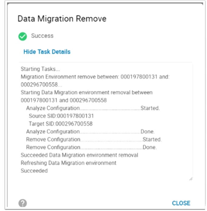
Note: At this point, the data migration is completed and the migration environment is removed for the specific source and target.
Using Metro NDM using Solutions Enabler 9.x
View devices from the host
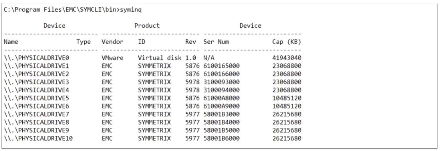
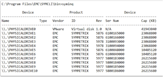
This screenshot shows the New Devices view using the Syminq command, and the devices added to the host as PhysicalDrive7 through PhysicalDrive10.
PowerPath view of one of the new devices
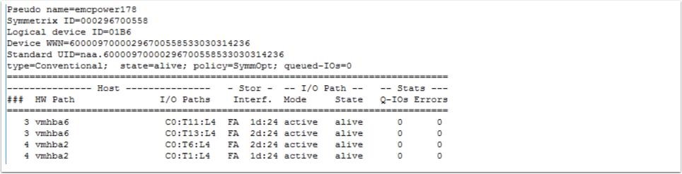
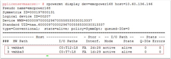
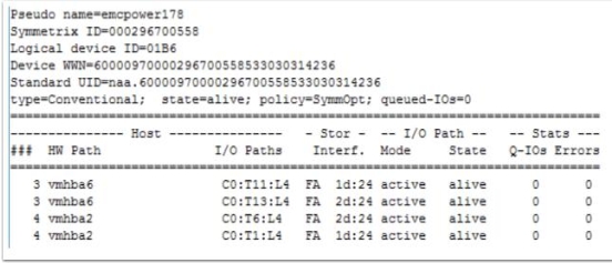
PowerPath shows what the pathing looks like prior to the NDM Create (in this case dev 1B6) and the host rescan. For each of the four volumes, there are four paths to the source array. All are alive therefore available for host use. We do not yet have any paths to the target array.
Environment setup
The Environment Setup configures the migration environment template required to create SRDF/Metro groups for the migration of any application from the source array to the target array. It confirms that both the source and target arrays can support NDM. This includes that a usable replication pathway for data migration is available between the source and target. This needs to be issued once only as the environment is to be used for all migrations between these arrays.
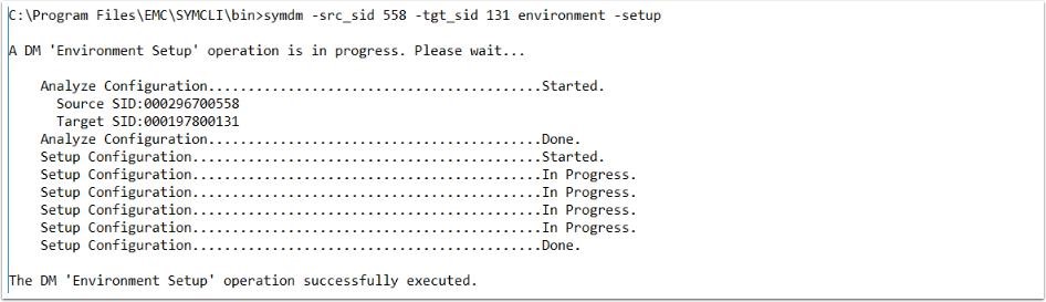
symdm –src_sid <SN of Source> -tgt_sid <SN of Target> environment -setup
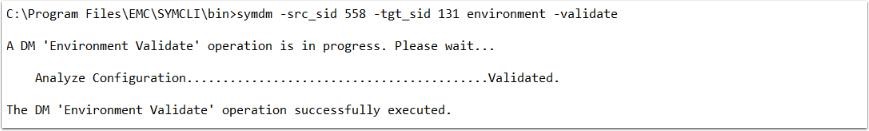
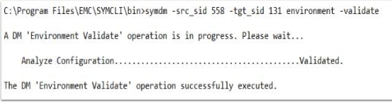
Validate environment
To validate the recently created environment or an existing environment to an alternative array use the - validate option to the symdm environment command.
symdm –src_sid <SN of Source> -tgt_sid <SN of Target> environment -validate
Validating and creating an NDM session
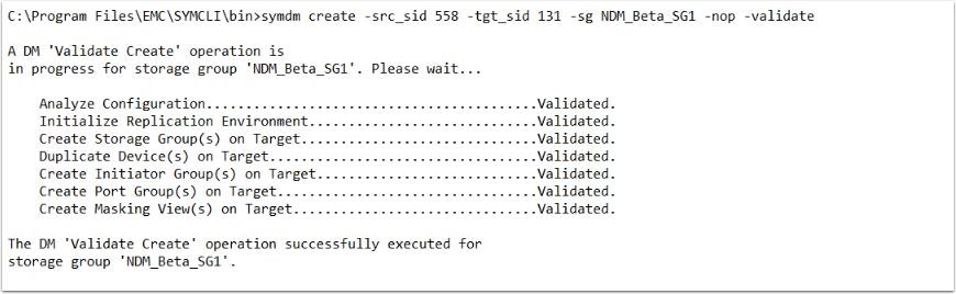
Solutions Enabler examines a specific application’s storage on the source array and automatically provisions equivalent storage on the target array. The target devices are assigned the identity of the source devices. Prior to running the create operation, it is always worth running the -validate to ensure the planned migration can succeed. This allows any potential issues to be addressed leading into the migration window.
symdm –src_sid <SN of Source> -tgt_sid <SN of Target> -sg <SG to be Migrated> -validate
If any of the above fails, it is worth taking a look at the SYMAPI log file, which, more often than not, points you toward an easily correctable issue within a masking view or zoning config. In the following example, one of the initiators in the source IG in an IG on the target array.
08/31/2017 12:41:28.688 EMC:SYMDM validateIGEntryInMul The initiator wwn 10000090fa927c04 is already in use in Initiator Group 131_GKs_IG for array 000197800131
08/31/2017 12:41:28.688 Create Initiator Group(s) on Target............................Failed.
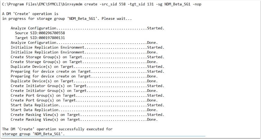
Creating the NDM session also does a -validate of the environment to ensure the subsequent steps complete successfully. The Create operation:
- Creates a Storage Group on the Target array (name must not already exist in the target array) with the same name as the Source
- Creates duplicate devices on the target array to match those on the Storage Group
- Creates an initiator group using Initiators with entries in the login history table
- Creates a Port group (if one does not already exist or has not been selected by the user, see the relevant masking enhancements section)
- Invalidates the tracks on the RDF mirror to prepare for the copy
- Starts the copy process.
- Creates a masking view to the host from the target array.
symdm –src_sid<SN of source> -tgt_sid<SN of Source> -sg<Sg to Migrate> -tgt_SRP <SRP on Target>
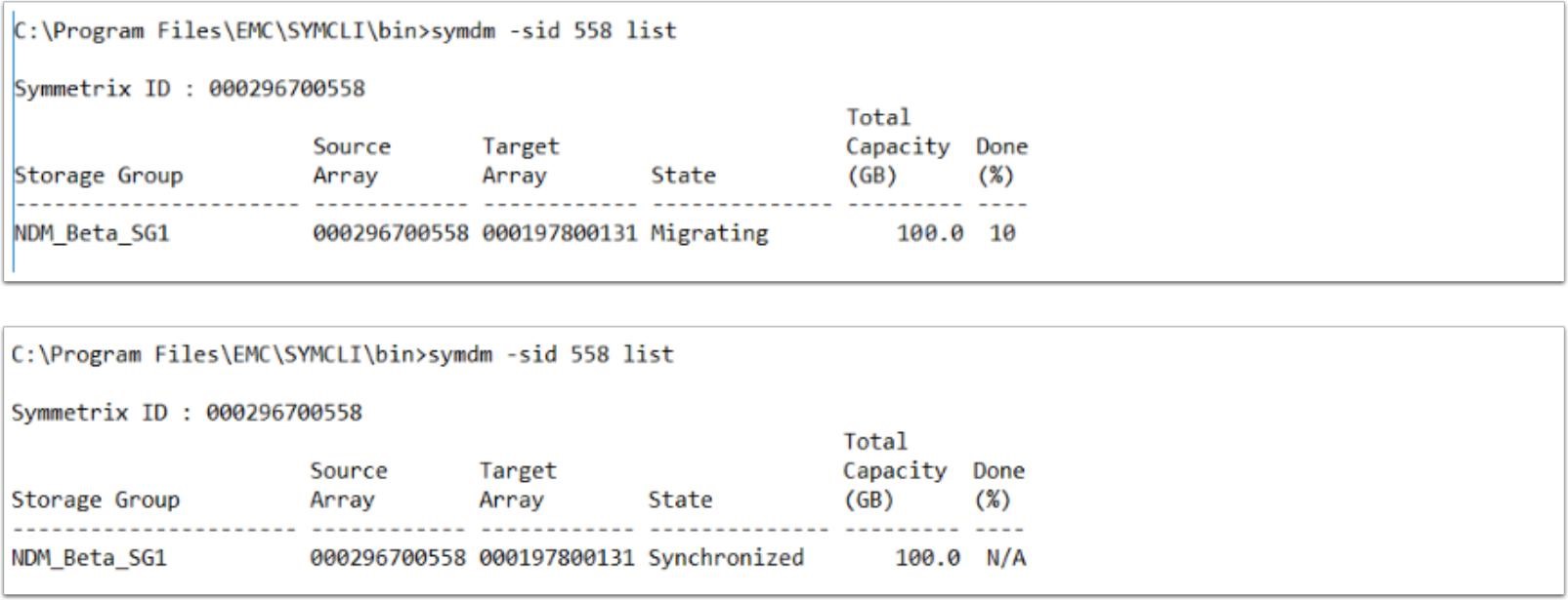
Viewing migration sessions
As outlined in the introduction NDM from 5977 to 5978 removes the Cutover operation and need for Pass-through mode. Once the Create operation has completed, data transfer begins immediately. As this example shows, the session entered a migration state and began copying data to the target as soon as the Create operation completed.
Once the migration is complete the system administrator runs a Host Rescan. This allows the multipathing software to discover extra paths to the host. Since Metro-based NDM uses SRDF/Metro as its transmission medium I/O operations passed through the target array. All writes are saved locally and replication to the remote array is handled by SRDF/Metro.

The example shows two additional paths to the device. These are the new paths to the target array. The number varies based on the number of paths zoned.
If target side Disaster Recovery (DR) is required, it is possible to start the process while the migration is ongoing. This can be setup using the standard symrdf commands:
symrdf addgrp -sid 131 -rdfg xx -dir xx -label xxxx -remote_dir xx -remote_sid xxx - remove_rdfg xx
symrdf createpair -establish
Examining the NDM session in more detail
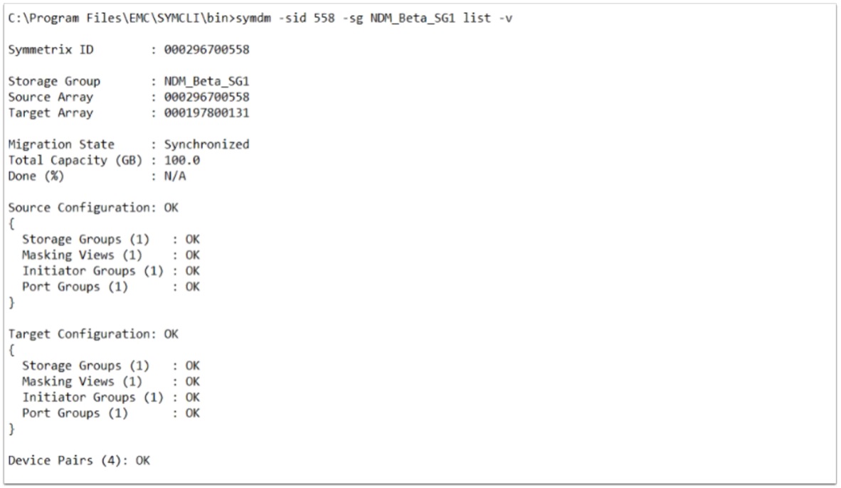
There are a number of ways of viewing the Session in more detail using the list -v commands. This section shows a summary of the selected session and verifies all entities are valid prior to attempting a Commit operation. Adding a -detail to this command option displays a complete breakdown of all the individual masking elements.
symdm –sid <SN of Source> -sg< SG to be Migrated> list -v
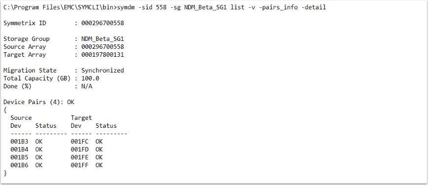
To view the LUN pairings, try using the -pairs_info parameter.
symdm –sid<SN of SRC or TGT> -sg <SG to be Migrated> list –v –pairs_info -detail
Host view of the devices
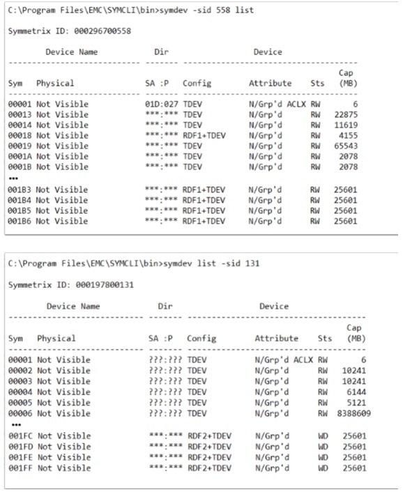
A symdev from the host shows the Label of RDF1 and RDF2 against the source arrays, in contrast to pass-through NDM the source device would have been given an R2 Mirror to cater for Pass-through mode. This does not apply for Metro NDM.
symdev –sid <SRC or TGT SN> list
Source and target post-create
The native and effective (internal and external) devices IDs (WWNs) are the same on the source device 1B3.
Symdev –sid <SRC or TGT> show <SRC or TGT device>

The native and effective (internal and external) devices IDs (WWNs) differ on the Target Array. The target device has inherited the WWN of the source and presented it as its effective or external WWN.
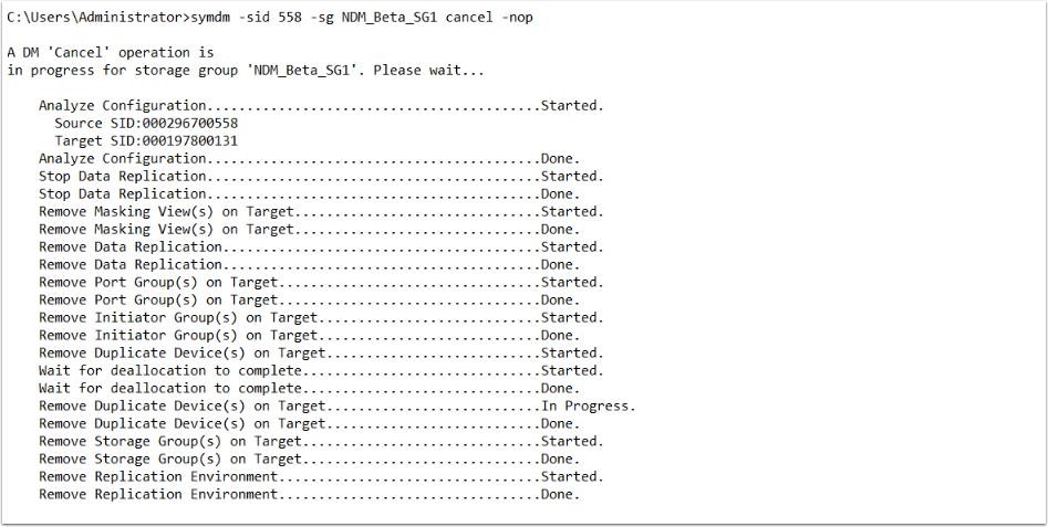
Canceling a migration in progress
At any point up to the Commit, a migration can be canceled. This removes the storage provisioned on the target array and releases any allocations and resources allocated by the NDM create operation. It also returns the source devices to the state they were before the Create operation was issued.
The cancel operation carries out the following:
- Stops replication between the source and target arrays
- Removes the masking view on the target array
- Removes the RDF pairings
- Removes the port group on the target array (if not in use in another masking view)
- Removes the initiator group on the target array
- Deallocates volumes created on the target array
- Removes the devices created on the target array
Since there is no Cutover operation and therefore no pass-through state there is no need to use the - revert parameter as used in Pass-Through NDM.

Committing a migration
When the data copy is completed, and the devices are synchronized the migration can be committed. The Commit operation completes the migration by removing the migrated application resources from the source array and releases system resources used for the migration. Once the Commit operation is completed, the replication relationship between the source and target devices is removed, the masking view on the source is removed, and the source devices take the native (internal) WWN of the target LUN as its effective (external) WWN.
This leaves the target having an external WWN of the source and the source having an external WWN of the target. Both devices retain their native (internal) WWNs but these are not presented to the host.
symdev –sid <SRC or TGT SN> -sg <SG to be Migrated> commit
Examining a device after the commit operation
With the removal of the masking view to the source storage array the systems administrator runs a host rescan. This removes any dead paths.
Viewing the source and target devices after the Commit operation shows the WWN manipulation that has occurred. The source device now has the targets native WWN as its effective WWN and the Target device has retained the source native WWN as its effective WWN. In addition, the RDF mirror has been removed from the device.
Removing the migration environment
Removing the environment removes the template used to create the SRDF/Metro groups for individual SG migrations. Once this template is removed another Environment Setup operation is necessary, which creates a new template, before being able to create migrations between the source and target arrays.
Using Unisphere for PowerMax with precopy
Looking at the devices in this migration from the host operating system disk management (in this case, Windows Server 2016), they show as Disk 16 through Disk 19. These were previously added as RDMs to the VMs using VMware vSphere.

An example of the multipathing setup using device 137. It shows what the pathing looks like prior to the create and the host rescan. For each of the four volumes here there are four paths to the source array which are all alive and available for host use. At this point, there are no paths to the target array even though our zoning should be in place before the NDM create.

NDM environment setup
The Environment Setup operation configures the migration environment template required to setup the Metro groups used to migrate all applications from the source array to the target array. This template is used to define the RDF groups for each migration session. Within this definition are ports used, target ports and port count. The operation also confirms that both the source and target arrays can support the NDM operations. This includes ensuring that a usable replication pathway for data migration is available between source and target arrays. Should we need a second target array from the same source, a second environment is necessary.
To summarize the Environment Setup runs once only for each array relationship. This Setup operation creates a template from which all other Metro-based NDM SRDF groups are modeled. Each individual NDM session requires its own RDF/Metro group to be created unlike Pass-through NDM which used a single RDF group for all sessions between the source and target.
From the Data Protection menu select Migrations, Click the Environment tab to display any existing Environments already setup. The parameter In Use shows us whether the Environment is validated and usable. The In Use parameter also shows whether there is an active Migration using this environment.
To create an environment, click Create, and the window below appears. This contains a drop-down list of all the arrays available for migration operations. Should your array not be present, verify the RDF zoning and confirm the intended target array is suitable and its code level is within the support matrix. Select the relevant array and choose Run Now.

The new Topology view we can see the RDF group template that has been created. Go to the DataProtection dashboard and hover over the line between our source and target. This causes the SRDF Groups window to appear. Select View Groups to display the SRDF group window highlighted below.
The new SRDF group that has been created (248/249 on remote) as part of the Create command operation from the template (250). Group 248 is used for the duration of this migration.
From an RDF standpoint you can examine the new RDF group created to handle NDM migrations for all SG session between 558 and 131.

From the same Data Protection dashboard, the drop-down menu contains an option to monitor Migration Environments. A color-coded line indicates any problems. Hovering over the connection line displays the number of each connection status.

Now the environment is in place so the NDM Create for the SG planned for migration can occur.
Create migration session with precopy
From the Storage tab click Storage Groups, from there locate the SG that is to be migrated. Select the check box and click the More Actions "3-Dot" icon to the right of Set Host I/O Limits. From the drop-down menu select Migrate.
In the Create Migration Wizard, select the Target array (only arrays with valid environments setup appear on this drop-down menu). This example does not select a Port Group. (See the relevant masking enhancements section.) Click Next
On the next screen click Create Data Migration. This provides the option of selecting Compression and precopy. Check Precopy and select next. The Prepare Data Migration selection requires Performance data to be collected on the host. This runs a check for resources on the target array to ensure the addition of the new SG does not cause the target array to exceed any performance metrics on both FE and BE. It also produces a spread sheet to help plan the zoning required for the host from the target array.
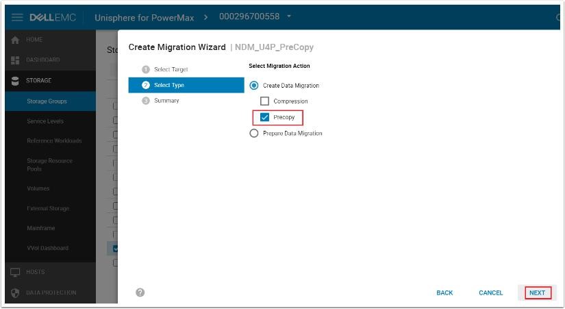
The final page of the Wizard summarizes the planned NDM session to be created. It breaks down the planned masking view elements and the NDM parameters. Select Run Now to continue.

Creating the NDM session with the precopy option will also perform an environment validate as part of the setup to ensure it will complete successfully. As outlined in the create command output, the Create command completes the following:
- Creates a storage group on the target array (name must not already exist in the target array) with the same name as the Source
- Creates duplicate devices on the target array to match those on the storage group
- Creates an initiator group using Initiators with entries in the login history table
- Creates a port group (if one does not already exist or has not been selected but the user (see the relevant masking enhancements section)
- Starts the copy process in SRDF/Adaptive Copy mode
Examine the created migration session
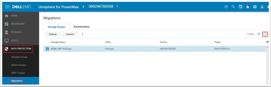
Selecting the Data Protection tab on the left task bar and selecting Migrations in the drop-down menu, the storage groups currently involved in an NDM session are highlighted along with the current State and details on the source and target arrays. Since data transfer begins immediately following a Create operation, there is no need for the Pass-
Through NDM Cutover operation. Once the data is synchronizing the systems administrator runs a rescan to allow the target paths to become active to the multipathing software. At this point, both source and target arrays are involved in an active/active relationship with all I/O serviced locally.
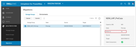
From the expanded menu in this example, the precopy is now 16% completed.
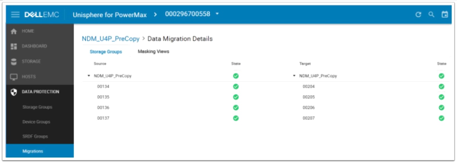
Double-clicking the NDM session will take you into the Migration Details view. In the screen above, we can see the individual devices involved in the session. Under the target tab, we can see devices 204 through 207 have been created on the target side by the NDM create. The State also shows a live status of each of the devices involved. A device without a green tick should be investigated for potential problems before continuing.
Selecting the Masking Views tab displays the pane outlining the masking and masking elements involved on both sides of the NDM session. This screen can be useful for troubleshooting any issues with the migration such as an unplanned or unauthorized manipulation of any of the NDM elements that hinder progress to the commit stage. In such cases the State does not contain a green tick, rather a red warning.
Examining the RDF environment from the Topology view shows the RDF group template that has been created. Go to the DataProtection dashboard and hover over the line between our source and target. This causes the SRDF Groups window to appear. Select View Groups to display the SRDF group window highlighted below.
Making the target array ready to the host
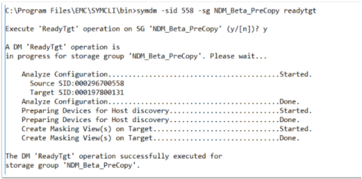
Once an adequate amount of data has been copied to the target array to negate the potential impact on the application host the target array can be made Ready to the Host.
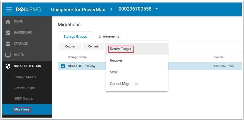
From the active Migrations tab click the more actions icon (three dots) to the right of the Commit button. In the drop-down menu, select Ready Target. Confirm the arrays and SG are the correct combination for this migration (if multiple concurrent NDM sessions are in place) and click Run Now.

When the ready target operation begins the RDF relationship changes to Metro from adaptive copy and the masking view is created. Running a host rescan the extra paths will become available for host I/O use:
- RDF group state moved from adaptive copy mode to Metro active
- Target Devices are moved into a Read/Write mode
- Masking view is created on the target array
- SRDF state between source and target switches to active/active
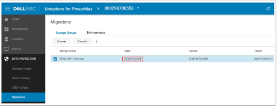
Once the ready target has been issued, we will move from a precopy state to a migrating state and eventually to a synchronized state.
At this point, the storage administrator will run a host rescan o allow the multipathing software to recognize the new paths created by issuing the Ready Target and the subsequent masking view creation on the target array. As the following figure shows, the extra paths to the target array as well as the dual device IDs sharing a single effective (external) WWN. By sharing a WWN the multipathing software sees the new devices as just extra paths to the original devices.
Selecting Storage Groups from the Data Protection tab and SRDF from the window to display the SRDF relationship. In this case, we are in ActiveBias as there is no witness between the arrays. From a system standpoint, we are now processing I/Os in a Metro active/active mode with our target array being read/write to the host also.

Examining the WWNs of source and target
Viewing the WWN of the source device after the Create operation shows that its internal and external (that is, host visible) WWN are identical. However, in contrast, the internal WWN and external WWNs of the target device are different. Its external WWN has inherited the WWN of the source device, which means that both devices appear as a single device to the host. In effect, the multipathing software sees additional paths to the same LUN.
Committing a migration
When the data copy is completed and the devices are synchronized, the migration can be committed. The Commit operation completes the migration by removing the migrated application resources from the source array and releases system resources used for the migration. Once the commit is completed the replication relationship between the source and target devices are removed, the masking view on the source is removed and the source devices take the native (internal) WWN of the target LUN as its effective (external) WWN.
The target device has the external WWN of the source and the source device has the external WWN of the target. Both devices retain their native (internal) WWNs but these are not presented to the host.

Device paths after the commit operation
The number of paths depends on the multipathing software in use and the zoning policy.
Carrying out a Rescan operation on the host removes the dead paths, retaining only the ones to the target devices. It also removes the SID of the original, target array, as shown in these images:
The following shows the pre-rescan status:

The post-rescan status is displayed as follows:
Viewing the details of the Source SG and devices demonstrate that the masking view to the host no longer exists, the RDF mirror is deleted from each of the devices and the Internal WWN from the target has been copied to the External WWN of the Source. This ensures the devices can remain on the same SAN without necessarily having to decommission the array entirely.

Similarly, the source device has lost its RDF mirror but retains its masking view to the host. The devices retain the Internal WWN of the Source in its External WWN identity it received at the Create stage.

Remove NDM environment
Once all migrations are completed for a specific source and target, the migration environment can be removed. Click the Data Protection tab and click Migrations. On the Environments tab, select the environment and click on trash icon to remove. On the confirmation screen, click Run Now. This deletes the RDF group setup and release its resources.
Using Solutions Enabler 9.x with precopy
The syminq command lists devices for migration. In this example, the devices are PhysicalDrive7 to PhysicalDrive10 consisting of VMAX devices 1B3 to 1B6.
PowerPath view of one of the new devices
PowerPath shows what the pathing configuration before the migration. (dev 1B6) For each of the four volumes there are four paths to the source array. All are alive and available for host use. There are no paths to the target array.
1.1.1.1 Environment setup
Environment Setup configures the migration environment template required to create SRDF/metro groups for the migration of any application from the source array to the target array. It confirms that both the source and target arrays can support NDM. This includes that a usable replication pathway for data migration is available between the source and target. This needs to be issued once as the environment is used for all migrations between these arrays going.
symdm –src_sid <SRC SN> -tgt_sid <TGT SN> environment -setup

Validate environment
To validate the recently created migration environment or an existing migration environment use the -validate command.
symdm –src_sid <SRC SN> -tgt_sid <TGT SN> environment -validate
Validating and creating an NDM session
Solutions Enabler examines a specific applications storage on the source array and automatically provisions equivalent storage on the target array. The target devices are assigned the identity of the source devices. Prior to running the Create command it is always worth running the –validate option to ensure the migration will be successful. This allows for the resolution of any issues before the migration takes place.
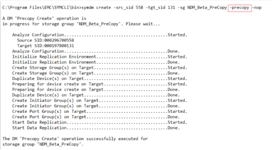
When issuing a Create with the -precopy parameter the Metro NDM session is created with the RDF relationship in SRDF/AdaptiveCopy disk mode. The data synchronization between R1 to R2 begins immediately. As with Metro-based NDM without precopy the source device is created with the R1 personality.
symdm –src_sid <SRC SN> -tgt_sid <TGT SN> -sg <SG to be Migrated> - tgt_srp <SRP on TGT> -precopy –validate
symdm –src_sid <SRC SN> -tgt_sid <TGT SN> -sg <SG to be Migrated> - tgt_srp <SRP on TGT> -precopy
If any stage in the validation fails, the contents of the SYMAPI log file often contain an indication of the problem. For example, a problem with an asking view or zoning conflict.
08/31/2017 12:41:28.688 EMC:SYMDM validateIGEntryInMul The initiator wwn 10000090fa927c04 is already in use in Initiator Group 131_GKs_IG for array 000197800131
08/31/2017 12:41:28.688 Create Initiator Group(s) on Target............................Failed.
Creating the NDM session with the precopy option will also perform an environment validate as part of the setup to ensure it will complete successfully. The create command performs the following:
- Creates a storage group on the target array that has the same name as the SG on the source array (the name cannot be in use on the target array already)
- Creates duplicate devices on the target array to match those on the storage group
- Creates an initiator group using Initiators with entries in the login history table
- Creates a port group (if one does not already exist or has not been selected but the user, see the relevant masking enhancements section)
- Starts the copy process in SRDF/adaptive copy mode
Viewing precopy status
While the precopy is ongoing the following commands are used to monitor its progress. It should be noted since this is an R1 - R2 RDF copy all of the usual RDF query commands are valid.
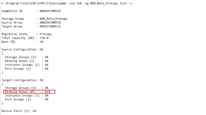
symdm –sid <SRC or TGT SN> list

Issuing the list command with the -v option the migration session displays a validation of the individual elements involved in the NDM session. Note the lack of masking view on the target side.
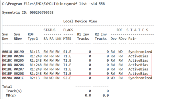
The symrdf list command shows the created pairs and the progress in terms of tracks to be copied to the R2 side. It shows the Mode (D) highlight the SRDF mode is Adaptive Copy displays the MB to track equivalent.
symrdf list –sid <SRC or TGT SN>

The symstat command shows the rate at which the precopy data is copying to the target side. This can be used to estimate the time to completion for scheduling purposes. This rate will vary depending on a number of factors including RAs involved, array level of activity and distance to target. Note the RDFG will not always be 248.
symstat –rdfg<RDFG of Migration> –type RDF –i –sid <SRC SN>

During the NDM environment setup process, the first choice will be RDFG 250, descending from this number until a free group is found. In the example shown multiple NDM environments setup from array 558 so RDFG 248 was free for 558 - 131. The RDFG number does not necessarily have to be the same on both source and target.

From an SRDF pair standpoint as shown in the example, we are fully synchronized to the target device.
It should be noted that it is not necessary to let the precopy to fully Synchronize before moving onto the next step and issuing the ReadyTarget command. Depending on the rate at which data is copying across and the amount of data to be copied it can be issued when the user feels comfortable I/O processing can be shared between the source and target array in an active/active configuration.
Make the target array ready to the host
Once the ReadyTarget command is issued and the systems administrator runs a rescan on the host, the migration will transition to a migrating state. If the ReadyTarget command was completed before the data has fully pre-copied the migration will enter a Migrating state until fully synchronized and then transition to a Synchronized state.
If the data has been fully pre-copied, the migration will briefly enter a migrating state to confirm data synchronization and then to a Synchronized state.
At this point, we are active/active to the host from both source and target arrays.
Issuing the ReadyTarget command performs the following:
- Moves RDF group state from adaptive copy mode to active/active
- Target devices are moved into a read/write mode
- Masking view is created on the target array using the masking elements created during the create command
symdm –sid <SRC or TGT SN> -sg <SG to be Migrated> readytgt
Following the ReadyTarget command and the host rescan the state changes to Synchronized.
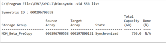
The symrdf list command now lists the pair state as ActiveBias signifying we are in Metro mode. And our target is read/write accessible to the host. The pairs source and target are active/active, but Solutions Enabler displays ActiveBias as there is not a witness present.
Canceling a migration
A migration can be canceled at any point up until the commit operation occurs. Cancellation removes the storage provisioned on the target array and releases any allocations and resources allocated by the NDM create –precopy operation. It also places the source deices into the state they were before the migration began.
The cancel operation performs the following:
- Stops replication between the source and target arrays
- Removes the masking view on the target array
- Removes the RDF pairings
- Removes the port group on the target array (if added as part of the create command)
- Removes the initiator group on the target array (if not in use)
- Deallocates volumes created on the target array
- Removes the devices created on the target array.
Since there is no cutover step, and therefore no pass-through state, there is no need for the use of a -revert parameter as used in legacy NDM.
symdm –sid <SRC or TGT SN> -sg <SG to be Migrated> cancel

It is best practice for the storage administrator to run a rescan on the host to clear up any dead or invalid paths left over after the migration has been canceled.
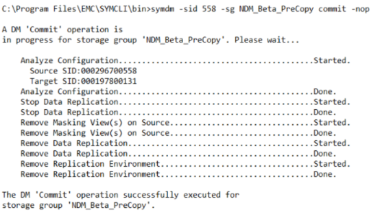
Committing a migration
When the data copy is completed and the devices are synchronized, the migration can be committed. The Commit operation completes the migration by removing the migrated application resources from the source array and releases system resources used for the migration. Once the commit is completed the replication relationship between the source and target devices are removed, the masking view on the source is removed and the source devices take the native (internal) WWN of the target LUN as its effective (external) WWN.
The target device has the external WWN of the source and the source device has the external WWN of the target. Both devices retain their native (internal) WWNs but these are not presented to the host.
symdm –sid <SRC or TGT SN> -sg <SG to be Migrated> commit
Device paths after the commit operation
The number of paths depends on the multipathing software in use and the zoning policy.
Carrying out a Rescan operation on the host removes the dead paths, retaining only the ones to the target devices. It also removes the SID of the original, target array, as shown in these images:
Following the Commit operation but before the storage administrator runs a rescan PowerPath still shows signs of the old NDM Session in the example above. The paths are dead but still present even though the masking view has been removed from the source array during the Commit command. The Logical Device still shows the old source device number despite the RDF pairs having been broken down and the application running solely on the target array. This is why we always recommend rescanning post create, post Cancel and Commit operations.
Once the storage administrator has run a host rescan the old paths to the source array are removed as well as reference to the source array logical device and ID.
Removing the migration environment
Removing the environment removes the template used to create the SRDF/Metro groups for individual SG migrations. Once this template is removed another Environment Setup operation is necessary, which creates a new template, before being able to create migrations between the source and target arrays.
symdm –sid <SRC or TGT SN> -environment remove
